ALE USA OAW-AP122X OmniAccess Stellar AP1220 series User Manual
ALE USA Inc. OmniAccess Stellar AP1220 series
UserManual.wiki
>
ALE USA
>
OAW-AP122X User Manual
>
User manual
Contents
1.
User manual
2.
User Manual (statement)
3.
User Manual
4.
User Manual (Statement)
User manual
Navigation menu
Upload a User Manual
Namespaces
Wiki Guide
HTML
PDF
Info
Views
User Manual
Discussion / Help
Navigation
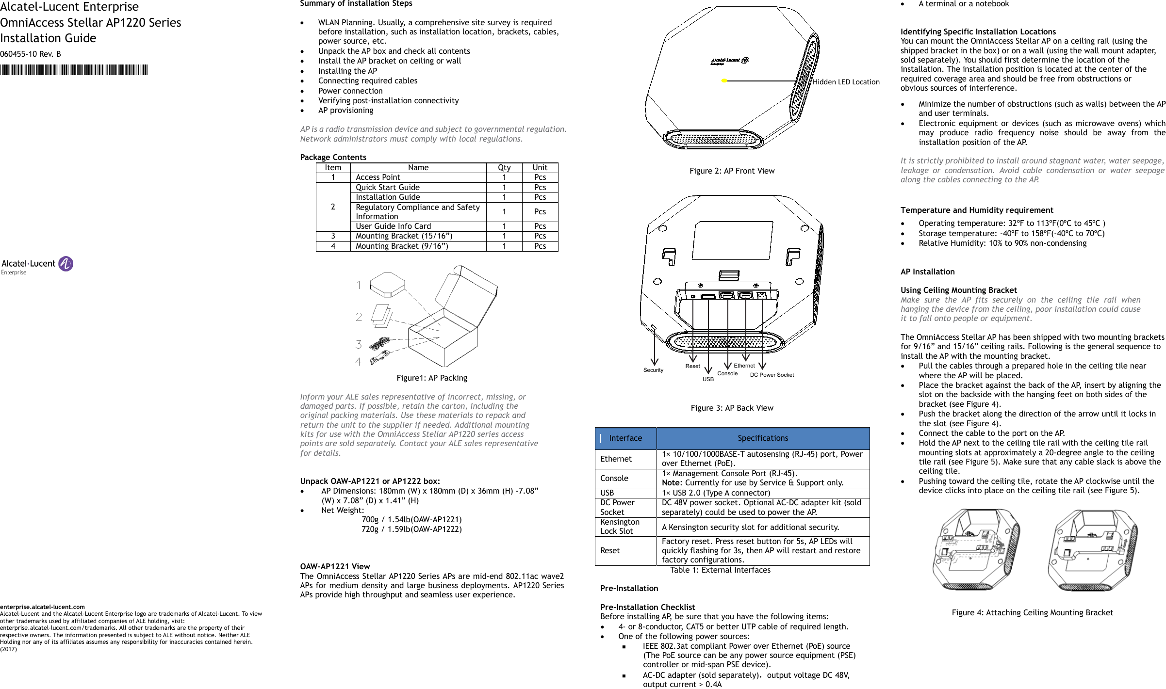
![Figure 5: Mounting AP Connect Ethernet Use the Ethernet port to connect the AP with a twisted pair Ethernet LAN segment. Use a 4- or 8-conductor, Category 5 UTP cable. The port is an RJ-45 female connector with the pinouts shown in Ta b l e 2. Connector Pin Signal Name GE FE PoE 1 2 3 4 5 6 7 8 1 RJ45_DA+ BI_DA+ RX+ PoE- 2 RJ45_DA– BI_DA- RX– PoE- 3 RJ45_DB+ BI_DB+ TX+ PoE+ 4 RJ45_DC+ BI_DC+ Spare PoE+ 5 RJ45_DC– BI_DC- BI_DA- Spare PoE+ 6 RJ45_DB– BI_DB- TX– PoE+ 7 RJ45_DD+ BI_DD+ Spare PoE- 8 RJ45_DD– BI_DD- Spare PoE- Tabl e 2: Ethernet Port Pinout Connect Power Sources Confirm that you have an IEEE 802.3at compliant Power over Ethernet (PoE) source on the Ethernet cable, if not, connect by using the ALE 48V AC-DC adapter kit (sold separately) to the DC Power Socket and AC power jack. If both PoE and DC power are available, the use of DC is preferred. OmniAccess Stellar AP supports the power adapter provided by ALE ONLY. Verifying Post-Installation Connectivity The LED on the AP can be used at this point to verify that the AP is receiving power and initializing successfully (see Table 3). Red Blue Green Time Line Status ON Power on ON Bootloader-OS loading System start up Flash System running Network abnormal (Interface down) Flash System running Network normal, without SSID created ON System running Network normal, singleband working, either 2.4Ghz or 5Ghz ON System running Network normal, dual bands working, 2.4Ghz and 5Ghz are both working Flash Flash System running Red and Blue LEDs alternate flashing in specific frequency; OS upgrading Flash Flash Flash System running 3 LEDs alternate flash- ing in specific frequency; Used for locating an AP Tabl e 3: OmniAccess Stellar AP LED Meaning Console Port The serial console port allows you to connect the AP to a serial terminal or a laptop for direct local management. This port is an RJ-45 female connector with the pinouts described in Table 4. Note: Currently for use by Service & Support only. Connector Pin Signal Name Function 1 2 3 4 5 6 7 8 3 TXD Transmit 4 GND Ground 5 GND Ground 6 RXD Receive Pins not listed are not connected. Table 4: Console Port Pinout Configuring the OmniAccess Stellar AP Refer to the Quick Start Guide and Configuration Guide for complete details. OAW-AP1222 View Figure 6 It is installed in the same way as OAW-AP1221. After the installation is complete, install the external antenna on OAW-AP1222 (see figure 7). Install the antenna as the figure 8: Figure7 Figure 8 The external antenna is sold separately. Contacting Alcatel-Lucent Enterprise Website Support Main Site http://enterprise.alcatel-lucent.com Support Site http://support.esd.alcatel-lucent.com Telephone Support North America 1-800-995-2696 Latin America 1-877-919-9526 Europe +800 00200100 (Toll Free) or +1(650)385-2193 Asia Pacific +65 6240 8484 Other Region 1-818-878-4507 [REMAINING SECTIONS INTENTIONALLY LEFT BLANK] Hidden LED Location](https://usermanual.wiki/ALE-USA/OAW-AP122X.User-manual/User-Guide-3550058-Page-2.png)