AOR USA ARDV1 Communications Receiver User Manual AOR AR 110 Steel picture facsimile unit
AOR USA Inc. Communications Receiver AOR AR 110 Steel picture facsimile unit
UserManual.wiki
>
AOR USA
>
ARDV1 User Manual
Users Manual
Navigation menu
Upload a User Manual
Namespaces
Wiki Guide
HTML
PDF
Info
Views
User Manual
Discussion / Help
Navigation
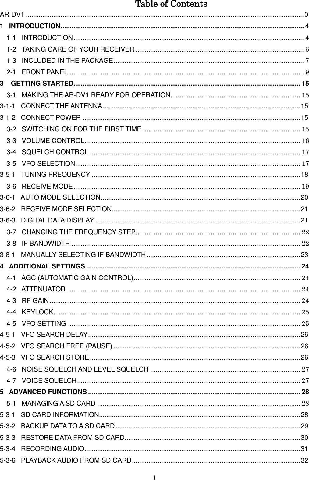
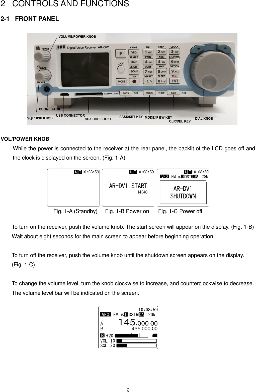
![10 SQL/DISP KNOB Rotate this knob to adjust the desired squelch level. Rotate clockwise until background noise goes off. The squelch level will be displayed on the screen according to the rotation of the squelch knob. When the knob is pressed, current squelch level will be displayed for 2 seconds. Push this knob for two seconds to view the squelch select menu, which will appear on the lower left of the display. The default setting is [AUTO]. Rotate the dial knob to select [AUTO], [LSQ], [NSQ]. (Note: LSQ: Level squelch, NSQ: Noise squelch) To confirm selection, press the knob. PHONE JACK Use headphone with a 3.5mm plug. When a headphone is connected, the internal speaker will be disabled. LCD 1 (F) Function switch 2 (R), (P) (R) Recording (P) Playback 3 (S) Sleep timer 4 ***MIN Sleep timer (in minutes) 5 (A) Alarm function. Will blink while activated 6 (T) Recording timer. Will blink when recording timer is activated (Note: The LCD backlit will go off while activated.)](https://usermanual.wiki/AOR-USA/ARDV1/User-Guide-2608182-Page-11.png)
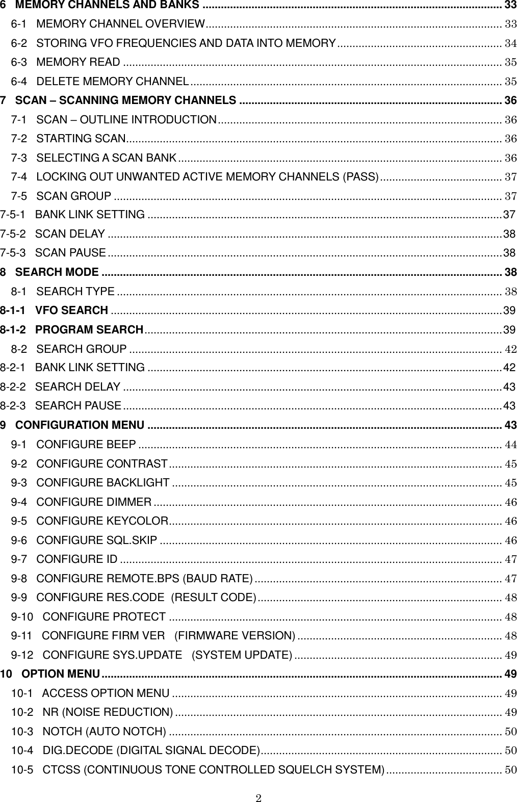
![12 VI (Voice inversion) --- not available for consumer version In AM, SAH, SAL, USB, LSB, CW modes AGCF --- AGC speed fast AGCM --- AGC speed medium AGCS --- AGC speed slow In auto mode, LSQ is selected for all AM modes and NSQ is selected for all FM modes. RF-G ---- Receiver’s manual gain control by the squelch knob. 21 NT Auto Notch 22 NR Noise reduction (in AM modes) 23 Key lock 24 PRI Priority receive 25 DUP Frequency offset 26 PAS In VFO search mode, pass frequencies stored In program search mode, pass frequencies stored in the current search bank In memory read mode, current receive frequency set to pass channel 27 HLD Delay time set to “HOLD” in VFO search mode, program search mode, memory scan mode. 28 FRE Free time set to other than “OFF” in VFO search mode, program search mode, memory scan mode 29 C PC remote control mode 30 SD card inserted in the slot and recognized (Note: Attenuator function is always activated automatically and no attenuator indicator is displayed on the LCD screen. The s-meter indicates reflecting attenuation level.) FRONT PANEL KEYS [F] The [F] (function) key is used to select secondary functions on the keypad. When pressed, “F” in reverse contrast appears on the top left corner of the LCD. The first function of the keys are printed on their surfaces; the secondary functions are printed in black directly above the corresponding key. To cancel the “F”, press this key again.](https://usermanual.wiki/AOR-USA/ARDV1/User-Guide-2608182-Page-13.png)
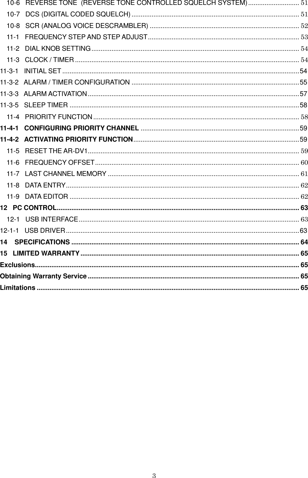
![13 LOCK Press and hold this key for two seconds to activate the key lock function. While activated, all front panel keys are disabled to prevent accidental misoperation of the receiver. However, volume and squelch controls remain operative. To cancel, press and hold this key again for two seconds. MONI Press and hold this key to force open squelch. While frequency offset activated, pressing this key will display the offset frequency. VFO In VFO mode, pressing this key will toggle between VFO-A and VFO-B. Press and hold this key for two seconds will activate VFO search. In other modes, press this key to return to VFO mode. SRCH In program mode, press this key to copy the current frequency to VFO-Z and continues receiving in VFO-Z. SCAN Initiate scan in the memory read mode. While in scan mode, press this key to copy the current frequency to VFO-Z and continues receiving in VFO-Z. In other modes, press this key to return to VFO mode. ● Start / Stop recording [1] Figure ONE for the numeric input of frequencies, bank, channel numbers, etc. [2] Figure TWO for the numeric input of frequencies, bank, channel numbers, etc. [3] Figure THREE for the numeric input of frequencies, bank, channel numbers, etc. [4] Figure FOUR for the numeric input of frequencies, bank, channel numbers, etc. [5] Figure FIVE for the numeric input of frequencies, bank, channel numbers, etc. [6] Figure SIX for the numeric input of frequencies, bank, channel numbers, etc. [7] Figure SEVEN for the numeric input of frequencies, bank, channel numbers, etc. [8] Figure EIGHT for the numeric input of frequencies, bank, channel numbers, etc. [9] Figure NINE for the numeric input of frequencies, bank, channel numbers, etc. [0] Figure ZERO for the numeric input of frequencies, bank, channel numbers, etc. [ENT] Confirm entry in most menus. In VFO mode, press this key to go to VFO-Z. In VFO search or program search mode, press this key to transfer the detected signal or stopped frequency to VFO-Z. The operation will be invalid while search is in progress. In memory read mode, press this key to transfer the current frequency to VFO-Z. In memory scan mode, press this key to transfer the detected signal or stopped frequency to VFO-Z. The operation will be invalid while scan is in progress. [PASS] This key is used to pass (skip over) unwanted active frequencies in VFO search mode and program search mode. In memory search mode, this key is used to on/off pass channel. [MODE] This key is to select the desired receive mode. Press this key to access the receive mode menu. Rotate the dial knob to select the desired mode. To accept the selection, press the [ENT] key. Holding this key for two seconds will go into digital auto mode.](https://usermanual.wiki/AOR-USA/ARDV1/User-Guide-2608182-Page-14.png)
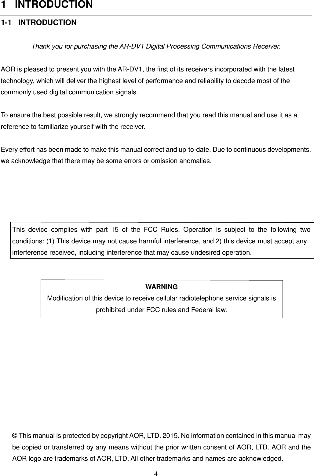
![14 [CLR] This key is used to cancel frequency entry during programming or exit from a menu. ▼ In VFO search mode or program search mode, pressing this key will change frequency upward or change search direction. In memory mode, pressing this key will move to next channel. In memory scan mode, pressing this key will change the scan direction or resuming scan. ▲ In VFO search mode or program search mode, pressing this key will change frequency downward or change search direction. In memory mode, pressing this key will move to next channel. In memory scan mode, pressing this key will change the scan direction or resuming scan. SECONDARY FUNCTION Key Press the [F], then press this key. Press and hold the [F] key for two seconds, then press this key VFO Move to VFO-A Set VFO SRCH Set search group N/A SCAN Set scan group Set memory bank ● Configure SD card N/A 1 Configure tone/code squelch Set voice squelch 2 Set frequency step N/A 3 Set clock N/A 4 Priority on/off Set priority 5 Set AGC (AM only) N/A 6 Set search bank N/A 7 Configuration menu N/A 8 Data editor N/A 9 Set option N/A 0 Set sleep timer N/A . Set offset N/A ENT N/A N/A PASS Set pass frequency Deselect pass requency MODE Set IF BW (Analog) N/A CLR Cancel entry N/A ▲ Change frequency upward in 10 times incremental N/A ▼ Change frequency downward in 10 times incremental N/A](https://usermanual.wiki/AOR-USA/ARDV1/User-Guide-2608182-Page-15.png)
![17 3-4 SQUELCH CONTROL To change the squelch level, rotate the squelch control knob clockwise to increase, and counterclockwise to decrease. The squelch level will be indicated on the LCD. After setting the squelch level, the LCD will return to original display. While squelch opens, “B” (busy) will appear in reverse contrast on the middle left of the LCD. 3-5 VFO SELECTION The AR-DV1 has three (3) VFOs identified as “VFO-A”, “VFO-B” and “VFO-Z” on the middle left of the LCD. The term VFO means ‘Variable Frequency Oscillator’, which today refers to a tunable data storage which contains frequency, step, step-adjust, attenuator etc. Pressing the [VFO] key each time will toggle between VFO-A and VFO-B. Note VFO-Z will be used for a different purpose. (VFO screen) (VFO screen with frequency database) (VFO-Z always displays frequency database)](https://usermanual.wiki/AOR-USA/ARDV1/User-Guide-2608182-Page-18.png)
![18 The AR-DV1 has an auto mode setting, which in most cases, will automatically select the proper receive mode and frequency steps. 3-5-1 TUNING FREQUENCY 3-5-1-1 ENTERING A FREQUENCY USING THE NUMERIC KEYPAD While in VFO mode, enter the required frequency using MHz format followed by the [ENT] key. (Example) Frequency entry of 81.3 MHz Press the [8] key. Press the [1] key. Press the [.] key. Press the [3] key. Press the [ENT] key. (Example) Frequency entry of 1.134 MHz (1134 kHz) Press the [1] key. Press the [.] key. Press the [1] key. Press the [3] key. Press the [4] key. Press the [ENT] key. Correcting frequency input Press the [CLR] key to delete the entry from the right hand side. 3-5-1-2 CHANGING FREQUENCY USING THE MAIN DIAL In VFO mode, the active VFO frequency may be ‘tuned’ in by using the tuning dial mounted on the right side of the front panel. Rotate the dial ‘clockwise’ to increase the frequency or 'counterclockwise’ to decrease the frequency. 3-5-1-3 CHANGING FREQUENCY USING [UP] KEY OR [DOWN] KEY The [▼] key and [▲] key provide a convenient way to change the frequency. The speed the receiver steps up and down will depend on the step size. In auto- mode, the step size, receiver mode, etc. are taken from the factory pre-programmed band plan but may be overridden at any time. Press the [▲] key to tune the receiver upward in the step size selected, and uses the [▼] key to tune the receiver downward in frequency.](https://usermanual.wiki/AOR-USA/ARDV1/User-Guide-2608182-Page-19.png)
![19 3-5-1-4 VFO COPY In VFO mode, press the [F] key and then the [PASS] key to copy between two VFO’s frequencies. (While receiving frequency on VFO-Z, copy it to VFO-B) The original VFO must always be VFO-Z. The destination can either be VFO-A or VFO-B, which can be selected by rotating the dial knob. To confirm selection, press the [ENT] key. 3-6 RECEIVE MODE Due to the necessities of signal bandwidth, channel occupancy, and transmission efficiency, different receive modes are used by various services. The receive mode and tuning step may vary throughout the world depending on the country’s international agreements and guidelines. For this reason, it is necessary to change these settings to monitor various transmissions. For your convenience, the receive mode and tuning step size have been pre-programmed into the AR-DV1 auto mode band plan data to simplify the operations of this receiver, especially while you familiarize yourself with its functions. If needed, you may override the defaults and select an alternative receive mode and tuning step on any frequency. AM – Amplitude Modulation Used by broadcast services throughout the world on long-, medium-, and shortwave. AM is also used by VHF airband, and UHF military airband. SAM – Synchronous AM Helps listen to SW (Shortwave) AM broadcast stations with fading signals. FM – There are two common types of FM (Frequency Modulation): NFM – Narrow Band Frequency Modulation Provides high quality communication for relatively short distance operations. FM uses a greater frequency bandwidth than other modes. NFM is the most common mode used above 30 MHz with the exception of the airbands. NFM is widely used on the VHF bands: VHF marine band, 2m amateur band, 70 cm amateur band, PMR (Private Mobile Radio) and utilities.](https://usermanual.wiki/AOR-USA/ARDV1/User-Guide-2608182-Page-20.png)
![20 In the absence of a signal, the background white noise may appear quite loud. For easier listening, the squelch control should be rotated clockwise until the background noise disappears; this should be carried out while no signal is present. The point at which the background noise is cancelled is known as the threshold point. Do not advance the squelch control more than necessary or the receiver will appear to be desensitized and weaker signals will be missed. WFM – Wide Band Frequency Modulation Used by VHF and UHF broadcast stations as excellent audio quality. This is available due to the relatively wide frequency bandwidth employed. Used only for local services such as VHF band stereo channels. LSB – Lower Side Band / A form of SSB (Single Side Band). Not intended for commercial use but is extensively used by Radio Amateurs on frequencies below 10 MHz. This assists in the separation of Commercial and Amateur users on traditionally shared bands and prevents them from speaking to each other. SSB is a very efficient method of transmission as the unwanted second sideband and carrier have been removed. This allows the full transmitter power to be employed in carrying useful information within the wanted sideband. As a result, greater distances are possible on SSB and a smaller frequency bandwidth is required than with most other modes. USB – Upper Side Band The same comments apply as for LSB. By convention, Radio amateurs also use USB above 10 MHz. CW - Continuous Wave Also referred as Carrier Wave or Morse Code. Commonly used on the short wave bands by radio amateurs toward the lower end of each band allocation. Some commercial use is still made by shipping etc although its use is being phased out due to the introduction of automated stations. 3-6-1 AUTO MODE SELECTION When in auto mode, the receive mode is automatically set to digital auto mode and analog receive mode is set to FM by the AR-DV1 microprocessor. To activate auto mode or reconfirm its selection while in VFO mode, press the [MODE] key. Then rotate the dial knob to select “AUTO” in the reverse contrast on the bottom of the LCD.](https://usermanual.wiki/AOR-USA/ARDV1/User-Guide-2608182-Page-21.png)
![21 Note: Auto-mode is cancelled as soon as the receive mode is changed. 3-6-2 RECEIVE MODE SELECTION Any receive mode may be selected at any frequency within the receiver’s frequency coverage. To access the receive mode menu, press the [MODE] key. The following modes are available: AUTO, FM, AM, SAH, SAL, USB, LSB, CW, DSTR, YAES, DMR, D-CR, dPMR, P-25, ALINC. AUTO mode AM mode DMR mode Rotate the dial knob to select the desired receive mode. Press the [ENT] key to confirm selection. 3-6-3 DIGITAL DATA DISPLAY When DIG.DECODE setting in the option menu (refer to: Section 10-4) is set to ON, data information for the received signal will be displayed on the bottom of the LCD.](https://usermanual.wiki/AOR-USA/ARDV1/User-Guide-2608182-Page-22.png)
![22 3-7 CHANGING THE FREQUENCY STEP The specification for channel occupancy, step (separation) and mode are decided by and allocated by the Departments of Governments following international discussions. The allocation of frequency bands are not the same all over the world and channel separation (step) varies from band to band. As an example, the channel separation (step) for the MW (medium wave) band in the U.S.A. is 10 kHz, and is 9 kHz in Europe and Japan. For above reasons, it is necessary to change the frequency step size according to the local band plan. The AR-DV1 has been pre-programmed at the factory with all the band plan data (specific to each market area) so that the AR-DV1 will automatically select the appropriate step size and mode for the frequency chosen. This greatly simplifies operation of the receiver while you are familiarizing yourself with all the functions. The pre-programming of step size may be manually overridden so you may choose alternative settings at will or when band plans are updated. If you wish to change the default tuning frequency step, press the [F] key and then the [2] key. The LCD will display the current frequency step in reverse contrast. Rotate the dial knob to select the desired step. To accept the displayed tuning step size, press the [ENT] key. 3-8 IF BANDWIDTH The IF bandwidth selects how SELECTIVE the receiver will be when monitoring signals off air. However, it is not simply a case of using the narrowest filter at all times; particular modes require differing amounts of bandwidth in order to operate. Otherwise the receive system will not produce intelligible sound. Correct receive mode and IF bandwidth must always be selected for optimum reception. If the bandwidth selection is too narrow, distortion or signal break-up may occur. If the bandwidth selection is too wide, adjacent interference may be encountered. For this reason, a selection of IF filter bandwidths are provided as standard.](https://usermanual.wiki/AOR-USA/ARDV1/User-Guide-2608182-Page-23.png)
![23 Typical examples of receive mode and IF bandwidth are: 200 kHz – VHF FM broadcast 30 kHz, 100 kHz – Wireless microphone, etc. (30 kHz for satellite FAX, too) 15 kHz – PMR, amateur band, etc. FM 6 kHz may also be used 6 kHz – VHF/UHF airband, short wave broadcast, medium & long wave, PMR, etc. 3 kHz – Short wave amateur band, short wave utility such as oceanic airband etc. 500 Hz – Morse code used by radio amateurs and some marine traffic on short wave An appropriate IF filter is automatically selected when auto mode is selected. However any combination of IF filter and receive mode is possible in the manual mode. When you have manually selected an IF filter bandwidth, auto mode will be cancelled, but the receive mode, frequency step, etc will be retained until they are changed manually. 3-8-1 MANUALLY SELECTING IF BANDWIDTH Press the [F] key and then the [MODE] key. Select a new bandwidth from the list by rotating the dial knob. To accept the new bandwidth selection, press the [ENT] key. Mode Selectable band width (kHz) Default (kHz) FM 200, 100, 30, 15, 6 15 AM 15, 8, 5.5, 3.8 8 SAH, SAL 5.5, 3.8 5.5 USB, LSB 2.6, 1.8 2.6 CW 0.5, 0.2 0.5 Selectable band width Note: The IF band width will be selected automatically in digital mode.](https://usermanual.wiki/AOR-USA/ARDV1/User-Guide-2608182-Page-24.png)
![24 4 ADDITIONAL SETTINGS 4-1 AGC (AUTOMATIC GAIN CONTROL) AGC is available in following AM modes: AM, SAH, SAL, USB, LSB and CW To change the AGC parameter setting, press the [F] key and then the [5] key. Select a new AGC parameter from the list of “AGCS (FAST)”, “AGCM (MIDDLE)”, “AGCS (SLOW)”. by rotating the dial knob. To accept the new AGC parameter, press the [ENT] key. Usually, FAST is used to receive CW, MEDIUM for AM and FM, and SLOW for SSB mode. However, this option cannot be configured in FM mode. When AGC is set to RF-G, the RF gain control can be adjusted by the squelch knob. 4-2 ATTENUATOR Activating the attenuator reduces signal to the RF input stages of the AR-DV1 in order to prevent overloading due to connection to an external antenna or when the receiver is used close to strong transmissions. The AR-DV1 has the automatic attenuator function. 4-3 RF GAIN To activate the manual RF gain control, press the [F] key and then the [5] key.](https://usermanual.wiki/AOR-USA/ARDV1/User-Guide-2608182-Page-25.png)
![25 Rotate the dial knob to select “RF-G”. To change the RF gain manually, rotate the squelch knob. To cancel the manual RF gain control, repeat above steps. (Note: The manual RF gain control is not available while the receiver selects AGC mode.) 4-4 KEYLOCK Press the [LOCK] key to activate the key lock function. While activated, all front panel keys are disabled to prevent accidental misoperation of the receiver. However, the volume and squelch controls remain operative. 4-5 VFO SETTING To go to the VFO setting menu, press the [F] key. Then press and hold the [VFO] key for two seconds. Following screen will appear.](https://usermanual.wiki/AOR-USA/ARDV1/User-Guide-2608182-Page-26.png)
![26 4-5-1 VFO SEARCH DELAY The delay parameter affects the time the AR-DV1 will remain on an active frequency in VFO search mode once the received signal has disappeared and the squelch is closed. This is particularly useful for customizing how long the receiver will wait for a reply before continuing to search. The parameter ranges are off, hold and 0.1 to 9.9 seconds in 0.1 second incremental. (Default: 2.0 seconds) To set the delay parameter, perform the following steps: 1. On the VFO search setting screen, use the [▼] key or [▲] key to select [DELAY]. 2. Rotate the dial knob to select the delay time. 3. If “HOLD” is selected, the receiver will stop searching 4. To confirm entry, press the [ENT] key. To set other parameters, press the [▼] key. 4-5-2 VFO SEARCH FREE (PAUSE) The search free (pause) parameter determines how long the receiver will remain on an active frequency before resuming searching even if the signal is still busy. Search free helps keep you from having to manually intervene to force the search to continue or use frequency lockout (pass). The parameter ranges are off and 1 to 60 seconds. When the parameter is set to off, the receiver remains on the busy frequency until the received signal disappears or the frequency is changed. To set the parameter, perform the following steps: 1. In the VFO search screen, use the [▼] key or [▲] key to select [FREE]. 2. Rotate the dial knob to set scan pause parameter (between 1 ~ 60 or off). To set search free to off (zero), press the [PASS] key or enter “0” from the numeric keypad. 3. To confirm entry, press the [ENT] key. To set other parameters, press the [▼] key. 4-5-3 VFO SEARCH STORE This menu is to select ON or OFF to save received frequencies in VFO search mode onto memory bank 39. (Default: OFF) To set the parameter, perform the following steps: 1. In the VFO search screen, use the [▼] key or [▲] key to select [STORE]. 2. Rotate the dial knob to select parameter ON or OFF.](https://usermanual.wiki/AOR-USA/ARDV1/User-Guide-2608182-Page-27.png)
![27 3. To confirm entry, press the [ENT] key. To set other parameters, press the [▼] key. 4-5-4 DEL.BK39 This menu is to select ON or OFF to delete all data on memory bank 39 in VFO search mode. (Default: OFF) To set the parameter, perform the following steps: 1. In the VFO search screen, use the [▼] key or [▲] key to select [DEL.BK39]. 2. Rotate the dial knob to select parameter ON or OFF. 3. To confirm entry, press the [ENT] key. To set other parameters, press the [▼] key. 4-6 NOISE SQUELCH AND LEVEL SQUELCH Press and hold the SQL knob for two seconds and squelch setting will be displayed. NSQ (Noise Squelch) : Available in FM mode NSQ(A) : Noise squelch in auto mode LSQ (Level Squelch) : Level squelch LSQ(A): Level squelch in auto mode Press the [ENT] key to confirm entry. Alternatively, press the [CLR] key to abort. To set the squelch level, press the SQL knob and rotate the knob clockwise until back ground noise distinguished. 4-7 VOICE SQUELCH When the voice squelch function is activated, the audio will be muted on unwanted voice signals. The squelch parameter ranges are OFF and 1 ~ 7. (Default: 4) To set the voice squelch parameter, perform the following steps: 1. Press the [F] key. Then press and hold the [1] key for two seconds. 2. The voice squelch setting screen will appear.](https://usermanual.wiki/AOR-USA/ARDV1/User-Guide-2608182-Page-28.png)
![28 3. Rotate the dial knob to select set voice squelch function OFF or ON. (Default: OFF) 4. To select OFF, press the [ENT] key. It will return to normal display. 5. If ON is selected, press the [▼] key to select “DELAY” parameter in reverse contrast. 6. The DELAY parameter is to set the delay time before activating voice squelch in 0.1 second increment. (Default: 020 --- 2 seconds) 7. Press the [▼] key to select “LEVEL” parameter in reverse contrast. 8. Rotate the dial knob to set voice level parameter (between 1 ~ 7 or OFF). (Default: 4) 9. To confirm entry, press the [ENT] key. Alternatively, press the [CLR] key to cancel entry. 5 ADVANCED FUNCTIONS 5-1 MANAGING A SD CARD The AR-DV1 has a built-in SD memory card interface used for voice recording and/or memory management. To access the SD card managing menu, perform the following steps: 1. Insert a SD memory card with a printed label upward facing the slot on the front panel until you can hear a click. 2. Wait until “ ” icon appears on the right middle of the LCD. 3. Press the [F] key and then the [●] (SD) key. The following screen will appear. (Example) FREE: 00535MB/31250MB 000535MB --- Space free, 31250MB ----- Total size (Note: If the SD card is not inserted into the slot, above screen will not appear.) 5-3-1 SD CARD INFORMATION After performing above steps, press the [ENT] key while “VIEW->” is selected in reverse contrast.](https://usermanual.wiki/AOR-USA/ARDV1/User-Guide-2608182-Page-29.png)
![29 While reading from the SD card, the following screen will appear. The file list of the SD card will appear. (1) Firmware version (2) Recorded files (3) Search bank data (4) Scan group data To exit the SD card configuration menu, press the [CLR] key. 5-3-2 BACKUP DATA TO A SD CARD To backup memory channel, search bank contents, receiver’s configuration data of the AR-DV1 to a SD card, perform the following steps: 1. Insert a SD memory card with a printed label upward facing the slot on the front panel until you can hear a click. 2. Wait until “ ” icon appears on the right middle of the LCD. 3. Press the [F] key and then the [●] (SD) key. The following screen will appear. (Example) 4. Press the [▼] key to move the cursor to [BACKUP] parameter in reverse contrast. 5. Press the [ENT] key while “SET->” is selected in reverse contrast.](https://usermanual.wiki/AOR-USA/ARDV1/User-Guide-2608182-Page-30.png)
![30 6. The following backup menu will appear. SRCH BANK (Search Bank) : Backup all search bank data --- File name: SRCHBK.CSV SRCH GRP (Search Bank Group) : Backup all search bank group data --- File name: SRCHGRP.CSV MEM CH (Memory Channel): Backup memory channel data --- File name: MEMCH.CSV SCAN GRP (Scan Group): Backup all scan bank group data --- File name: SCANGRP.CSV SYSTEM : Backup Receiver’s configuration data --- File name: SYSTEM.CSV Select the category and press the [ENT] key to backup data. 5-3-3 RESTORE DATA FROM SD CARD 1. Insert a new SD memory card with a printed label upward facing the slot on the front panel until you can hear a click. 2. Wait until “ ” icon appears on the right middle of the LCD. 3. Press the [F] key and then the [●] (SD) key. The following screen will appear. (Example) 4. Press the [▼] key to move the cursor to [LIST] parameter in reverse contrast. 5. Press the [ENT] key. 6. The file list of the SD card will be displayed. The file list of the SD card will appear.](https://usermanual.wiki/AOR-USA/ARDV1/User-Guide-2608182-Page-31.png)
![31 (1) Firmware version (2) Recorded files (3) Search bank data (4) Scan group data 7. Select the desired bakup file to be restored. 8. Press the [ENT] key. Restore will start. To restore data, entire data or specific data may be selected by using a PC in advance. 9. The prefix of file name can be used any characters or numbers, however, the extension must be always “.csv”. If there is an error of the file contents, an error message will be displayed and quit restoring. 5-3-4 RECORDING AUDIO To record audio of the AR-DV1 on the SD memory card, perform the following steps: 1. Insert a SD memory card with a printed label upward facing the slot on the front panel until you can hear a click. 2. Wait until “ ” icon appears on the right middle of the LCD. 3. Press the [●] (SD) key. The [R] icon in reverse format will appear on the top left of the LCD. 4. To stop recording, press the [●] (SD) key again. The [R] icon will disappear. The file name will be MMDDHHmm.WAV and saved in wav format. The recorded files contain the recorded time, receiving frequency, receive mode, signal strength and receive mode.](https://usermanual.wiki/AOR-USA/ARDV1/User-Guide-2608182-Page-32.png)
![32 . Example: 03281803.WAV --- Record started on March (03) 28th at 18:03 If the file name already exists, it will be overwritten. 5-3-6 PLAYBACK AUDIO FROM SD CARD To playback recorded audio of the AR-DV1 on the SD memory card, perform the following steps: 1. Insert a SD memory card with a printed label upward facing the slot on the front panel until you can hear a click. 2. Wait until “ ” icon appears on the right middle of the LCD. 3. Press the [F] key and then the [●] (SD) key. The following screen will appear. (Example) 4. Press the [ENT] key while “VIEW->” is selected in reverse contrast. While reading from the SD card, the following screen will appear. The file list of the SD card will appear. (1) Firmware version (2) Recorded files (3) Search bank data (4) Scan group data 5. Using the [▲] key or [▼] key, select the recorded file (in wav format).](https://usermanual.wiki/AOR-USA/ARDV1/User-Guide-2608182-Page-33.png)
![33 6. Press the [ENT] key. The audio file will playback. “P” in reverse contrast will appear on the top left of the LCD. To stop, press any key. When finished, the screen will return to the file list menu. 6 MEMORY CHANNELS AND BANKS It is convenient to store commonly used frequencies into a memory channel along with mode etc, as this saves having to key the data in over and over again. Memory read is very straightforward and quick when compared to retyping all data. 6-1 MEMORY CHANNEL OVERVIEW Think of memory channels as pages in a notebook each of which is numbered to identify it. Data may be written to each new page (memory channel) and each page may be overwritten with new data, so they can be used over and over again. The AR-DV1 has 2,000 memory channels and one priority channel. Each memory channel may hold: One receive frequency Receive mode Tuning step Text comment of up to 12 characters The alphanumeric comment may be used to ease identification at a later date. The 2,000 memory channels are divided into 40 banks, and each bank has 50 channels. The memory banks are identified by the first BANK number 0, 1, 2, 3, …, 48, 49 and the individual channels are numbered from 00 to 49. (Example): “1234” is the location: memory bank “12” and memory channel “34” The data contents of memory and search banks are held in an EEPROM so that no backup battery is required for memory retention. The stored data may be quickly and easily recalled, changed or deleted using the memory recall and delete functions. Note: When the receiver is switched OFF, all VFO data will be automatically stored into EEPROM memory storage.](https://usermanual.wiki/AOR-USA/ARDV1/User-Guide-2608182-Page-34.png)
![34 6-2 STORING VFO FREQUENCIES AND DATA INTO MEMORY The process to save a displayed VFO frequency to memory is as follows: 1. In VFO mode, select the required frequency, mode, etc. 2. Press and hold the [ENT] key for two seconds. The AR-DV1 will automatically find the next available vacant memory channel. 3. Using the keypad, select the desired memory location (bank and channel). 4. Add a text comment (optional) or delete an existing comment. 5. Press the [ENT] key to exit the menu and save the data to the specified memory location. (Example) Storing the frequency of 145.000 MHz into memory bank “3” location “25” (0325) while in VFO mode. If a mistake is made during programming, press the [CLR] key to abort entry and return to VFO mode. 1. Start by selecting VFO mode, then enter the frequency of 123.500 MHz, “mode and step size” are set to the default auto mode. a) Press the [VFO] key to set the AR-DV1 into the VFO mode. b) Press the [1] key. c) Press the [4] key. d) Press the [5] key. e) Press the [.] (decimal) key. f) Press the [0] key. g) Press the [ENT] key. 2. Press and hold the [ENT] key for two seconds. 3. The bank title (BANK BANK__[BK.TITLE]) and channel title (CH CH__[CH.TITLE]) will appear alternatively on the bottom of the LCD. If those titles are already registered, those titles will be displayed. 4. Using the numeric keypad, enter the bank and channel number. (Four digits total) 5. Enter the title for the memory channel. A maximum of 12 characters may be added to each memory channel. 6. Press the [▼] key to move the cursor.](https://usermanual.wiki/AOR-USA/ARDV1/User-Guide-2608182-Page-35.png)
![35 7. To protect/unprotect the memory channel, rotate the dial to select ON (protect) or OFF (unprotect). 8. Press the [ENT] key to complete memory registration. 6-3 MEMORY READ Once frequency and mode data have been stored into a memory location, retrieval is quick and simple. There are 40 banks (#00 ~ 39), 50 channels per bank with the AR-DV1. (Sample of memory read screen) 1. If you already know the memory bank and memory channel, using the numeric keyad, enter the memory bank number (two digits) and memory channel number (two digits). Then press the [ENT] key. (Above screen shows memory bank #05 and memory channel #00.) 2. The AR-DV1 will monitor whatever memory channel you enter into memory read. 3. While in memory read, changing the receive mode or frequency steps, etc. will automatically update the memory contents. 4. If you don’t want to make changes, set memory protect to ON to avoid overwriding the contents. 5. To return to VFO mode, press the [VFO] key. 6-4 DELETE MEMORY CHANNEL To delete memory channels, perform the following steps: 1. In the memory read mode, press the [F] key and then the [CLR] key. 2. Following screen will appear. 3. To delete the selected memory channel, press the [ENT] key. Alternatively, press the [CLR] key to cancel entry. 4. After deleting the memory channel, it will return to VFO-A mode. (Note: If the memory channel is write protected, it will not be deleted.)](https://usermanual.wiki/AOR-USA/ARDV1/User-Guide-2608182-Page-36.png)
![36 7 SCAN – SCANNING MEMORY CHANNELS The AR-DV1 has a scan mode whereby the contents stored in the memory channels are automatically recalled and monitored very quickly for activity – scanned. (Note: It is important that you do not confuse SCAN and SEARCH modes.) SEARCH mode (covered later in this manual) automatically tunes the receiver through all frequencies between two specified frequency limits looking for active frequencies. 7-1 SCAN – OUTLINE INTRODUCTION During scan, the AR-DV1 automatically recalls memory channels which contain data in numeric order and monitors looking for activity. When an ‘active’ memory channel is located (when a signal is found and the squelch is open), the AR-DV1 will temporarily stop scanning. 7-2 STARTING SCAN Presuming that some memory channels are programmed with data, start the scan process with one press of the [SCAN] key. Once the scan process has been started, a bank number will be also be displayed representing the current bank. Ensure that the squelch is set to threshold point so that background noise is cancelled and the squelch closes (otherwise scan will not operate). When scan has been selected, only the currently displayed memory bank which contains data will be scanned, and receive mode and frequency are not important. Any memory channels which contain no data (empty) will be ignored and skipped. 7-3 SELECTING A SCAN BANK The memory bank identifier (such as “03”) will be displayed on the middle of the LCD. If more than one memory channel is programmed into the current memory bank, and when an ‘active’ channel has been located (busy, so the squelch opens), the scan process will temporarily pause on the active channel. The memory location (such as “25”) will be displayed along with any accompanying text. To select another memory bank for scanning, rotate the dial knob or enter the two digits of the memory bank number from the numeric keypad.](https://usermanual.wiki/AOR-USA/ARDV1/User-Guide-2608182-Page-37.png)
![37 To exit from scan mode, press the [VFO] key. 7-4 LOCKING OUT UNWANTED ACTIVE MEMORY CHANNELS (PASS) It is possible to lock out (PASS) unwanted memory channels while in scan mode. This is useful to eliminate unwanted permanent transmissions. It is important to understand the PASS function before taking action or transmissions may be missed. In memory read mode or while stopped on an unwanted frequency, press the [PASS] key. Pressing the [PASS] key again on the same memory channel will de-select pass channel. The scan process will resume. It will appear that all channels are still scanned, however, locked out channels will be ‘skipped’, the scan will not stop on locked out channels. 7-5 SCAN GROUP The AR-DV1 has 20 scan groups to be used with the bank link function and other functions. The following parameters can be registered for each of the scan groups. Bank link setting Scan pause Scan delay To set up scan group, press the [F] key and then the [SCAN] key. 7-5-1 BANK LINK SETTING 1. There are 10 scan group and the group number can be selected between 0 ~ 9. Rotate the dial knob to select the scan group. Then press the [▼] key to go to the bank select menu. You can also use the numeric keypad to select the scan group. To return to scan group selection menu, press the [▲] key.](https://usermanual.wiki/AOR-USA/ARDV1/User-Guide-2608182-Page-38.png)
![38 2. Rotate the dial knob select the bank link group. Pressing the [PASS] key will toggle the link on and off. 3. Press the [ENT] key to complete setting or press the [CLR] key to abort entry. 7-5-2 SCAN DELAY The scan delay parameter affects the time the AR-DV1 will remain on an active channel in the scan mode once the received signal has disappeared and the squelch is closed. This is particularly useful for customizing how long the receiver will wait for a reply before continuing to scan. The parameter ranges are off, hold and 0.1 to 9.9 seconds in 0.1 second incremental. (Default: 2.0 seconds) To set the scan delay parameter, perform the following steps: 1. On the scan group setting screen, use the [▼] key or [▲] key to select [DELAY]. 2. Rotate the dial knob to select the scan delay. 3. If “HOLD” is selected, the receiver will stop scanning 4. To confirm entry, press the [ENT] key. To set other parameters, press the [▼] key. 7-5-3 SCAN PAUSE The scan pause parameter determines how long the receiver will remain on an active channel before resuming scanning even if the channel is still busy. Scan pause helps keep you from having to manually intervene to force the scan to continue or use channel lockout (pass). The parameter ranges are off and 1 to 60 seconds. When the parameter is set to off, the receiver remains on the busy channel until the received signal disappears or the memory channel is changed. To set the scan pause parameter, perform the following steps: 1. On the scan group setting screen, use the [▼] key or [▲] key to select [FREE]. 2. Rotate the dial knob to set scan pause parameter (between 1 ~ 60 or off). To set scan pause to off (zero), press the [PASS] key or enter “0” from the numeric keypad. 3. To confirm entry, press the [ENT] key. 8 SEARCH MODE In search mode, the AR-DV1 is programmed to automatically tune between two specified frequency limits looking for activity. Before activating search mode, the squelch must be set to threshold where the background noise disappears. 8-1 SEARCH TYPE The AR-DV1 is equipped with VFO search, program search.](https://usermanual.wiki/AOR-USA/ARDV1/User-Guide-2608182-Page-39.png)
![39 VFO SEARCH = Search between two VFO frequencies PROGRAM SEARCH = Search between user preprogrammed frequency limits 8-1-1 VFO SEARCH The VFO search is the easiest way of searching without programming. When the VFO-A is selected as a primary VFO, the AR-DV1 will search between two frequencies on VFO-A and VFO-B with receive mode, frequency step set in the VFO-A. VFO search screen To activate the VFO search, perform the following steps: 1. In VFO mode, press and hold either the [VFO] key, [▼] key, or [▲] key for more than two seconds. The search process starts. The search direction can be changed by rotating the dial knob or pressing the [▼] key or [▲] key. 2. When the receiver stops on a busy frequency, you can resume manual search by rotating the dial knob or pressing the [▼] key or [▲] key. 3. While the receiver stops on receive signal, pressing the [PASS] key will register the receive frequency to the VFO pass frequencies. This frequency will be locked out (passed) after the next search and not be received. 4. To stop the VFO search, press the [VFO] key. To delete pass frequencies, perform the following steps: 1. While stopped on unwanted frequency, press and hold the [PASS] key for two seconds. The following screen will appear. 2. Rotate the dial knob to select the desired frequencies to be deleted. 3. To delete all pass frequencies, press the [F] key and then the [PASS] key. 8-1-2 PROGRAM SEARCH The AR-DV1 has 40 program search banks (referred to simply as search banks) which can be programmed with specific parameters: LO (lower) start frequency HI (upper) stop frequency Receive mode (or set to AUTO MODE)](https://usermanual.wiki/AOR-USA/ARDV1/User-Guide-2608182-Page-40.png)
![40 Text comment The program search banks are identified by numbers (00 ~ 39). To help with identification, each bank may be labeled with an alphanumeric text comment. 8-1-2-1 STARTING PROGRAM SEARCH Presuming that data is already stored into a search bank. Press the [SRCH] key to start the program search process. “SER” icon will be displayed on the top left of the LCD. As long as the squelch is closed, the search process will start from the lower frequency limit and will progress toward the upper frequency limit. When the program limit is reached, the search loops around and starts the process again. Note: If no search banks have been programmed, the search will not operate. 8-1-2-2 REVERSING THE SEARCH DIRECTION To reverse the search direction, rotate the dial knob or press the [▼] key or the [▲] key. This is useful to enable you to search back over an interesting point of the search process. 8-1-2-3 FORCING THE SEARCH TO RESUME If the AR-DV1 stops on an unwanted busy frequency, rotate the dial knob or press the [▼] key or [▲] key to force the search process to resume from the current frequency displayed. 8-1-2-4 STOPPING THE SEARCH While the search process is in progress (not stopped), press the [VFO] key (displaying the data on-screen before search was started). 8-1-2-5 SELECTION OF SEARCH BANK There are 40 search banks. While searching, rotate the dial knob to step through search banks which contain data. If no data is programmed in the nominated search bank, the next bank containing valid data will be used. 8-1-2-6 PROGRAMMING A SEARCH BANK Each of the 40 search banks may be programmed with different frequency limits, receive modes, etc. To program a search bank, perform the following steps: 1. Press the [F] key and then the [6] key to access the search program menu. The next available or vacant search bank number will be displayed. 2. Rotate the dial knob to select the search bank to program or overwrite. You may use the keypad to enter 2 digits number to select the search bank number. 3. Press the [▼] key to move the cursor downward to select [L.FRQ.]](https://usermanual.wiki/AOR-USA/ARDV1/User-Guide-2608182-Page-41.png)
![41 Using the numeric keypad, enter the lower frequency limit in MHz format. 4. Press the [ENT] key. After an entry of the frequency, the cursor will automatically move downward to [U.FRQ.] 5. Using the numeric keypad, enter the upper frequency limit in MHz format. 6. Press the [ENT] key. After an entry of the frequency, the cursor will automatically move downward to [STEP]. 7. Rotate the dial knob to select the frequency step. You may use the keypad for entry. In this setting, pressing the [PASS] key will move to step adjustment setting screen. (optional) 8. Press the [▼] key to move to [DIG.MODE] on the next page. 9. In [DIG.MODE], selecting parameter other than [OFF] will automatically select FM mode in the next [ANA.MODE] menu and analog mode setting will be skipped. 10. Press the [▼] key to move the cursor downward to select [ANA.MODE]. 11. This selection is available only when [DIG.MODE] is set to [OFF]. 12. Rotate the dial knob to select the analog mode. 13. Press the [▼] key to move the cursor downward to select [TITLE]. 14. Using the keypad, enter the search bank title. 15. Press the [▼] key to move the cursor downward to select [PROTECT]. 16. Rotate the dial knob to select ON or OFF. 17. Press the [ENT] key to confirm entry or press [CLR] to abort entry. 8-1-2-7 LOCKING OUT UNWANTED ACTIVE FREQUENCIES (PASS) It is possible to lock out (pass) unwanted frequencies while in the program search mode. This is useful to eliminate unwanted permanent transmissions. Up to 30 pass frequencies can be registered for each search bank. A total of 1200 pass frequencies can be registered in the AR-DV1. It is important to understand the pass function before taking action or transmissions may be missed. To pass the frequency in search mode, press the [PASS] key while stopped on an unwanted frequency. 8-1-2-8 DELETING PASS FREQUENCIES To delete pass frequencies, perform the following steps: 1. While stopped on unwanted frequency, press and hold the [PASS] key for two seconds. The following screen will appear.](https://usermanual.wiki/AOR-USA/ARDV1/User-Guide-2608182-Page-42.png)
![42 2. Above screen displays the last selected search bank. Rotate the dial knob to select the desired search bank that contains the frequency to be deleted. 3. Press the [▼] key and then the [PASS] key to delete pass frequency. 4. To delete all pass frequencies in the current search bank, press the [F] key and then the [PASS] key. 8-1-2-9 DELETING SEARCH BANK To delete search bank, perform the following steps: 1. While on program search receive mode, press the [F] key and then the [CLR] key. The following screen will appear. 2. Rotate the dial knob to select the desired search bank to be deleted. 3. Press the [ENT] key. Alternatively, press the [CLR] key to cancel entry. After deleting the search bank, it will return to VFO-A mode. 8-2 SEARCH GROUP The AR-DV1 has 20 search groups to be used with the bank link function and other functions. The following parameters can be registered for each of the search groups. Bank link setting Search pause Search delay To set up search group, press the [F] key, then press the [SRCH] key. 8-2-1 BANK LINK SETTING 1. There are 10 search group and the group number can be selected between 0 ~ 9.](https://usermanual.wiki/AOR-USA/ARDV1/User-Guide-2608182-Page-43.png)
![43 Rotate the dial knob to select the search group. Then press the [▼] key to go to bank select menu. You can also use the numeric keypad to select the search group. To return to scan group selection menu, press the [▲] key. 2. Rotate the dial knob select the bank link group. Pressing the [PASS] key will toggle the link ON and OFF. 3. Press the [ENT] key to complete setting or press the [CLR] key to abort entry. 8-2-2 SEARCH DELAY The search delay parameter affects the time the AR-DV1 will remain on an active channel in the search mode once the received signal has disappeared and the squelch is closed. This is particularly useful for customizing how long the receiver will wait for a reply before continuing to search. The parameter ranges are off, hold and 0.1 to 9.9 seconds in 0.1 second incremental. (Default: 2.0 seconds) To set the search delay parameter, perform the following steps: 1. On the search group setting screen, use the [▼] key or [▲] key to select [DELAY]. 2. Rotate the dial knob to select the search delay. 3. If “HOLD” is selected, the receiver will stop searching 4. To confirm entry, press the [ENT] key. To set other parameters, press the [▼] key. 8-2-3 SEARCH PAUSE The search pause parameter determines how long the receiver will remain on an active frequency before resuming searching even if the channel is still busy. Search pause helps keep you from having to manually intervene to force the search to continue or use channel lockout (pass). The parameter ranges are off and 1 to 60 seconds. When the parameter is set to off, the receiver remains on the busy frequency until the received signal disappears or the search frequency is changed. To set the search pause parameter, perform the following steps: 1. On the search group setting screen, use the [▼] key or [▲] key to select [FREE]. 2. Rotate the dial knob to set search pause parameter (between 1 ~ 60 or off). To set search pause to off (zero), press the [PASS] key or enter “0” from the numeric keypad. 3. To confirm entry, press the [ENT] key. 9 CONFIGURATION MENU The configuration menu is used to set fundamental operating parameters and other variables which do not appear in any menu heading. To access the configuration menu, press the [F] key and then the [7] key.](https://usermanual.wiki/AOR-USA/ARDV1/User-Guide-2608182-Page-44.png)
![44 CONFIGURATION MENU 1/4 BEEP Confirmation tone CONTRAST Adjust LCD contrast BACKLIGHT LCD illumination DIMMER LCD dimmer CONFIGURATION MENU 2/4 KEY COLOR Keypad illumination color SQL.SKIP Record audio continuously/ stop while squelch closes ID Set receiver’s identification number REMOTE.BPS Data communication speed CONFIGURATION MENU 3/4 RES.CODE PROTECT FIRM VER Display the firmware of the receiver SER. Serial number of the receiver CONFIGURATION MENU 4/4 SYS.UPDARE Firmware update 9-1 CONFIGURE BEEP The AR-DV1 emits confirmation ‘beeps’ while the keypad is used to indicate correct operation. The volume of the beep is independent of the volume control and can be separately defined. It is recommended that the beep function be enabled to confirm data entry. To access the configuration menu, press the [F] key and then the [7] key. Press the [▼] key to select “BEEP” parameter in reverse contrast. Rotate the dial knob to select the desired beep level between the range of OFF and 0 to 7 (loudest). (Default: 5)](https://usermanual.wiki/AOR-USA/ARDV1/User-Guide-2608182-Page-45.png)
![45 Press the [ENT] key to accept the entry and return to a standard display. Alternatively, press the [CLR] key to abort entry. Or, press the [▼] key to move to the next item on the configuration menu. 9-2 CONFIGURE CONTRAST The AR-DV1 is equipped with variable LCD contrast which is adjustable in 64 steps to provide the best visibility under different viewing angles. The default setting for contrast is 25. To access the configuration menu, press the [F] key and then the [7] key. Press the [▼] key to select “CONTRAST” parameter in reverse contrast. Rotate the dial knob to select the desired setting between the range of 00 ~ 63. Press the [ENT] key to accept the entry and return to a standard display. Alternatively, press the [CLR] key to abort entry. Or, press the [▼] key to move to the next item on the configuration menu. 9-3 CONFIGURE BACKLIGHT The AR-DV1 is equipped with high intensity LEDs to illuminate the LCD when operating in areas of low level lighting. The backlight lamp may be configured in three ways: OFF The lamp remains permanently extinguished. This is useful when used in areas of high light levels. ON The lamp will continuously illuminate the LCD and keypad. AUTO This is default setting. The lamp will automatically illuminate the LCD and keypad when the front panel is used or squelch opens. The lamp will remain illuminated for five seconds after the last key is pressed. Then it will extinguish. To access the configuration menu, press the [F] key and then the [7] key. Press the [▼] key to select “BACKLIGHT” parameter in reverse contrast. Rotate the dial knob to select the desired setting. Press the [ENT] key to accept the entry and return to a standard display. Alternatively, press the [CLR] key to abort entry. Or press the [▼] key to move to the next item on the configuration menu.](https://usermanual.wiki/AOR-USA/ARDV1/User-Guide-2608182-Page-46.png)
![46 9-4 CONFIGURE DIMMER The AR-DV1 is equipped with high intensity LEDs to illuminate the LCD when operating in areas of low level lighting. The dimmer function adjusts the brightness of the backlight lamp and may be configured in two ways: OFF This is default setting. The lamp illuminate normally. ON The brightness of be decreased by approximately 50%. However, the brightness of the keypad will not be changed. To access the configuration menu, press the [F] key and then the [7] key. Press the [▼] key to select “DIMMER” parameter in reverse contrast. Rotate the dial knob to select the desired setting. Press the [ENT] key to accept the entry and return to a standard display. Alternatively, press the [CLR] key to abort entry. Or, press the [▼] key to move to the next item on the configuration menu. 9-5 CONFIGURE KEYCOLOR The AR-DV1 is equipped with high intensity LEDs to illuminate the keypad. The color of the keypad may be configured in nine ways: OFF The keypad will not be illuminated all the time. AUTO The color of the backlit keypad will be selected automatically. BLUE, RED, MAGENTA, GREEN, CYAN, YELLOW, ORANGE To access the configuration menu, press the [F] key, and then press the [7] key. Press the [▼] key to select “KEYCOLOR” parameter in reverse contrast. Rotate the dial knob to select the desired setting. Press the [ENT] key to accept the entry and return to a standard display. Alternatively, press the [CLR] key to abort entry. Or, press the [▼] key to move to the next item on the configuration menu. 9-6 CONFIGURE SQL.SKIP The squelch skip menu is used to configure the SD card voice recording when squelch is open or closed. When squelch skip is set to OFF, the recording process will take place even when the squelch is closed and no audio signal is present.](https://usermanual.wiki/AOR-USA/ARDV1/User-Guide-2608182-Page-47.png)
![47 When squelch skip is set to ON, the recording process will take place only when the squelch is opened and an audio signal is present. This is default setting. To access the configuration menu, press the [F] key and then the [7] key. Press the [▼] key to select “SQL.SKIP” parameter in reverse contrast. Rotate the dial knob to select the desired setting. Press the [ENT] key to accept the entry and return to a standard display. Alternatively, press the [CLR] key to abort entry. Or, press the [▼] key to move to the next item on the configuration menu. 9-7 CONFIGURE ID It is possible to change the receiver’s Identification address when multiple units are connected to the same port. It is possible to connect up to 99 units at once while each receiver is assigned a different address. The value is adjustable between 00 ~ 99. The default setting is 00. To access the configuration menu, press the [F] key and then the [7] key. Press the [▼] key to select “ID” parameter in reverse contrast. Rotate the dial knob to select the desired setting between the range of 00 ~ 99. Press the [ENT] key to accept the entry and return to a standard display. Alternatively, press the [CLR] key to abort entry. Or, press the [▼] key to move to the next item on the configuration menu. 9-8 CONFIGURE REMOTE.BPS (BAUD RATE) The Remote BPS Set menu is used to configure the communication port control settings as it is important that they exactly match those of an associated computer connection. To access the configuration menu, press the [F] key and then the [7] key. Press the [▼] key to select “REMOTE.BPS” parameter in reverse contrast. Rotate the dial knob to select the desired baud rate from 9600, 19200, 38400, 57600, 115200 bps. The default setting is 115200 bps. Press the [ENT] key to accept the entry and return to a standard display.](https://usermanual.wiki/AOR-USA/ARDV1/User-Guide-2608182-Page-48.png)
![48 Alternatively, press the [CLR] key to abort entry. Or, press the [▼] key to move to the next item on the configuration menu. 9-9 CONFIGURE RES.CODE (RESULT CODE) The RES.CODE set menu is used to choose if the result code to be added at the head of the response message of the remote command. The selection is ON or OFF. The default setting is OFF. To access the configuration menu, press the [F] key and then the [7] key. Press the [▼] key to select “RES.CODE” parameter in reverse contrast. Rotate the dial knob to select ON or OFF. Press the [ENT] key to accept the entry and return to a standard display. Alternatively, press the [CLR] key to abort entry. Or, press the [▼] key to move to the next item on the configuration menu. 9-10 CONFIGURE PROTECT This menu is used to configure if the last channel memory to be write-protected. The selection is ON or OFF. The default setting is OFF. Please refer to “Last Channel Memory” for details. To access the configuration menu, press the [F] key and then the [7] key. Press the [▼] key to select “PROTECT” parameter in reverse contrast. Rotate the dial knob to select the ON or OFF. Press the [ENT] key to accept the entry and return to a standard display. Alternatively, press the [CLR] key to abort entry. Or, press the [▼] key to move to the next item on the configuration menu. 9-11 CONFIGURE FIRM VER (FIRMWARE VERSION) To display the current firmware version of the AR-DV1, perform the following steps: 1. Press the [F] key and then the [7] key. 2. Press the [▼] key to select “FIRM VER”. The current firmware version of the AR-DV1 will be displayed. Press the [ENT] key to return to a standard display. Alternatively, press the [CLR] key to abort entry. Or, press the [▼] key to move to the next item on the configuration menu.](https://usermanual.wiki/AOR-USA/ARDV1/User-Guide-2608182-Page-49.png)
![49 9-12 CONFIGURE SYS.UPDATE (SYSTEM UPDATE) This menu is to update the firmware of the AR-DV1. The new firmware may be updated using the firmware file downloaded onto SD card. To update the firmware, perform the following steps: 1. Insert the SD card with the new firmware file into the card slot on the front panel of the AR-DV1 receiver. 2. Press the [F] key and then the [7] key. 3. Press the [▼] key to select “SYS.UPDATE”. 4. The firmware file will be displayed. Example of the firmware files 5. Using the [▼] key or [▲] key, select the desired firmware file from the list. 6. Press the [ENT] key. Update process will start. 7. When update is completed, the AR-DV1 will automatically restart. (Note: Update process will not re-initialize settings of search bank, memory bank or receiver’s configuration.) 10 OPTION MENU 10-1 ACCESS OPTION MENU To access other option menu, perform the following steps: 1. Press the [F] key and then the [9] key. 2. Following screen will appear. 10-2 NR (NOISE REDUCTION) Noise reduction function is effective for random noise on the receive signal. 1. Rotate the dial knob to select the level from the choice of OFF, LOW, MID, and HIGH. (Default: OFF)](https://usermanual.wiki/AOR-USA/ARDV1/User-Guide-2608182-Page-50.png)
![50 2. Press the [ENT] key to accept the entry. Alternatively, press the [CLR] key to abort entry, or press the [▼] key to move to the next item on the configuration menu. 10-3 NOTCH (AUTO NOTCH) Auto notch function is effective for cycle noise on the receive signal. 1. Rotate the dial knob to select the level from the choice of OFF, LOW, MID, and HIGH. (Default: OFF) 2. Press the [ENT] key to accept the entry. Alternatively, press the [CLR] key to abort entry, or press the [▼] key to move to the next item on the configuration menu. 10-4 DIG.DECODE (DIGITAL SIGNAL DECODE) When activated, character information such as call sign in digital mode can be displayed at the bottom of the LCD. 10-5 CTCSS (CONTINUOUS TONE CONTROLLED SQUELCH SYSTEM) CTCSS function will enable the AR-DV1 to selectively receive only specifically modulated sub-audible tones or to verify the CTCSS frequency used. (Note: This function operates only in FM mode with less than 30 kHz of IF-BW.) To activate the function, perform the following steps: 1. Press the [F] key and then the [1] key. 2. Press the [▼] key to select “SQL” parameter in reverse contrast. 3. Rotate the dial knob to select “CTC” in reverse contrast. 4. Press the [▼] key to select “CTCSS” parameter in reverse contrast. 5. Rotate the dial knob to select the desired CTCSS tone frequency from the range of 60 Hz ~ 254.1 Hz as shown on the list below. To set CTCSS off, select “OFF”. Selecting “SRCH” will activate tone search function. 6. Press the [ENT] key to accept the entry and return to a standard display. Alternatively, press the [CLR] key to abort entry. 60.0 67.0 69.3 71.9 74.4 77.0 79.7 82.5 85.4 88.5 91.5 94.8 97.4 100.0 103.5 107.2 110.9 114.8 118.8 120.0 123.0 127.3 131.8 136.5 141.3 146.2 151.4 156.7 159.8 162.2 165.5 167.9 171.3 173.8 177.3 179.9 183.5 186.2 189.9 192.8 196.6 199.5 203.5 206.5 210.7 218.1 225.7 229.1 233.6 241.8](https://usermanual.wiki/AOR-USA/ARDV1/User-Guide-2608182-Page-51.png)
![51 250.3 254.1 CTCSS frequencies (in Hz) Default: 60.0 Hz 10-6 REVERSE TONE (REVERSE TONE CONTROLLED SQUELCH SYSTEM) Reverse tone function will enable the AR-DV1 to selectively receive other than specifically modulated sub-audible tones. (Note: This function operates only in FM mode with less than 30 kHz of IF-BW.) To activate the function, perform the following steps: 1. Press the [F] key and then the [1] key. 2. Press the [▼] key to select “SQL” parameter in reverse contrast. 3. Rotate the dial knob to select “RTN” in reverse contrast. 4. Press the [▼] key to select “R.TONE” parameter in reverse contrast. 5. Rotate the dial knob to select the desired reverse tone frequency from the range of 60 Hz ~ 254.1 Hz as shown on the list below. To set reverse tone function off, select “OFF”. Selecting “SRCH” will activate reverse tone search function. 6. Press the [ENT] key to accept the entry and return to a standard display. Alternatively, press the [CLR] key to abort entry. 60.0 67.0 69.3 71.9 74.4 77.0 79.7 82.5 85.4 88.5 91.5 94.8 97.4 100.0 103.5 107.2 110.9 114.8 118.8 120.0 123.0 127.3 131.8 136.5 141.3 146.2 151.4 156.7 159.8 162.2 165.5 167.9 171.3 173.8 177.3 179.9 183.5 186.2 189.9 192.8 196.6 199.5 203.5 206.5 210.7 218.1 225.7 229.1 233.6 241.8 250.3 254.1 Reverse tone frequencies (in Hz) Default: 60.0 Hz 10-7 DCS (DIGITAL CODED SQUELCH) DCS function is used to decode a selected digital code that uses 23 bit code data sent lower than the voice frequency. The data speed is 134.3 bit/sec in NRZ (Non-Return-Zero) format FM modulation. (Note: This function operates only in the FM mode with less than 30 kHz of IF-BW.) To activate the function, perform the following steps:](https://usermanual.wiki/AOR-USA/ARDV1/User-Guide-2608182-Page-52.png)
![52 1. Press the [F] key and then the [1] key. 2. Press the [▼] key to select “SQL” parameter in reverse contrast. 3. Rotate the dial knob to select “DCS” in reverse contrast. 4. Press the [▼] key to select “DCS” parameter in reverse contrast. 5. Rotate the dial knob to select the desired DCS code from the list below. 6. Press the [ENT] key to accept the entry and return to a standard display. Alternatively, press the [CLR] key to abort entry. Default: 017 10-8 SCR (ANALOG VOICE DESCRAMBLER) (Not available for US consumer version) Analog voice descrambler is used to decode scrambled analog voice transmission by frequency inversion. (Note: This function operates only in FM mode with less than 30 kHz of IF-BW.) To activate the function, perform the following steps: 1. Press the [F] key and then the [1] key. 2. Press the [▼] key to select “SQL” parameter in reverse contrast. 3. Rotate the dial knob to select “SCR” in reverse contrast. 4. Press the [▼] key to select “V.SCR” parameter in reverse contrast. 5. Rotate the dial knob to select the inversion frequency from the range of 2000 Hz ~ 7000 Hz in 10 Hz step. (Default: 2000 Hz) Once properly selected, the decoded voice becomes intelligible. 017 023 025 026 031 032 036 043 047 050 051 053 054 065 071 072 073 074 114 115 116 122 125 131 132 134 143 145 152 155 156 162 165 172 174 205 212 223 225 226 243 244 245 246 251 252 255 261 263 265 266 271 274 306 311 315 325 331 332 343 346 351 356 364 365 371 411 412 413 423 431 432 445 446 452 454 455 462 464 465 466 503 506 516 523 526 532 546 565 606 612 624 627 631 632 654 662 664 703 712 723 731 732 734 743 754 ALL DCS codes](https://usermanual.wiki/AOR-USA/ARDV1/User-Guide-2608182-Page-53.png)
![53 6. Press the [ENT] key to accept the entry and return to a standard display. Alternatively, press the [CLR] key to abort entry. 11 MISCELLANEOUS FUNCTIONS 11-1 FREQUENCY STEP AND STEP ADJUST 11-1-1 FREQUENCY STEP To select frequency step, perform the following steps. 1. Press the [F] key and then the [2] key. 2. Rotate the dial knob to select one of the following preset frequency steps: 0.01kHz(10Hz), 0.05kHz(50Hz), 0.1kHz(100Hz), 0.5kHz(500Hz), 1kHz, 2kHz, 5kHz, 6.25kHz, 8.33kHz, 9kHz, 10kHz, 12.5kHz, 20kHz, 25kHz, 30kHz, 50kHz, 100kHz, 500kHz 3. Press the [ENT] key to confirm entry or press the [CLR] key to abort entry. 11-1-2 STEP ADJUST Step adjust function is used when the receiving frequency is not divisible by the current step size to follow unusual band plans. (It is automatically adjusted in the auto mode.) (Example): To activate the step adjust function, perform the following steps: 1. Press the [F] key and then the [2] key. 2. Press the [PASS] key.](https://usermanual.wiki/AOR-USA/ARDV1/User-Guide-2608182-Page-54.png)
![54 3. Rotate the dial knob to select the preset step adjust frequency. In above sample frequency setting, a half of the current frequency step (i.e. 10kHz) will be initially selected. Note that the step adjust can be selected only less than a half of current frequency. (Note: The step frequency must be higher than 0.1kHz to use this function.) 4. Press the [ENT] key to confirm entry or press the [CLR] key to abort entry. 11-2 DIAL KNOB SETTING The dial knob can be used to select the receive frequency in two different ways. Same step size as the dial knob 10 times faster than the dial knob To select the dial knob step frequency, perform the following steps: 1. Press the [F] key and then the [2] key. 2. Current step frequency will be displayed on the bottom left of the LCD in reverse contrast. 3. Rotate the dial knob to select the desired step frequency. 4. Press the [ENT] key to accept the entry and return to a standard display. Alternatively, press the [CLR] key to abort entry. To change the step frequency 10 times faster than the dial knob, perform the following steps: 1. Press the [F] key. 2. Press the [▼] key or [▲] key. 3. Rotating the dial knob will change receive frequency 10 times faster than the dial knob. 4. To return to previous frequency step, repeat above steps. 11-3 CLOCK / TIMER The AR-DV1 is equipped a real time clocks capable of 24 H format displaying hours, minutes, and seconds. (Caution: To use clock function, power MUST be connected all the time. Otherwise, all clock settings will be lost.), 11-3-1 INITIAL SET To access the clock set menu, perform the following steps: 11-3-1-1 TIME SETTING](https://usermanual.wiki/AOR-USA/ARDV1/User-Guide-2608182-Page-55.png)
![55 1. Press the [F] key and then the [3] key. Below screen will appear on the LCD. 2. Press the [▼] key to select “CLOCK” parameter in reverse format. 3. Using the numeric keypad, enter the current time in YY-MM-MM HH:MM format. 4. Press the [ENT] key to accept entry. Alternatively, press the [CLR] key to abort entry. 11-3-2 ALARM / TIMER CONFIGURATION To access the ALARM/TIMER menu, perform the following steps: 1. Press the [F] key and then the [3] key. 2. While ALARM/TIMER parameter (SET->) is selected in reverse contrast, press the [ENT] key. 3. Following screen will appear. 4. Press the [▼] key to select “NUMBER” in reverse contrast. 5. The AR-DV1 is equipped with three independent alarm/timer functions. Rotate the dial knob to select the number (from 1 ~ 3) to set ALARM/TIMER. 6. Press the [▼] key to select “TYPE” parameter in reverse contrast. 7. Rotate the dial knob to select from “ALARM”, “TIMER” or “OFF”. If “OFF” is selected, ALARM/TIMER will not function. (Default: OFF) 8. Press the [▼] key to select “REPEATS” in reverse contrast. 9. Rotate the dial knob to select either “SINGLE” or “WEEKLY”. (Default: SINGLE) 10. Press the [▼] key to move to the next configuration menu. 11. Following screen will appear. 11-3-2-1 ALARM When “ALARM” is selected on above configuration menu, go to next steps: “SINGLE” event: The alarm function will operate one time only. 1. Using the numeric keypad, enter the start time in MM-DD HH:MM format.](https://usermanual.wiki/AOR-USA/ARDV1/User-Guide-2608182-Page-56.png)
![56 2. Press the [▼] key to move cursor download. 3. Using the numeric keypad, enter the end time in MM-DD HH:MM format. 4. Press the [ENT] key to confirm entry. Alternatively, press the [CLR] key to abort entry. “WEEKLY” events: The alarm function will operate repeatedly on selected day of the week. 1. Using the numeric keypad, enter the start time in MM-DD HH:MM format. 2. Press the [▼] key to move cursor download. 3. Using the numeric keypad, enter the end time in MM-DD HH:MM format. 4. Press the [▼] key to move cursor download. 5. Rotate the dial knob to select the day of the week. 6. Press the [PASS] key to select/deselect the day. When selected, the underscore will appear on the bottom of the selected day. 7. Repeat above step as needed. 8. Press the [ENT] key to confirm entry. Alternatively, press the [CLR] key to abort entry. 11-3-2-2 TIMER The timer function is designed to record the voice signal on SD card automatically at preset time. When “TIMER” is selected on above configuration menu, go to next steps: “SINGLE” event: The alarm function will operate one time only. 1. Using the numeric keypad, enter the start time in MM-DD HH:MM format. 2. Press the [▼] key to move cursor download. 3. Using the numeric keypad, enter the end time in MM-DD HH:MM format. 4. Press the [ENT] key to confirm entry. Alternatively, press the [CLR] key to abort entry. “WEEKLY” events: The alarm function will operate repeatedly on selected day of the week.](https://usermanual.wiki/AOR-USA/ARDV1/User-Guide-2608182-Page-57.png)
![57 1. Using the numeric keypad, enter the start time in MM-DD HH:MM format. 2. Press the [▼] key to move cursor download. 3. Using the numeric keypad, enter the end time in MM-DD HH:MM format. 4. Press the [▼] key to move cursor download. 5. Rotate the dial knob to select the day of the week. 6. Press the [PASS] key to select/deselect the day. When selected, the underscore will appear on the bottom of the selected day. 7. Repeat above step as needed. 8. Press the [▼] key to go to next configuration menu. SRC: Select signal source VFO: VFO-A, VFO-B, VFO-Z (Default: VFO-A) V-SR: VFO Search SRCH: Program search --- Select search bank MEMR: Memory channel --- Select memory bank, memory channel SCAN: Memory scan --- Select memory bank. Priority channel available ALARM VOL: Volume level (Default: 00) (Available only when “ALARM” is selected on above configuration menu.) (Volume level: zero (0) when “TIMER” is selected on above configuration menu.) SQL OPEN: When set to “ON”, squelch will force to open when alarm or timer activated. When set to “OFF”, squelch will operate according to the preset level. (Default: OFF) 11-3-3 ALARM ACTIVATION Once the alarm has been activated, “A” in reverse contrast will blink on the top middle of the LCD. The AR-DV1 will switch on automatically (presuming the receiver had been switched off) on a daily basis or weekly basis at the defined volume level and for the programmed length time before automatically switching off again until the same time on the following day. To cancel alarm function, press any key. 11-3-4 OPERATION DURING TIMER FUNCTION While timer function is activated, all panel keys, squelch knob and dial knob will be disabled except the [CLR] key.](https://usermanual.wiki/AOR-USA/ARDV1/User-Guide-2608182-Page-58.png)
![58 By pressing and hold the [CLR] key for two seconds, the following screen will appear. Press the [ENT] key to cancel recording and return to normal display. Recorded signals will be saved on SD card. If no SD card is inserted into slot, an error message will appear. 11-3-5 SLEEP TIMER Once the sleep timer is activated, the AR-DV1 will automatically switch off after the sleep time duration has expired. To set sleep timer, perform the following steps: 1. Press the [F] key and then the [0] key. 2. On the sleep timer screen, rotate the dial knob to select sleep time from the period of 0, 15, 30, 60, 90, 120 minutes. (0: Sleep timer off) (2) 3. Press the [ENT] key to accept the entry and the sleep timer will start. The “S” icon with reverse contrast will start blink. (1) Alternatively, press the [CLR] key to abort entry. 4. Deactivate the sleep timer, repeat above steps 1 and 2 then select “0”. (Note: Do not press the volume knob while the sleep timer is activated.) 11-4 PRIORITY FUNCTION The priority function enables you to carry on scanning, searching or monitoring while the AR-DV1](https://usermanual.wiki/AOR-USA/ARDV1/User-Guide-2608182-Page-59.png)
![59 checks a selected frequency for activity (taken from one of the 2,000 memory channels periodically). The priority checking is accomplished by momentarily tuning the receive circuit to the priority frequency to see if it is active. If the activity is found, the AR-DV1 will remain on the active frequency until the signal disappears. If no activity is detected, the receiver returns to the VFO frequency, scan channel or search bank from where it originated. The priority function has a large number of applications and is particularly useful for keeping an eye on a distress frequency while scanning or searching another frequency band. Note: Depending upon the frequency and mode stored as priority, an audible click may be heard when the priority function is in operation. This is quite normal and is caused by the internal switching of circuitry necessary to accomplish the frequency change. 11-4-1 CONFIGURING PRIORITY CHANNEL Once activated, the frequency is periodically checked for activity based on the preset period set by the configuration menu. To configure the priority function, perform the following steps: (Example): Select memory bank 1, memory channel 30, priority sampling interval 10 seconds 1. Press the [F] key. Then press and hold the [4] key for two seconds. The priority channel configuration menu appears. 2. Using the numeric keypad or rotate the dial knob to select the memory bank and memory channel. 3. Press the [▼] key to select “INTERVAL” parameter in reverse contrast. 4. Rotate the dial knob to select the desired time from the range of 1 ~ 99 seconds. 5. Press the [ENT] key to accept the entry and return to a standard display. Alternatively, press the [CLR] key to abort entry. 11-4-2 ACTIVATING PRIORITY FUNCTION To activate the priority function, press the [F] key and then the [4] key. “PRI” will be displayed on the bottom left of the LCD. To de-activate the function, repeat above steps. 11-5 RESET THE AR-DV1 Resetting the AR-DV1 will return it to the original factory default settings and all memory contents will be deleted.](https://usermanual.wiki/AOR-USA/ARDV1/User-Guide-2608182-Page-60.png)
![60 There are two types of resetting; System Reset and Full Reset. 11-5-1 SYSTEM RESET Performing System Reset will return it to the original factory default settings. However, all search banks, search groups, memory channels, memory banks, scan groups and memory contents will not be deleted. To perform System Reset, perform the following steps: 1. While holding the [CLR] key, push and hold the volume knob until the AR-DV1 is switched off. 2. The AR-DV1 will automatically restart. 11-5-2 FULL RESET Performing System Reset will return it to the original factory default settings. All personal settings will be lost. To perform Full Reset, perform the following steps: 1. Push and hold the VOL knob for until the AR-DV1 is switched off. 2. While holding the [CLR] key and squelch knob, press and hold the volume knob for more than five seconds. 3. Release the volume knob. 4. Wait another more than five seconds. 5. Release the squelch knob and the [CLR] key. 6. After ten seconds, the AR-DV1 will automatically restart. 11-6 FREQUENCY OFFSET The frequency offset function enables receive frequency to be shifted by preprogrammed value. This function helps quickly to track duplex transmissions or check repeater inputs/outputs. Some offset frequencies have been preprogrammed by factory. Frequency offset may also be programmed manually by the user. The locations for frequency offset storage are numbered 20 ~ 39 and cannot be changed by the user. Locations 01 ~ 19 may be programmed by the user. To configure the frequency offset, perform the following steps: 1. Press the [F] key and then the [ . ] (SD) key. 2. The frequency offset screen will appear.](https://usermanual.wiki/AOR-USA/ARDV1/User-Guide-2608182-Page-61.png)
![61 3. Rotate the dial knob to select the offset channel. 00: Cannot be changed 01 ~ 19: User programmable 20 ~ 39: Preprogrammed by factory (cannot be changed) 4. To change the user programmable channel, enter the offset frequency from the numeric keypad. 5. To change the shift direction, press the [PASS] key to toggle between “+” and “-“. 6. To confirm entry, press the [ENT] key. Alternatively, press the [CLR] key to cancel entry. 11-7 LAST CHANNEL MEMORY When the AR-DV1 is switched off, the receiver’s settings will be automatically saved on the last channel memory and will be recalled on next time at switching on. The following parameters will be saved: 1. In VFO mode: Receive frequency In VFO search mode: Frequency, search direction In Program search mode: Bank number, frequency, search direction In Memory read mode: Bank number, channel number In Memory scan mode: Bank number, channel number, scan direction 2. Step frequency, Step adjust 3. Receive mode 4. Squelch type (Noise squelch, Level squelch, CTCSS, DCS code, ON/OFF status) 5. AGC setting 6. Optional settings (Noise Reduction, Auto Notch, Digital mode settings, etc.) 7. Last used frequency on VFO, VFO search, program search, memory bank, scan group contents 8. IF bandwidth 9. Alarm/Timer settings 10. Priority settings To save the current settings of the AR-DV1, press the [F] key then push the volume knob.](https://usermanual.wiki/AOR-USA/ARDV1/User-Guide-2608182-Page-62.png)
![62 11-8 DATA ENTRY Data entry can be made by the numeric keypad. Following characters are available for data entry: A ~ Z, 0 ~ 9, [, ], _, — , . , +, −, *, /, [SPACE] Below characters/numbers are assigned to respective keypad: 1 ⇒ A B C 1 2 ⇒ D E F 2 3 ⇒ G H I 3 4 ⇒ J K L 4 5 ⇒ M N 5 6 ⇒ O P Q 6 7 ⇒ R S T 7 8 ⇒ U V W 8 9 ⇒ X Y Z 9 . ⇒ [ ] _ — , . 0 ⇒ + - * / SPACE 0 Pressing the respective key will toggle between assigned characters. (Example: 1 key ⇒ A⇒B⇒C⇒1⇒A⇒⋯ ) Press the [CLR] key to display characters in reverse order. (A⇒1⇒C⇒B⇒A⇒⋯) To delete one character, press the [▲] key. To delete entire entry, press and hold the [▲] key for two seconds. To change the position, rotate the dial knob. Rotating clockwise will move the cursor to the right and rotating the dial knob counterclockwise will move the cursor to the left. 11-9 DATA EDITOR Data Editor function is used to copy or move the information in the search banks, memory banks or memory channels. To access the data editor function, perform the following steps: 1. Press the [F] key and then the [8] key. 2. Following screen will appear.](https://usermanual.wiki/AOR-USA/ARDV1/User-Guide-2608182-Page-63.png)
![63 COPY SRBK Copy search bank MOVE SRBK Move search bank COPY MEMBK Copy memory bank MOVE MEMBK Move memory bank COPY MEMCH Copy memory channel MOVE MEMCH Move memory channel Left of the arrow: Original location Right of the arrow: Destination 1. To select menu, press the [▼] or [▲] key. 2. Use the numeric keypad or rotate the dial knob to select the bank or channel number. 3. To confirm entry, press the [ENT] key. 12 PC CONTROL 12-1 USB INTERFACE The USB (type B) connector is designed to connect directly to the USB port of a PC. All functions of the AR-DV1 can be controlled by a PC by means of the USB interface. 12-1-1 USB DRIVER Before connecting the AR-DV1 to a PC, the USB driver for the AR-DV1 needs to be installed. The USB driver can be downloaded from the manufacturer’s website. (Shown Below) http://www.ftdichip.com/ftdrivers.htm Click “VCP Drivers”, then select the device name “FT232B”. The following are the specifications for the communication protocol. Communication speed: 115,200 bps (default), 57,600 bps, 38,400 bps, 19,200 bps, 9,600 bps Data: 8 bit Stop bit: 1 Parity: None Flow control: None or RTS/CTS Echo: Off Return Code: (PC AR-DV1): <CR><0x0d> <LF> ignore Return Code: (AR-DV1 PC): <CR><LF>(0x0d, 0x0a) Refer to the AR-DV1 control command list for details for PC control.](https://usermanual.wiki/AOR-USA/ARDV1/User-Guide-2608182-Page-64.png)