ATEN Technology IOGEAR GWHDMS52MB Long Range Wireless 5 x 2 HD Matrix Pro -Transmitter User Manual GWHDMS52MB T UserMan
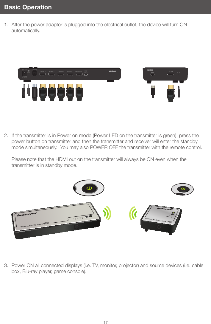
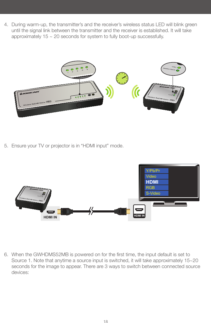
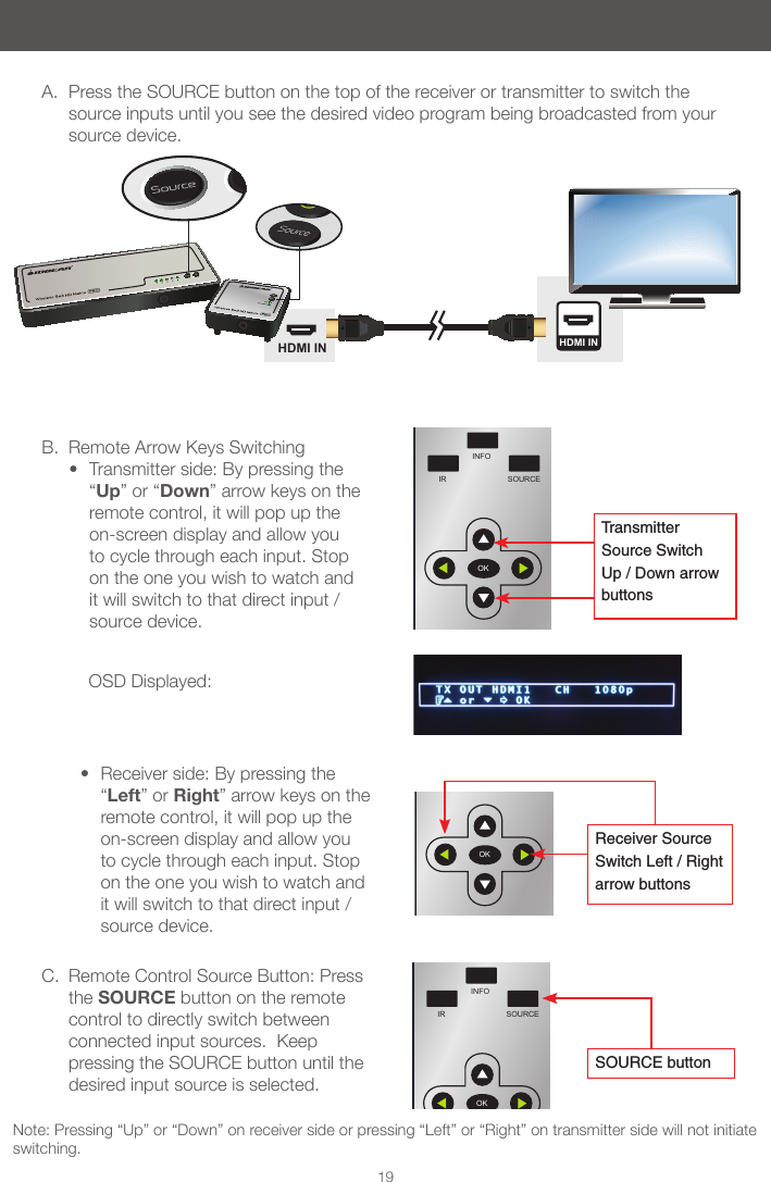
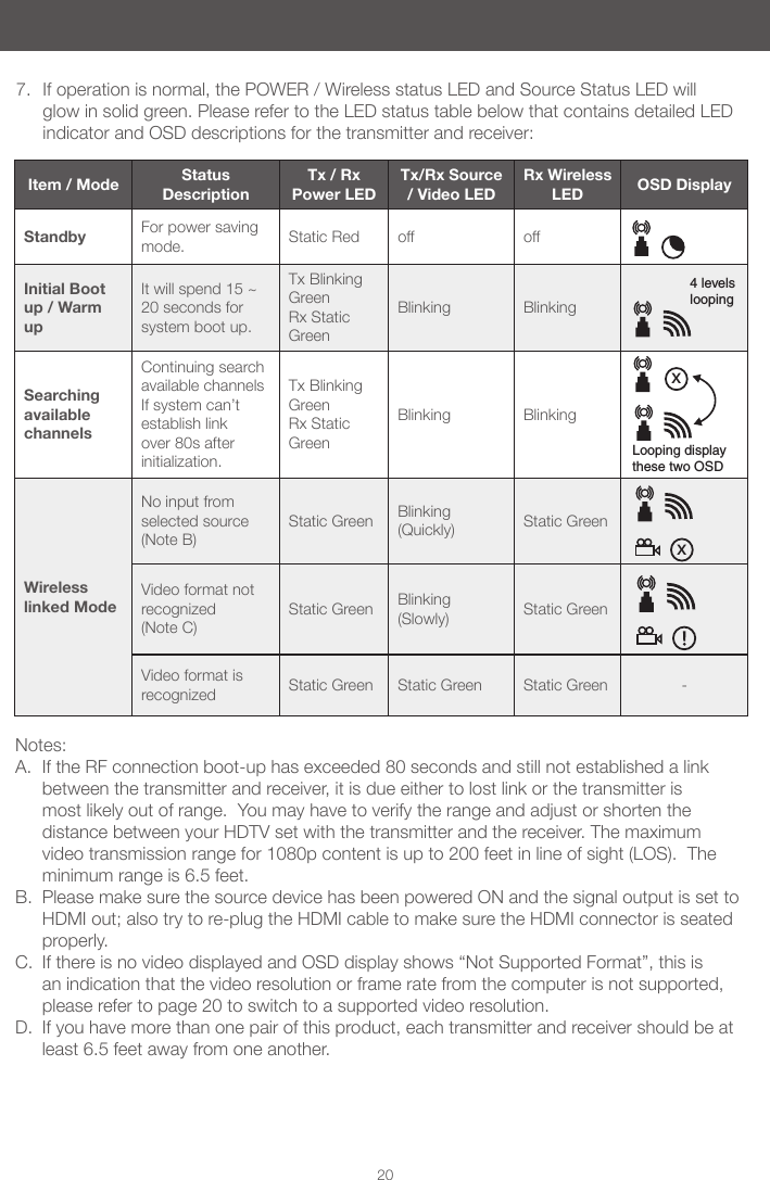
ATEN Technology, Inc., dba IOGEAR Long Range Wireless 5 x 2 HD Matrix Pro -Transmitter GWHDMS52MB T UserMan
Contents
- 1. (GWHDMS52MB - T) UserMan_2014.04.22
- 2. (GWHDMS52MB-T) UserMan Warning
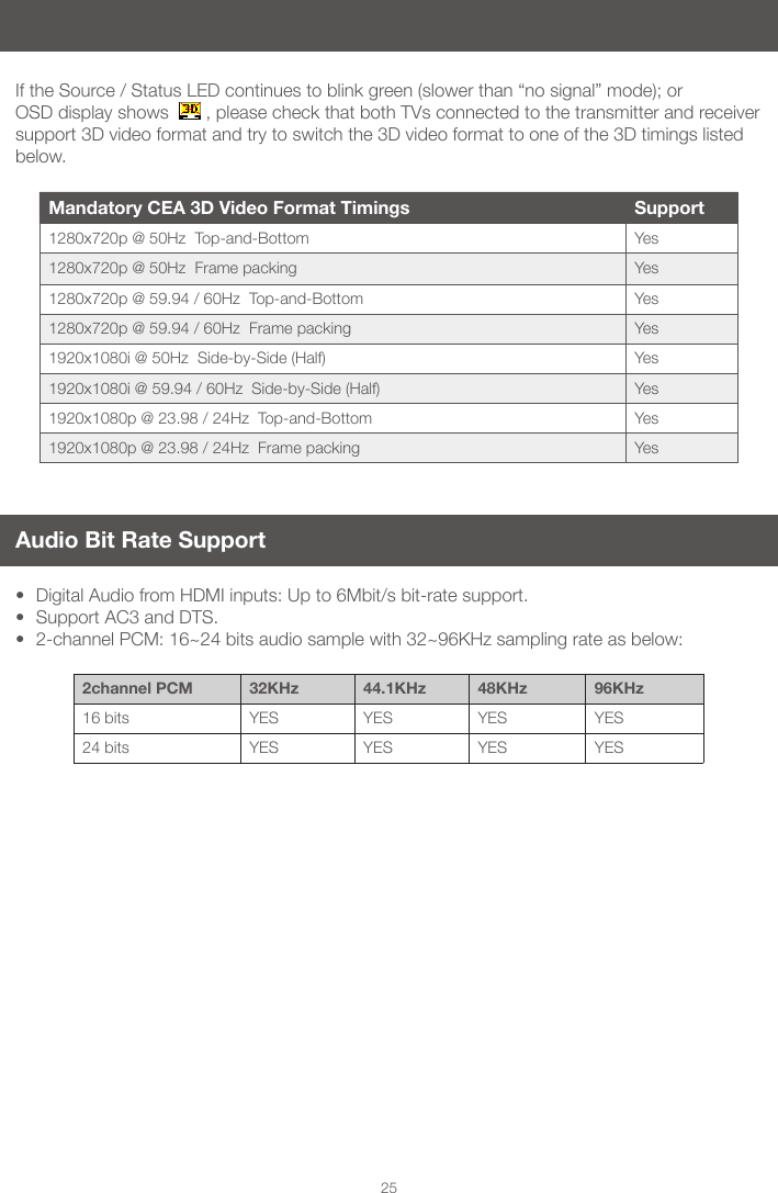
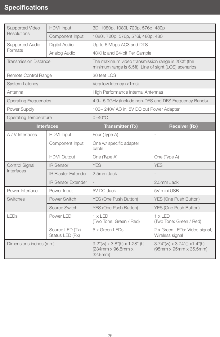
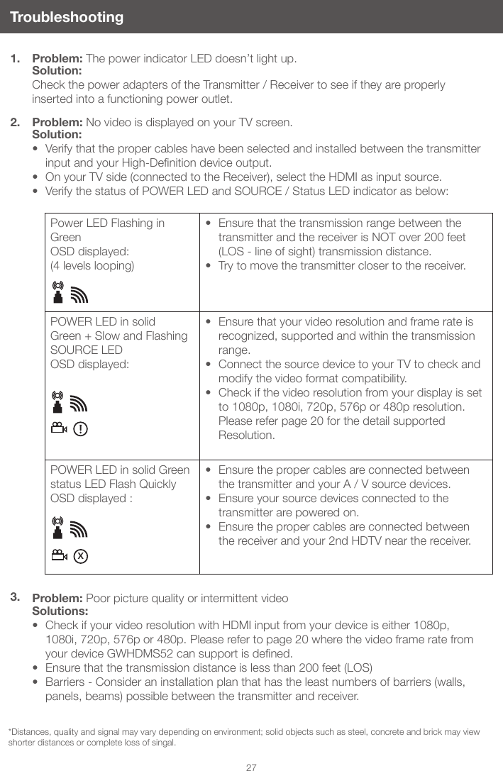
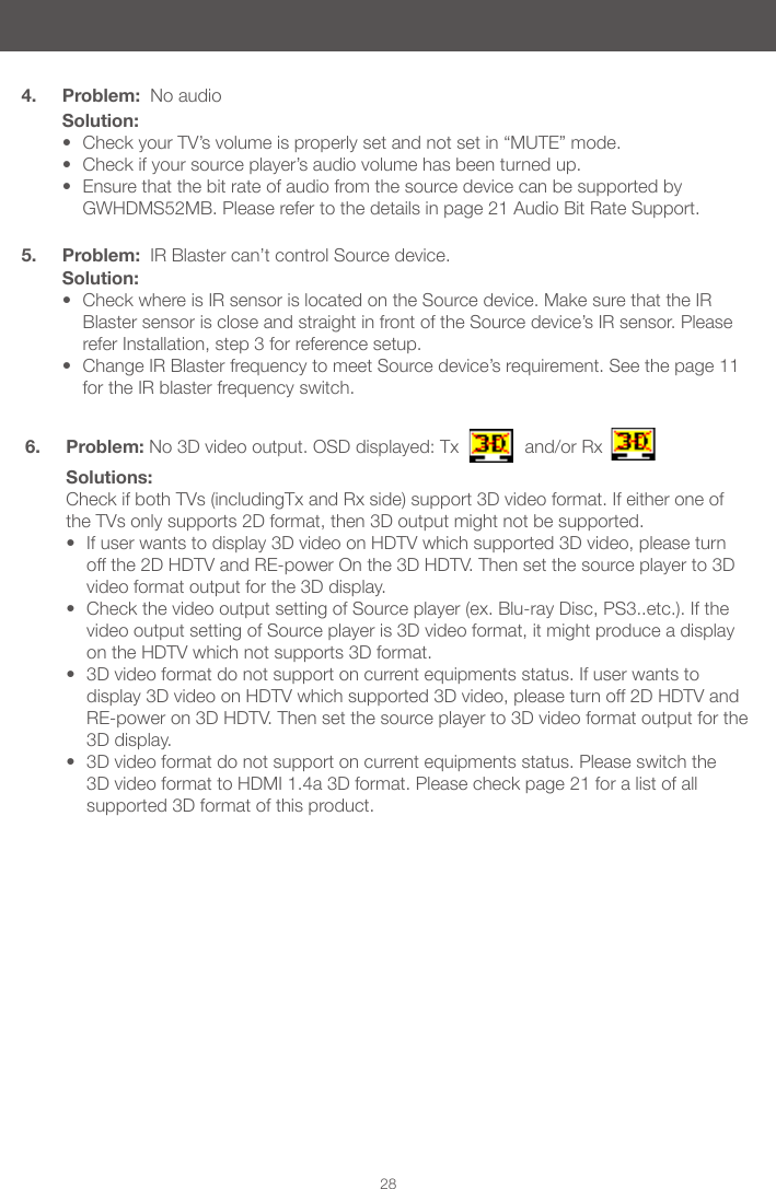
- 3. (GWHDMS52MB-T) UserMan
(GWHDMS52MB-T) UserMan