ATS KRT2 VHF TRANSCEIVER User Manual DE 3000 800100e R5a Manual KRT2
ATS Inc VHF TRANSCEIVER DE 3000 800100e R5a Manual KRT2
UserManual.wiki
>
ATS
>
KRT2 User Manual
Users Manual
Navigation menu
Upload a User Manual
Namespaces
Wiki Guide
HTML
PDF
Info
Views
User Manual
Discussion / Help
Navigation


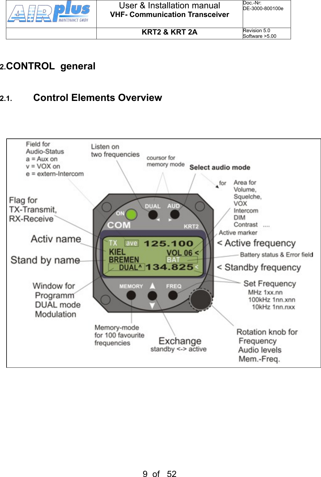
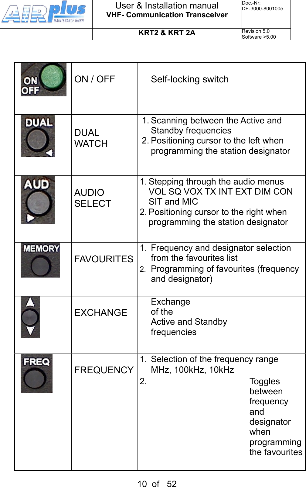
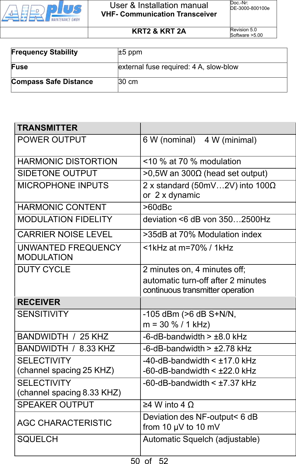
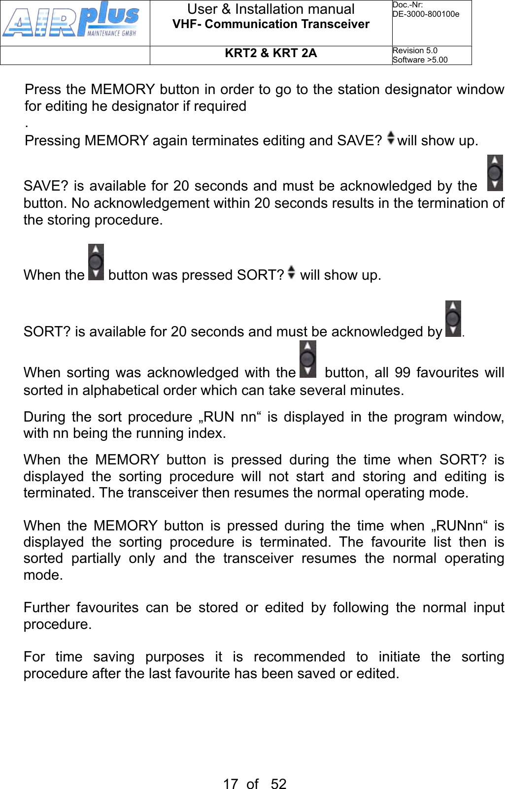
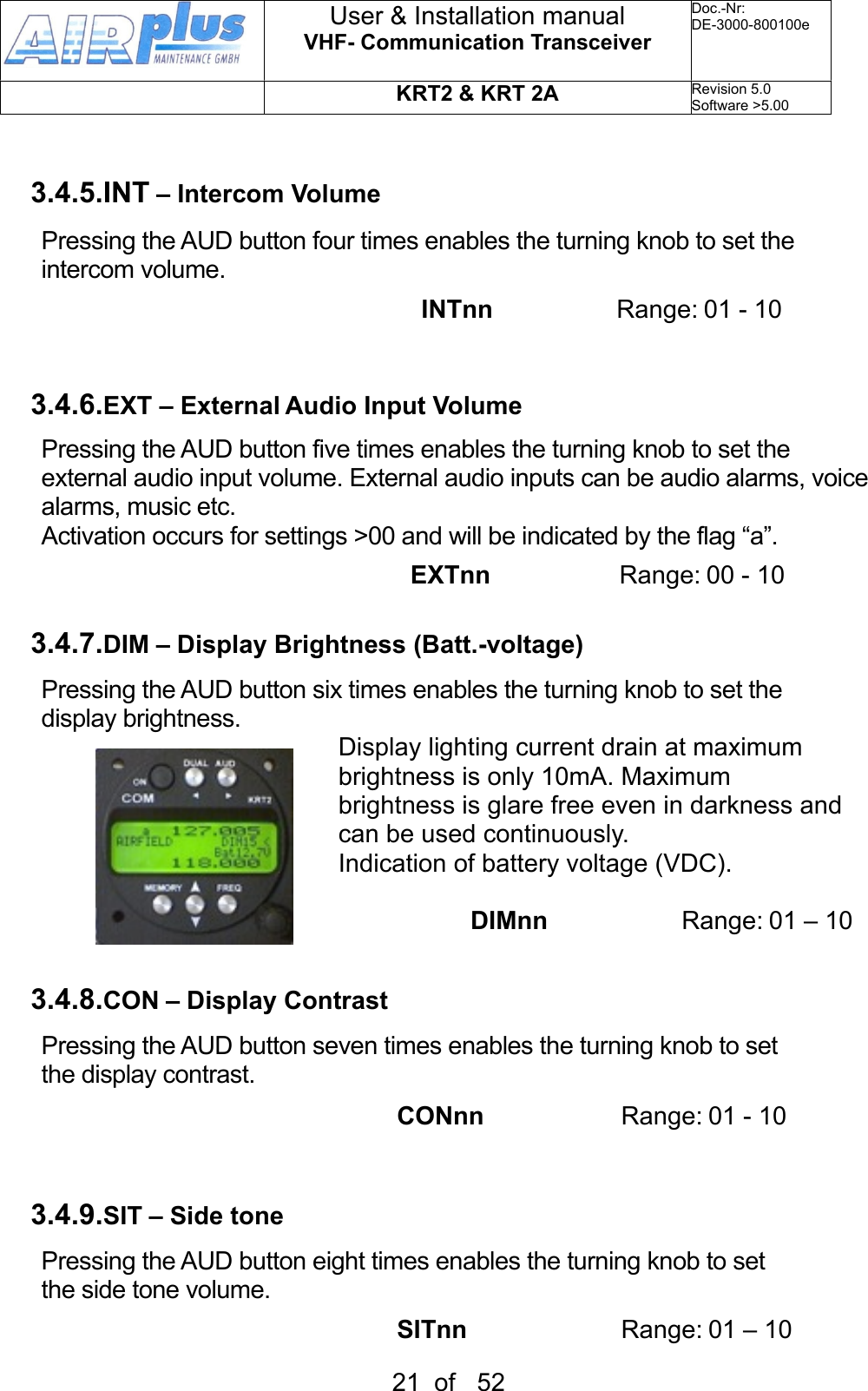
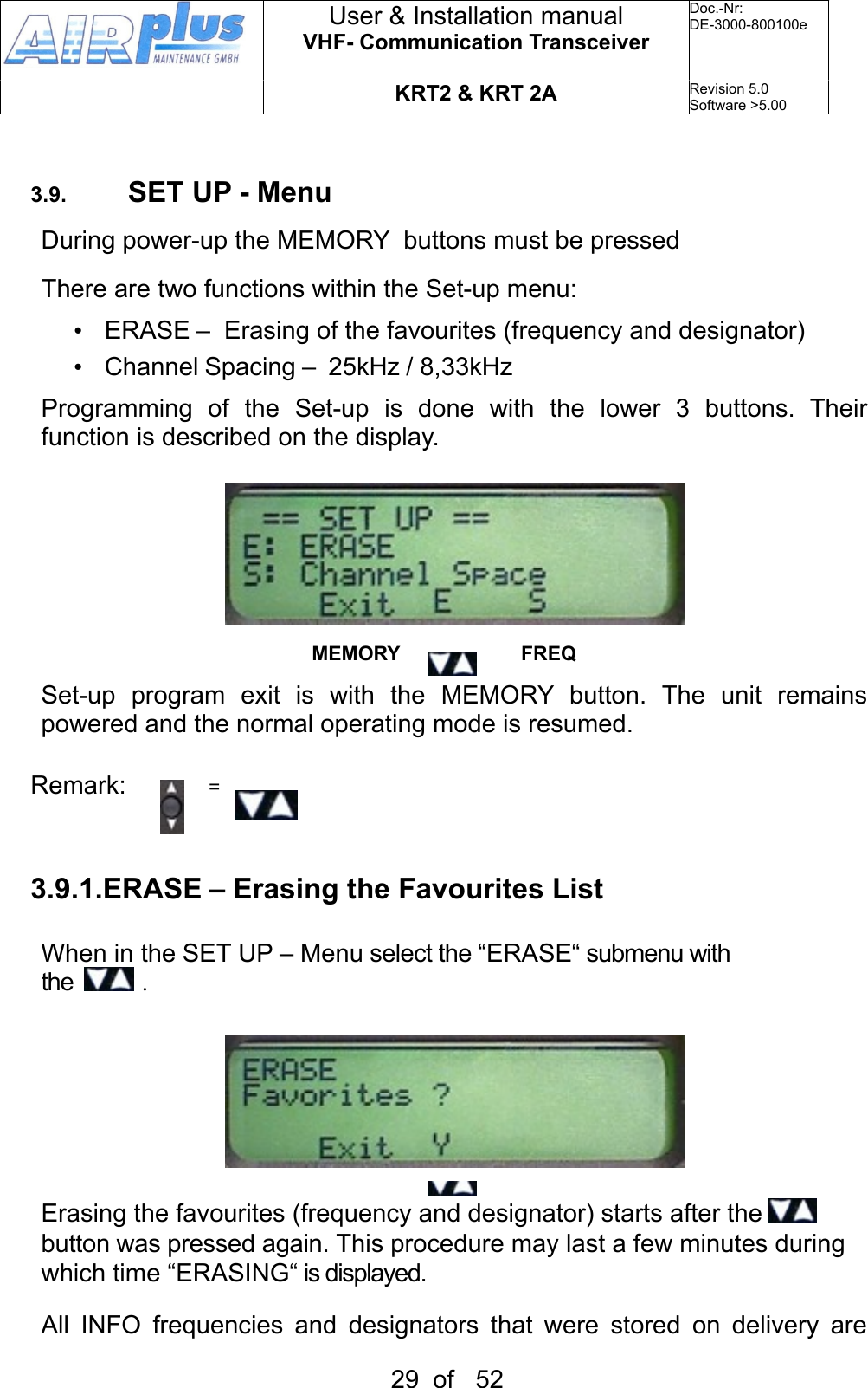
Favourite list index(0-99)When frequency and designator are stored at this index they are displayed125.100 upperActive - frequency134.825 lowerStandby - frequency < The pointer indicates what the turning knob will change 1)VOL SQ VOX…..etc 2)Standby frequency Arrow is positioned in correspondence to the button pressed( AUD or FREQ)BATSupply voltage is low<10,5VBattery low orBattery/Generator faultyUser & Installation manualVHF- Communication TransceiverDoc.-Nr:DE-3000-800100eKRT2 & KRT 2ARevision 5.0Software >5.0012 of 52](https://usermanual.wiki/ATS/KRT2/User-Guide-1822113-Page-12.png)
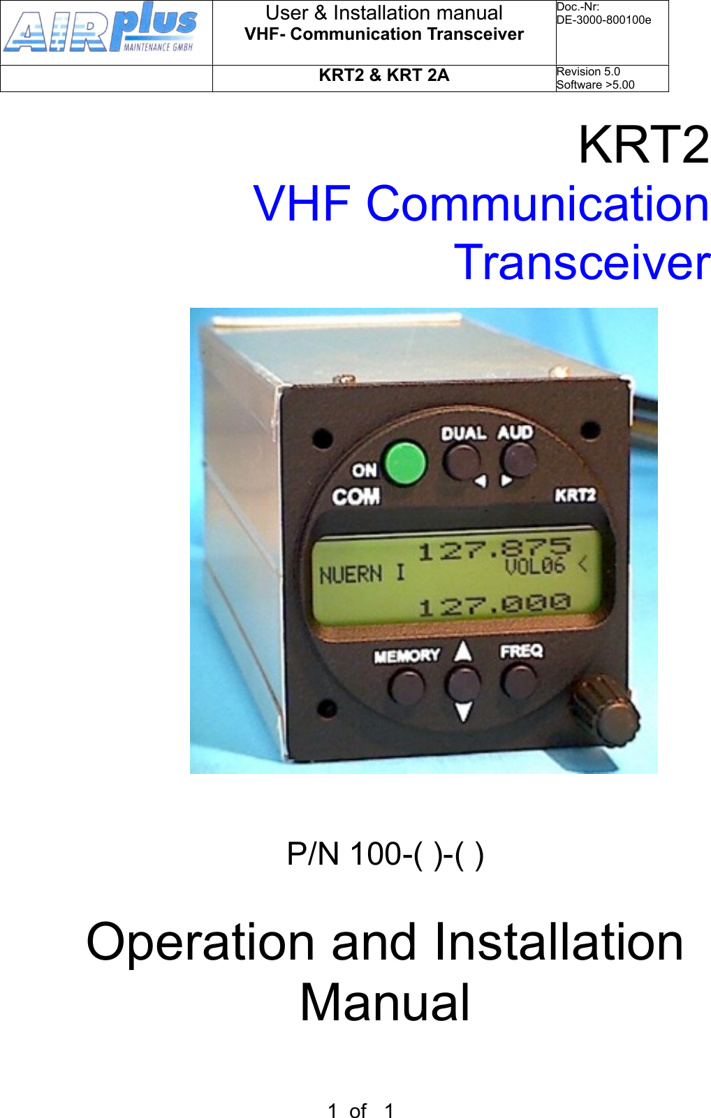
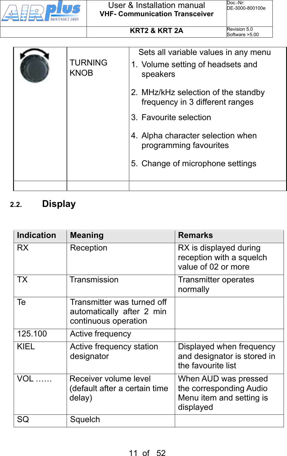
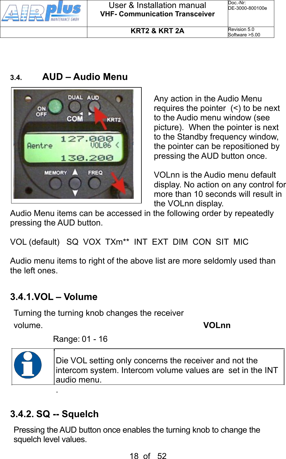
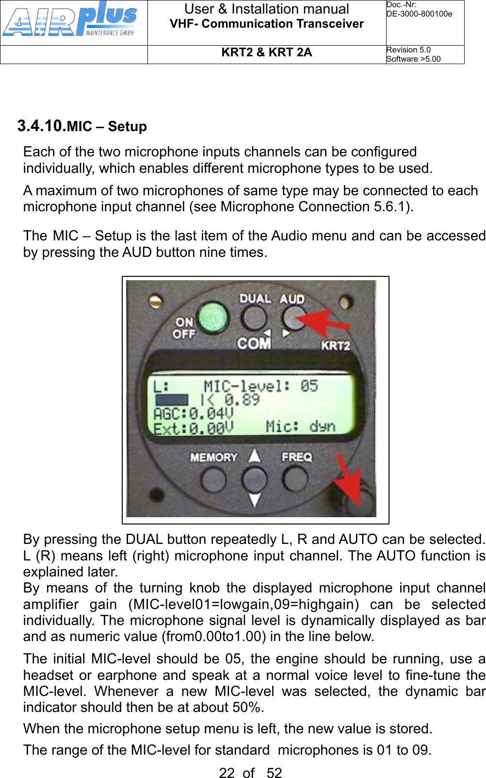
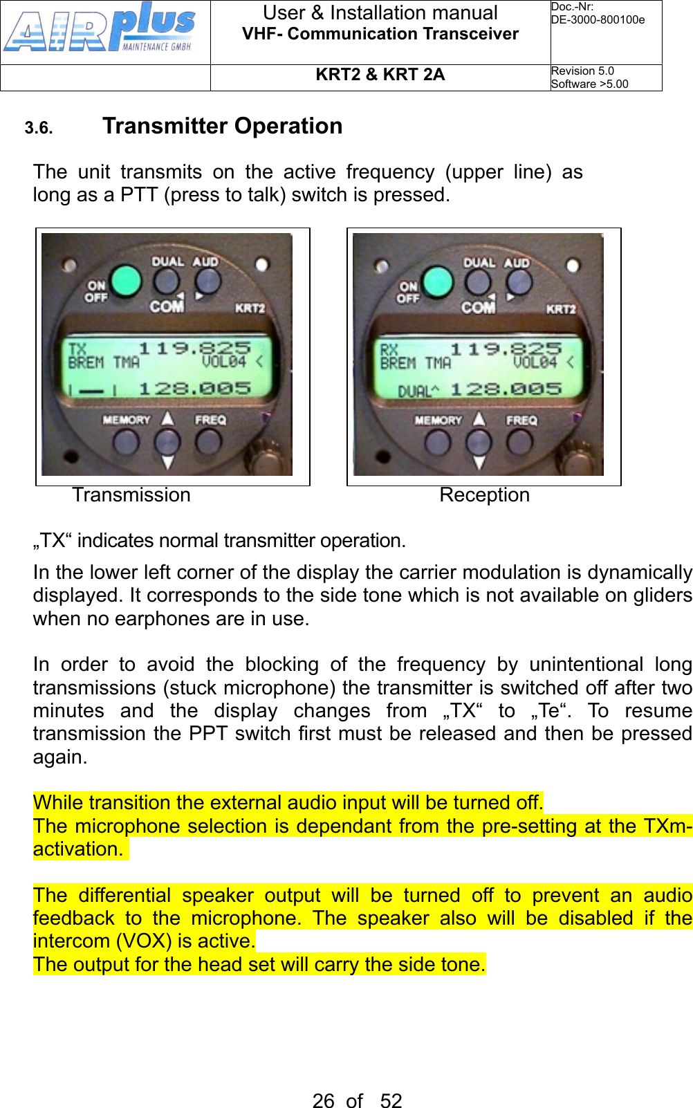
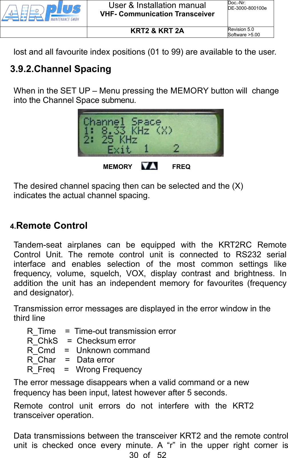
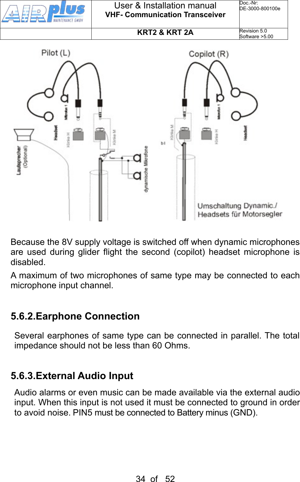
![3.3. Frequency SelectionThere are two different frequency selection methods: • Direct Input• Selection from the favourite list (index 0-99)3.3.1.Direct Frequency SelectionThe Standby-Frequency is set with the tuning knob in 3 different ranges. The selected range is highlighted and can be changed with the FREQ button.Frequency ranges are: 1xx.nnn 1nn.xnn 1nn.nxxPress the FREQ button once or several times until the desired frequency range is highlighted.When the pointer is not next to the Standby Frequency window, it will be repositioned with the first pressing of the FREQ button. Exchanges the Active and Standby frequencies.When the Exchange button was not pressed, the Standby frequency display will return to its normal appearance after 20 seconds.3.3.2. Frequency Selection from the Favourites ListBy pressing and operating the turning knob a specific favourite list position can be accessed [xx] (xx = index 0 … 99). When frequency and station designator have been defined, they will be displayed in the Standby User & Installation manualVHF- Communication TransceiverDoc.-Nr:DE-3000-800100eKRT2 & KRT 2ARevision 5.0Software >5.0015 of 52](https://usermanual.wiki/ATS/KRT2/User-Guide-1822113-Page-15.png)
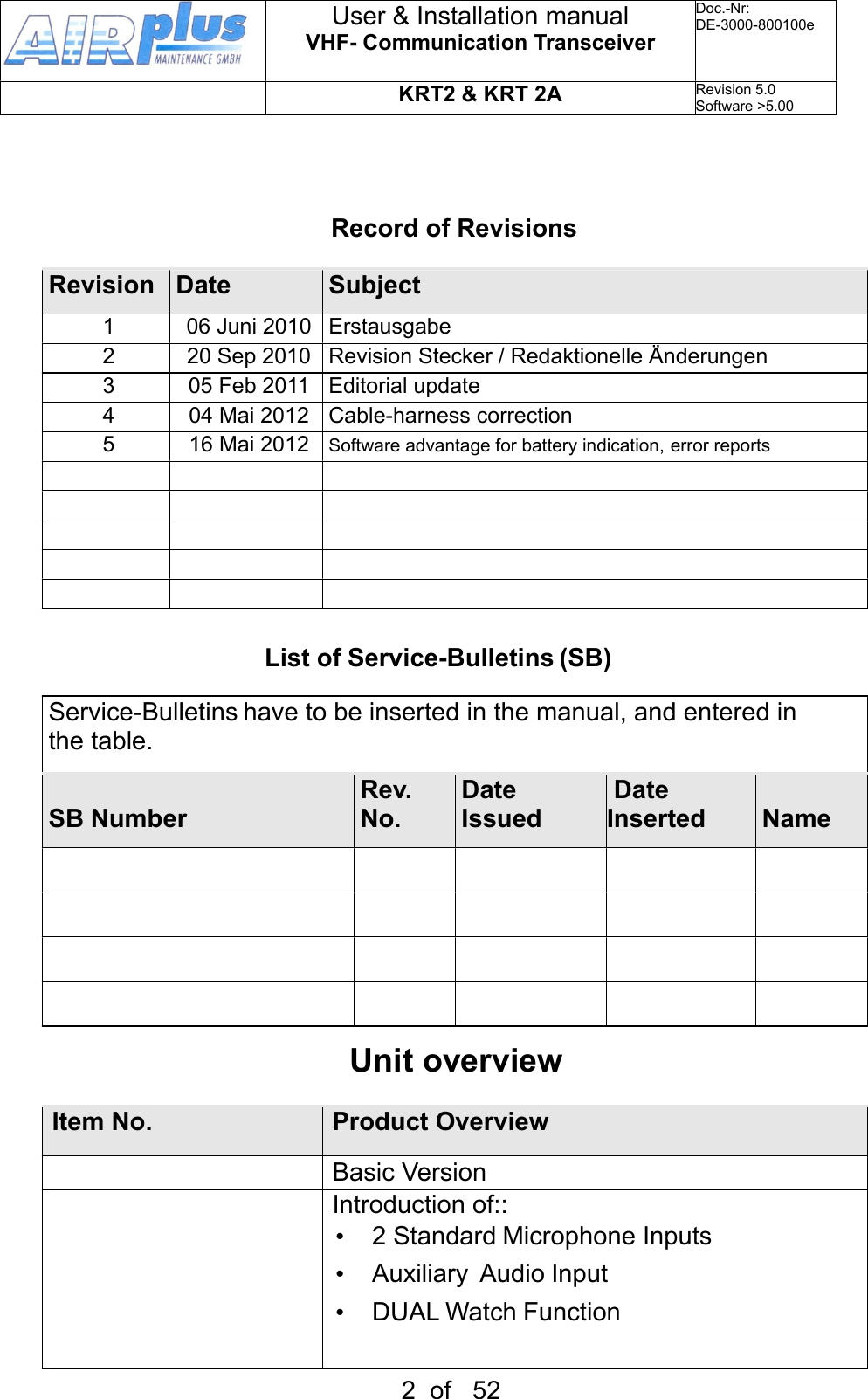
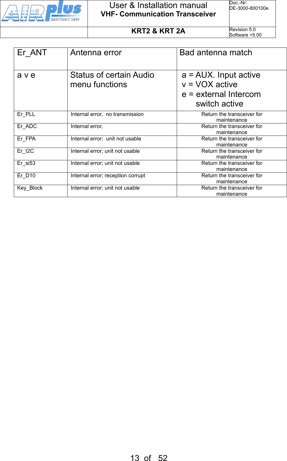
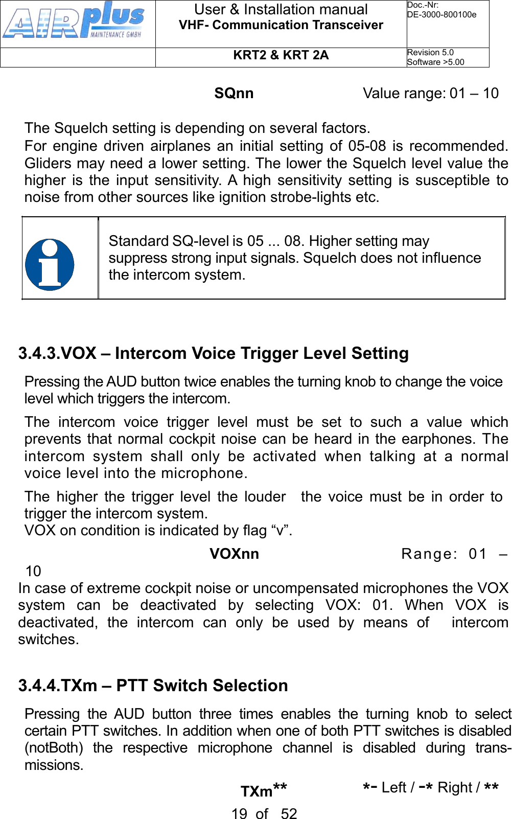
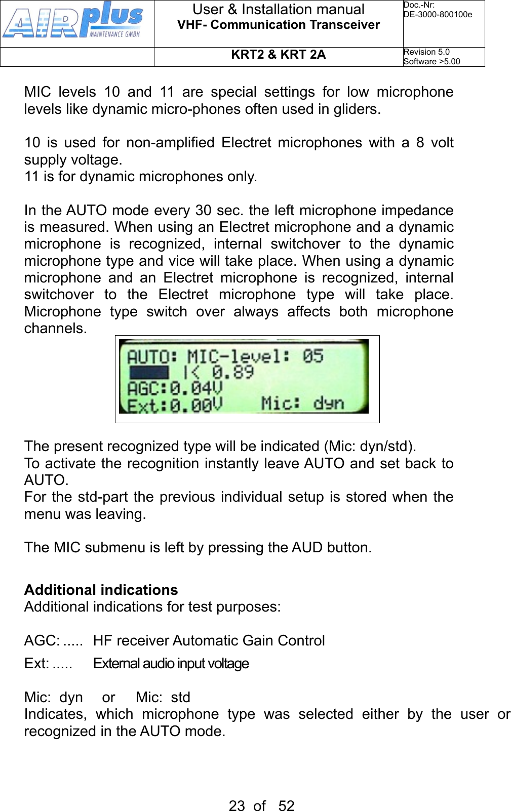
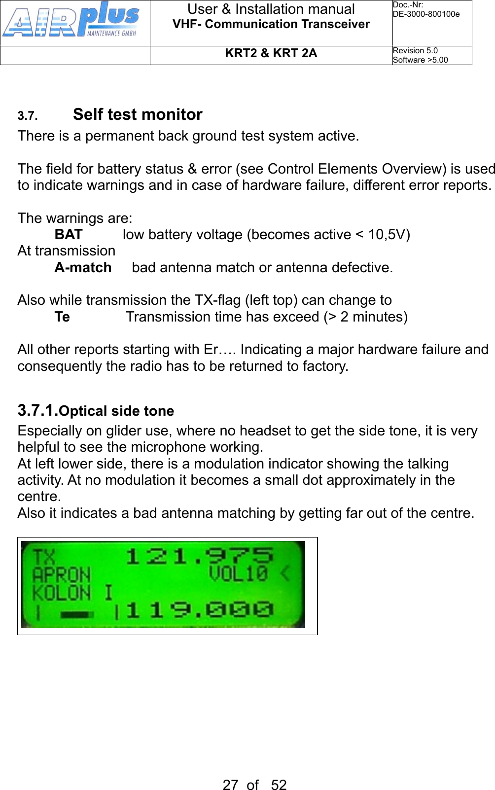
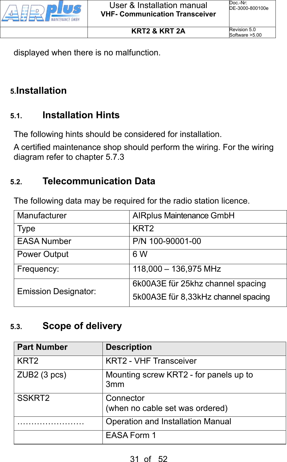
![and station designator windows. The favourite list designators can be sorted in alphabetic order (see 3.3.3). Exchanges the Active and Standby frequencies. The selection procedure can be terminated with either the AUD or FREQ buttons. Without pressing any of these buttons the unit will return to its normal operating mode after 20 seconds.3.3.3. Storing and Editing FavouritesAny displayed Standby Frequency can be given a designator and both can be stored together as favourites in the favourite list. Both, the frequency and designator of a favourite can be edited.First press button and by means oft he turning knob go to the desired favourite list position which may be empty or the favourite to be edited (index [00 …99]).Press the MEMORY button a second time and „–EDIT--„ will show up in the program window. In the designator window a blinking cursor will show up under the most left character. The turning knob selects the desired character.The AUD button positions the curser one character to the right. The DUAL button positions the cursor one character to the left and simultaneously erases this character.The station designator can consist of maximum 8 characters.Press the FREQ button and follow the normal direct input procedure to edit the frequency. User & Installation manualVHF- Communication TransceiverDoc.-Nr:DE-3000-800100eKRT2 & KRT 2ARevision 5.0Software >5.0016 of 52](https://usermanual.wiki/ATS/KRT2/User-Guide-1822113-Page-16.png)
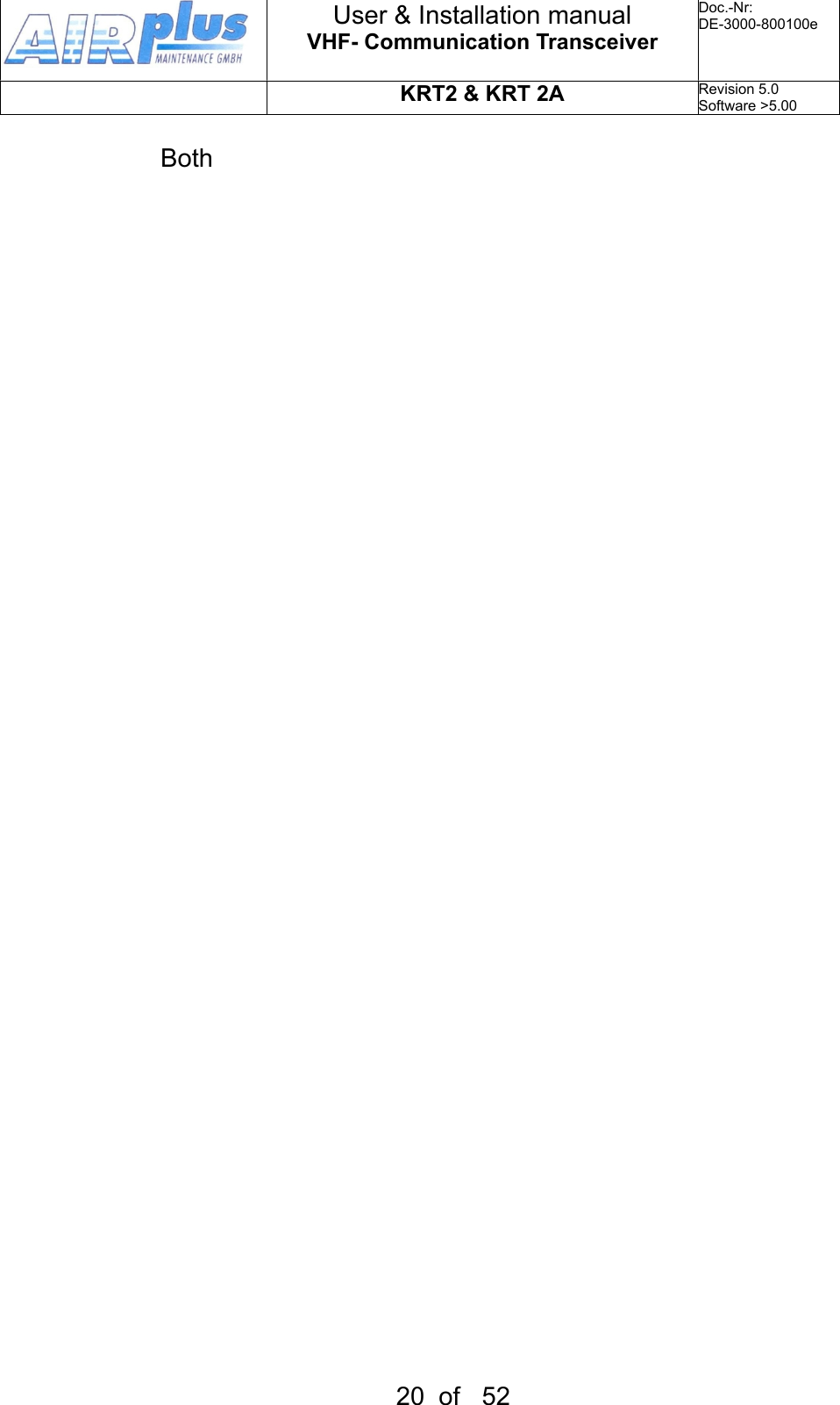
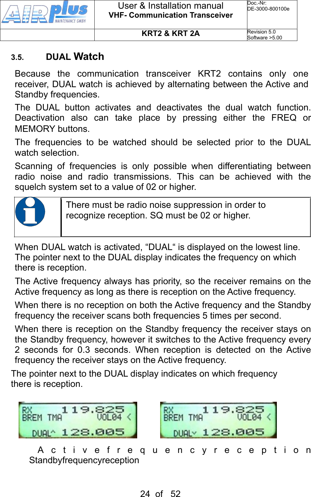
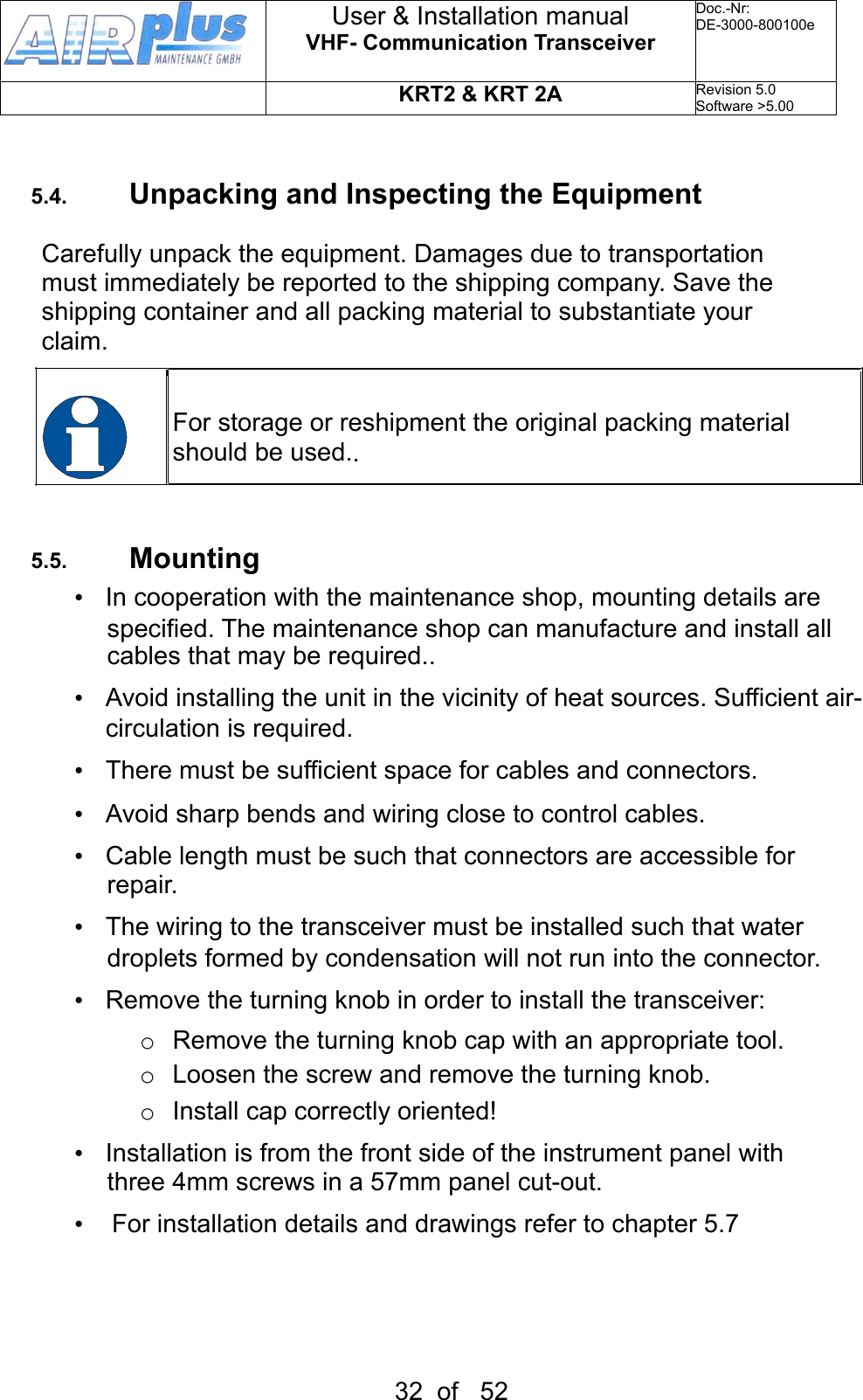
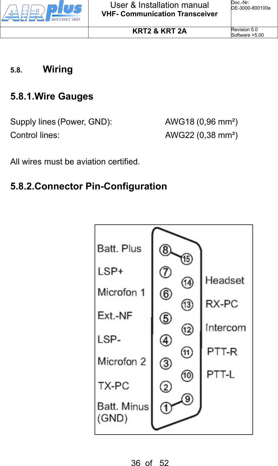


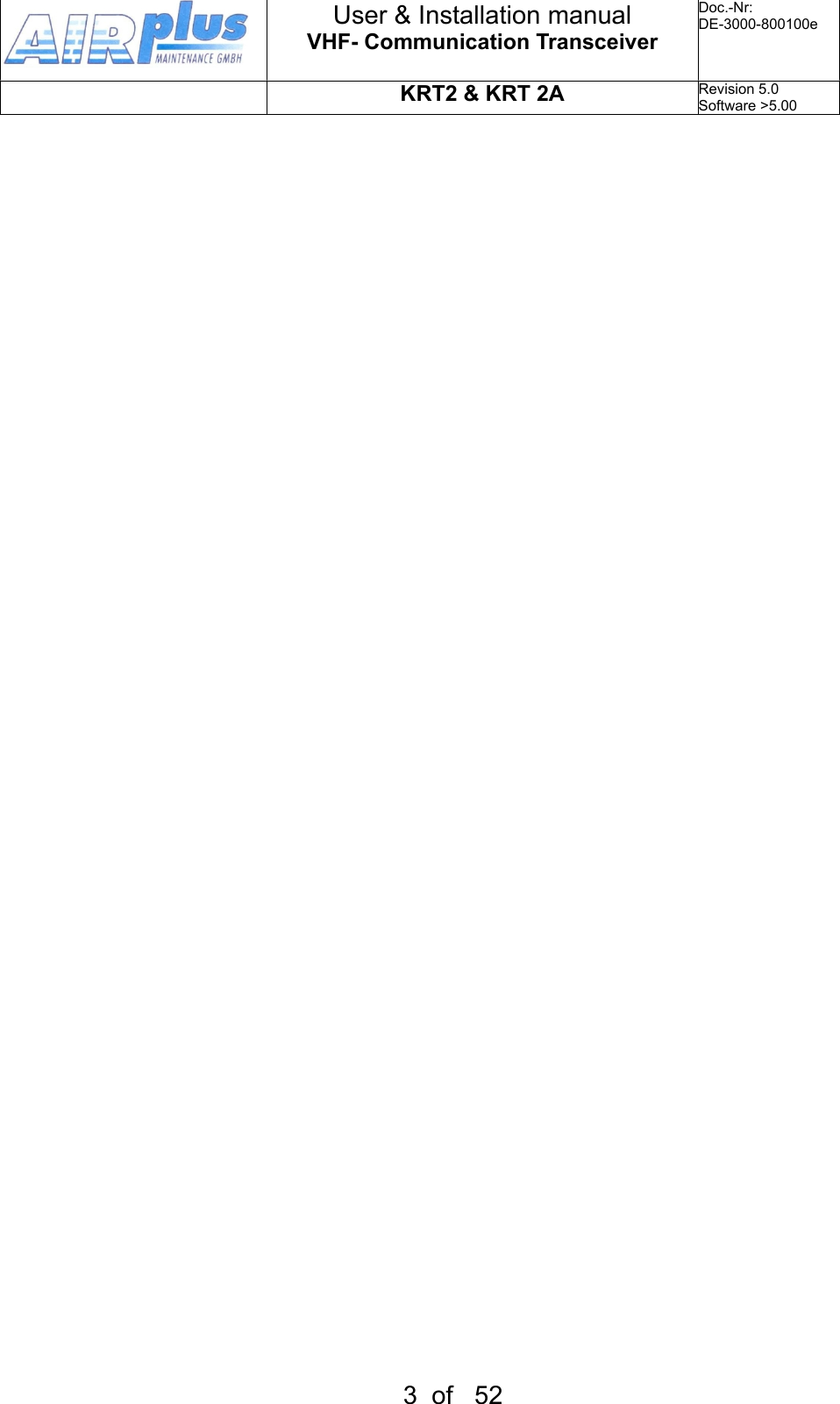
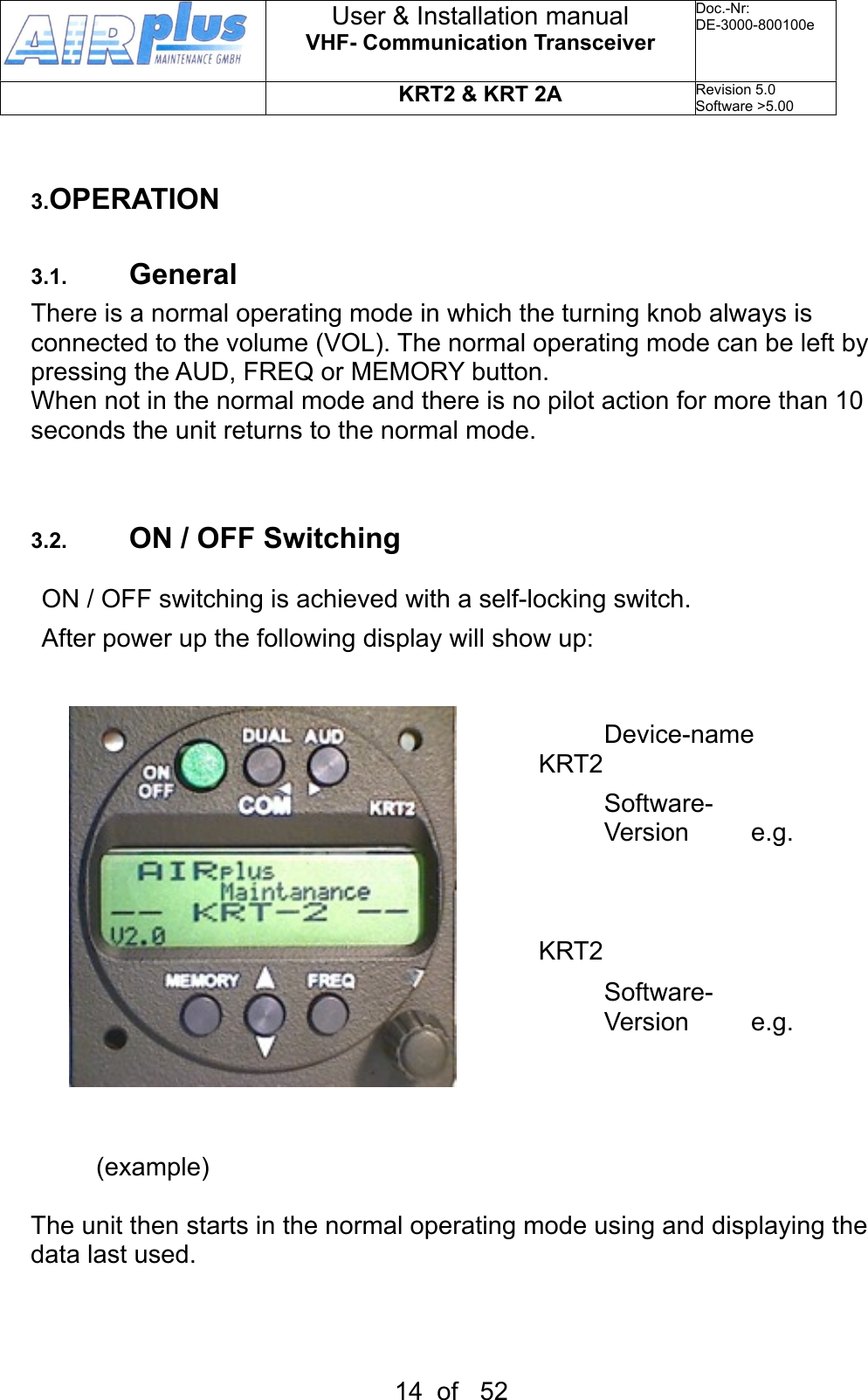
![6.2. Technical DataGENERALCompliance StandardsETSO-2C169a, ED-23B Class 4ED-23B Class CTSO-C169a,Class 6TSO-C169a, Class H1 & H2StandardsEUROCAE ED-23BRTCA DO-160ERTCA DO-178B Software Level DDimensionsHeight: 65 mm Width: 65 mm Depth: 144mm plus rear panel plugs 60mmWeight0.36 kg Mountingpanel mounting, cut-out Ø 57 mmTemperature RangesOperation-20 °C to +55 °CStorage-55 °C to +85 °CMaximum Height35000 ftVibrationDO-160E, Cat. S, Vibration Curve MHumidityRTCA DO-160E, Cat. AShock6 G operation20 G crash safetyRTCA DO-160F ENV. CAT.[C1Z]CAA[SM]XXXXXXZBAAA[YY]M[B3F3]XXAPower Supply9 VDC to 33VDC test @ 12VDC•Transmitter: 2.0 A (typ.)•Receiver: 0.1 A•Illumination 0.02A•Audio Power amp. Up to 1Aemergency operation: 9 VDCPower ConsumptionStandby 1W, Transmit 30 WFrequency Range118.000 .. 136.995 MHz User & Installation manualVHF- Communication TransceiverDoc.-Nr:DE-3000-800100eKRT2 & KRT 2ARevision 5.0Software >5.0049 of 52](https://usermanual.wiki/ATS/KRT2/User-Guide-1822113-Page-49.png)