Abon Tech RF88157101 Radio Frequency Identification (RFID) User Manual RFC157 v1 9 eng
Abon-Tech International Corp. Radio Frequency Identification (RFID) RFC157 v1 9 eng
UserManual.wiki
>
Abon Tech
>
RF88157101 User Manual
User Manual
Navigation menu
Upload a User Manual
Namespaces
Wiki Guide
HTML
PDF
Info
Views
User Manual
Discussion / Help
Navigation
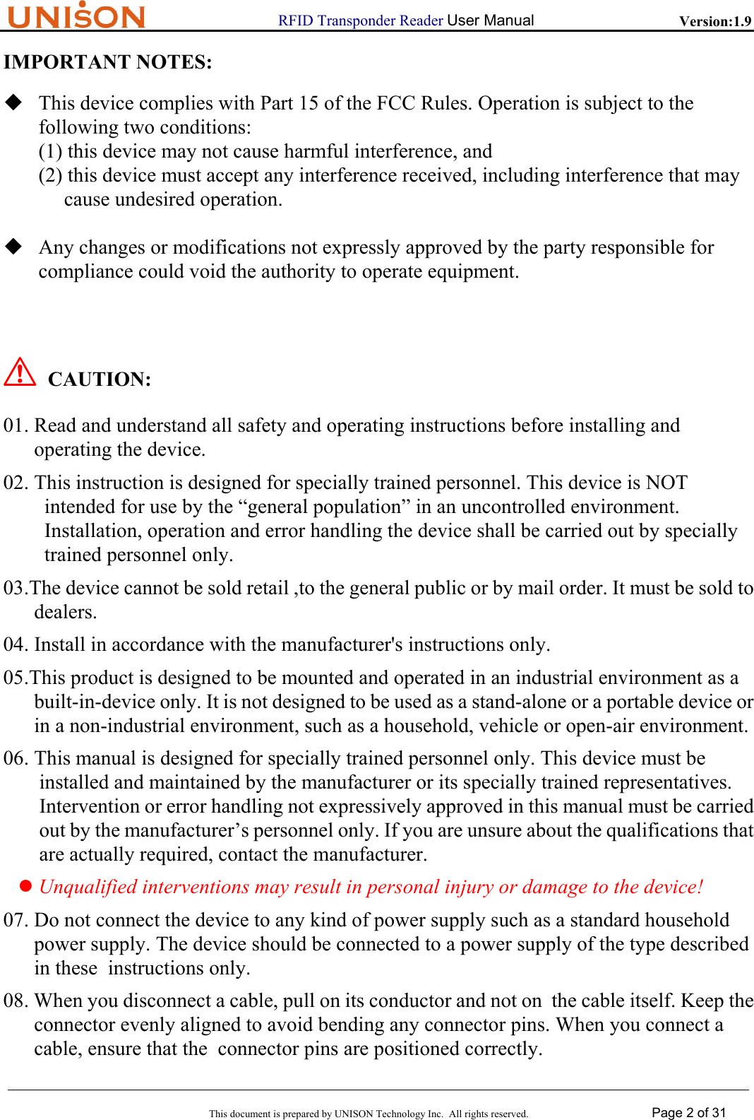
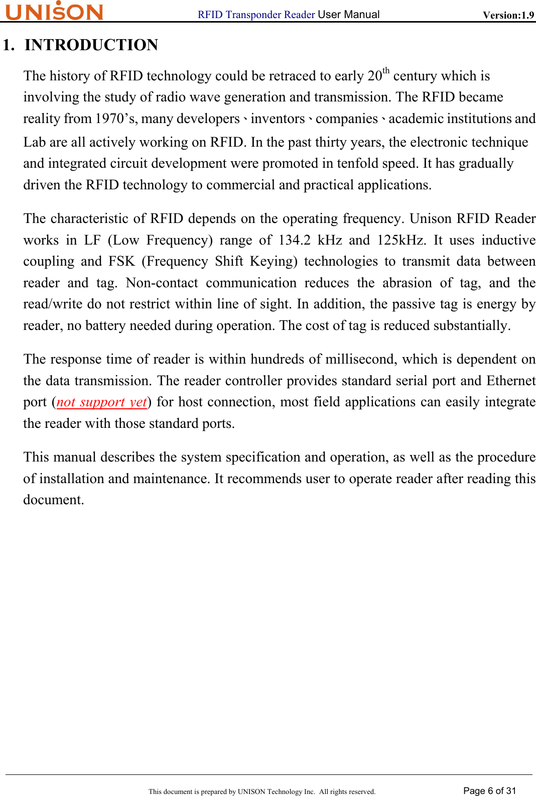
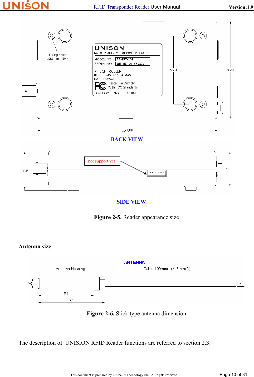
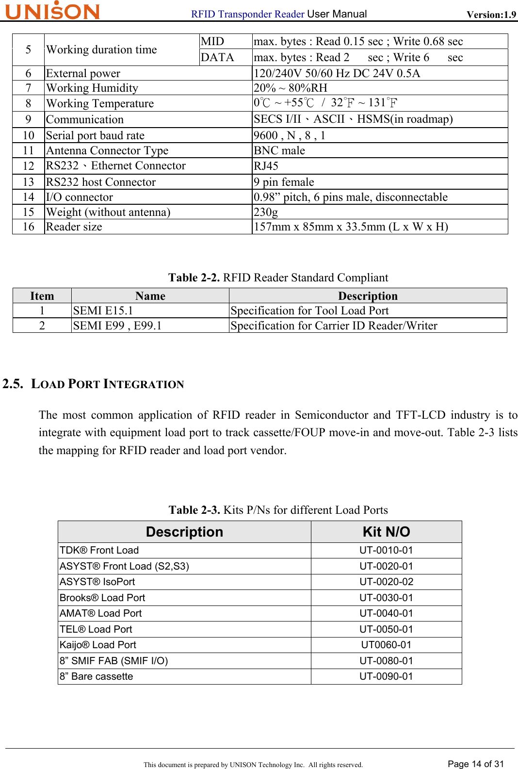
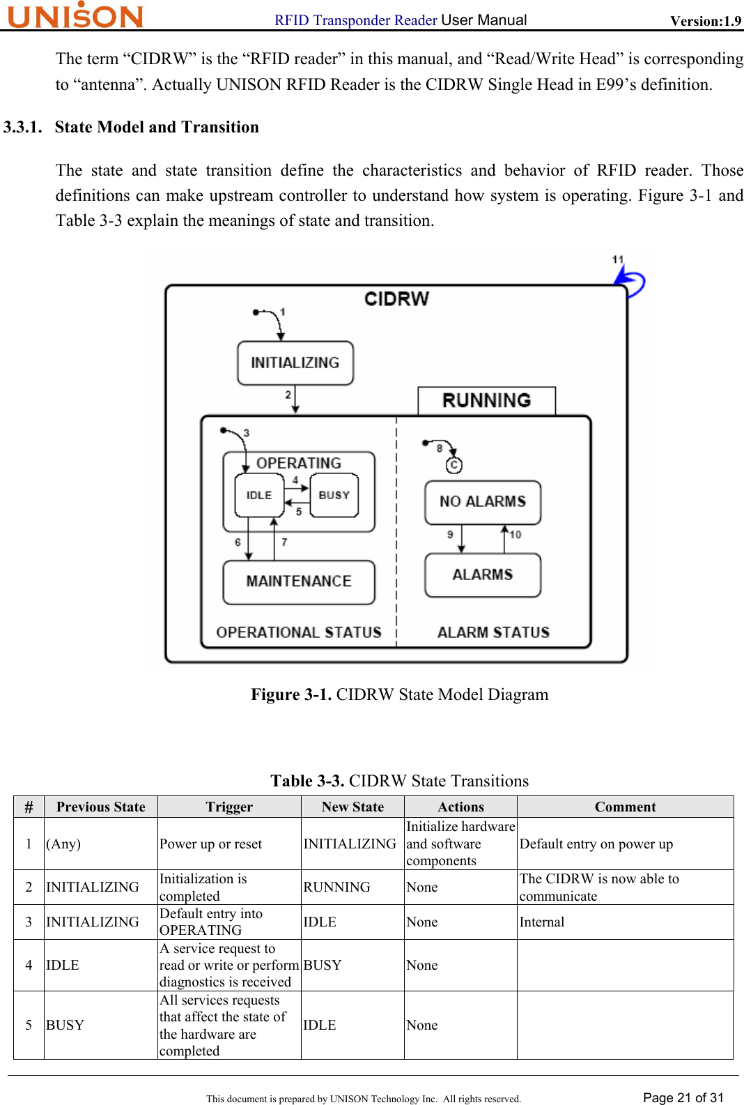
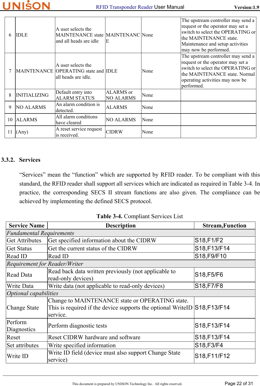
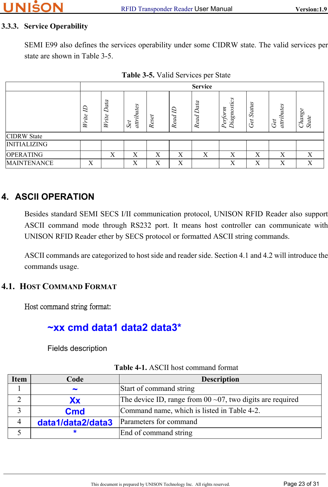
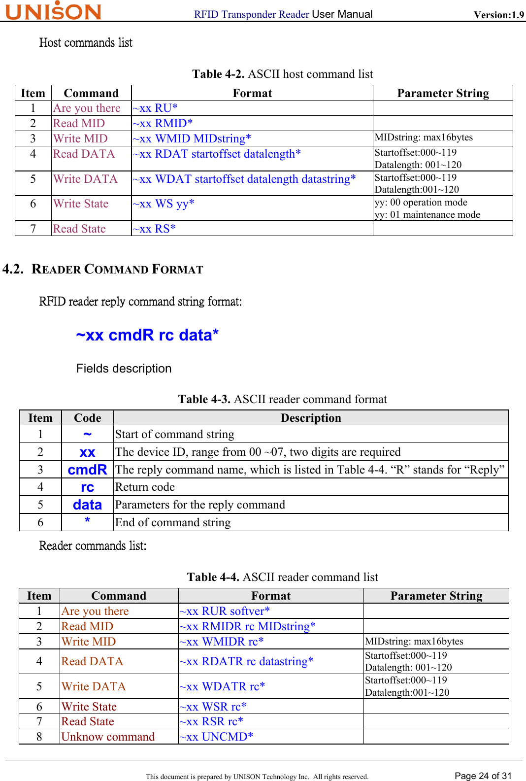
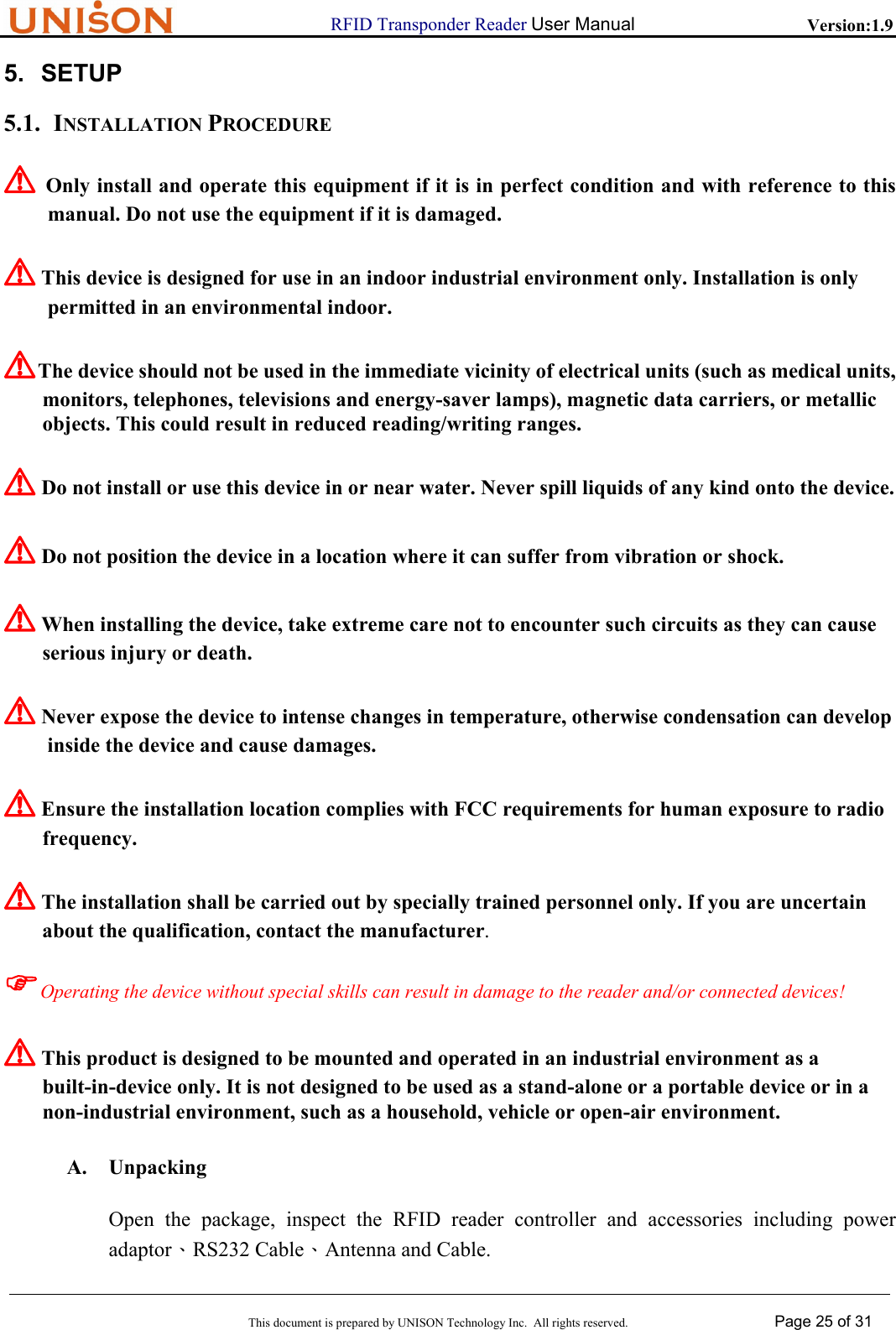
![RFID Transponder Reader User Manual Version:1.9 This document is prepared by UNISON Technology Inc. All rights reserved. Page 16 of 31 1 2 H → R Query system state 3 4 H → R Set system state 5 6 H → R Read data 7 8 H → R Write data 9 10 H → R Read MID 11 12 H → R Write MID 13 14 H → R Change State 73 - H → R Initialize system 18 71 - H ← R Power On status 1 - H ← R unrecognized device ID 3 - H ← R unrecognized stream 5 - H ← R unrecognized function 7 H ← R SECS format error 9 9 - H ← R transaction time out 3.2.2. Message Set Format According to the definition of Stream and Function, the SECS II message format samples are list as follow: 1. S1F1 Are You There Header only 2. S1F2 Are You There reply <L2 < A[20] > //model no. < A[8] > //software version > 3. S18F1 Query System State <L1 <A[00~07]> //Device ID > 4. S18F2 Query System State reply < L3 < A [00~07]> //DeviceID < A [XX] > //Return code <L4 < A [XX] > //PM information < A [1~8] > //Alarm status < A [XXXX] > //Operation state < A [XXXX] > //Head status > >](https://usermanual.wiki/Abon-Tech/RF88157101/User-Guide-532447-Page-16.png)
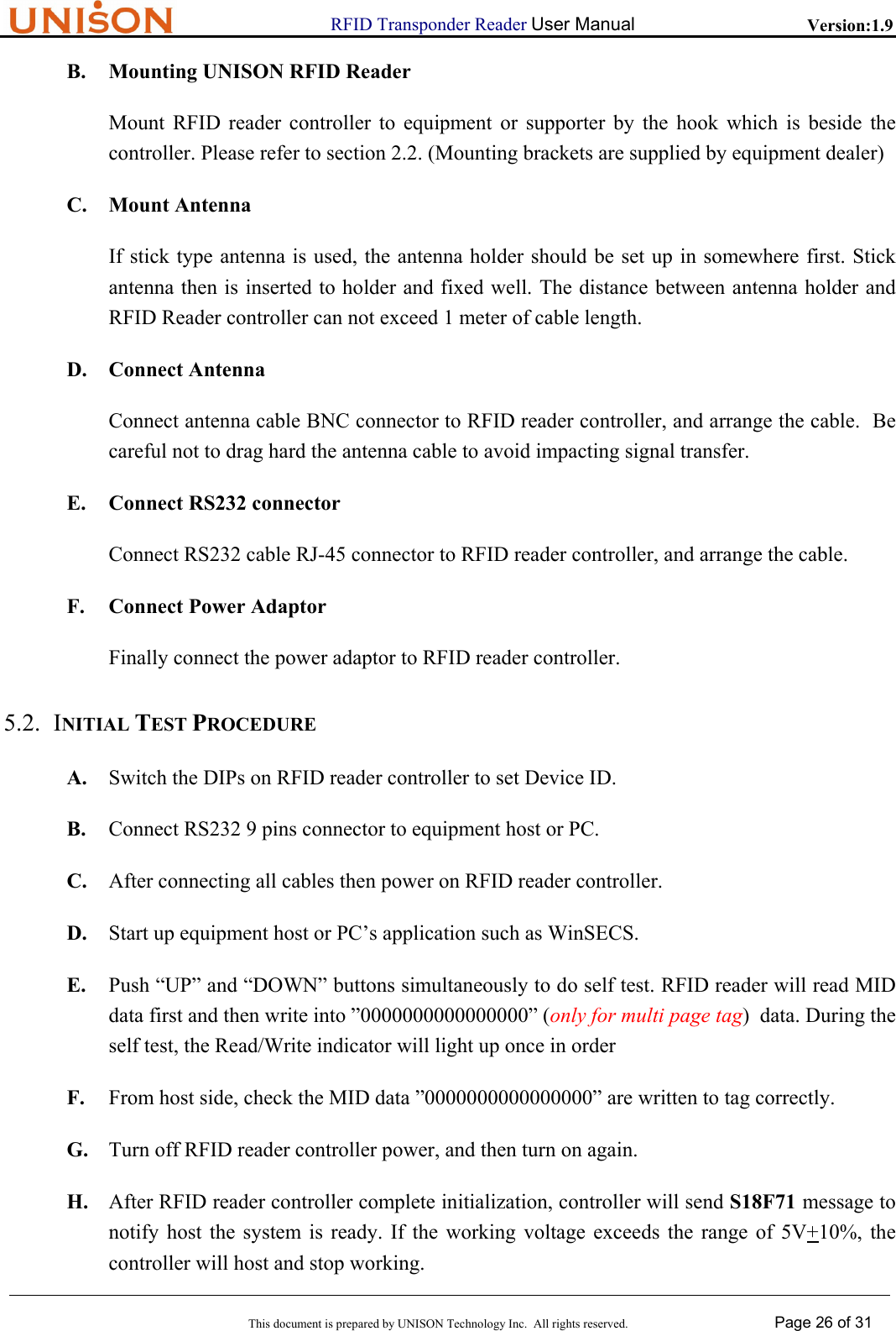
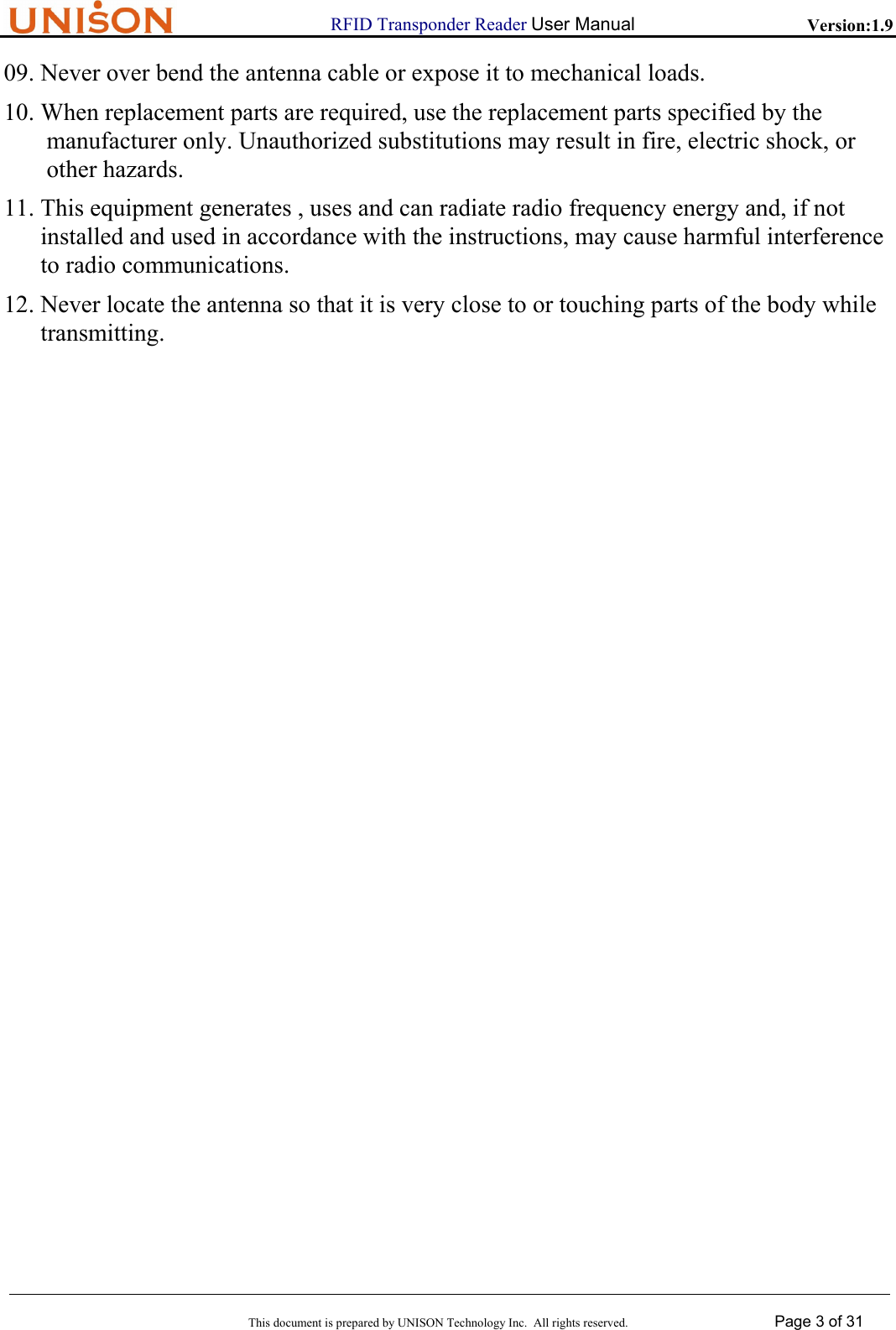
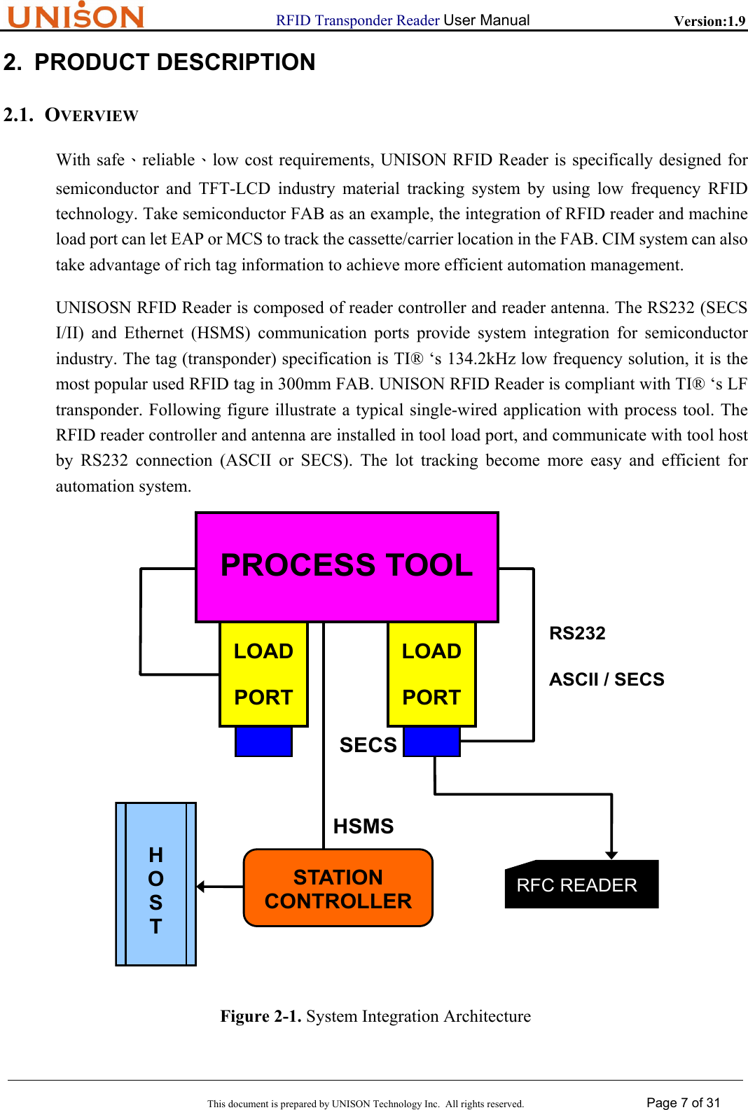
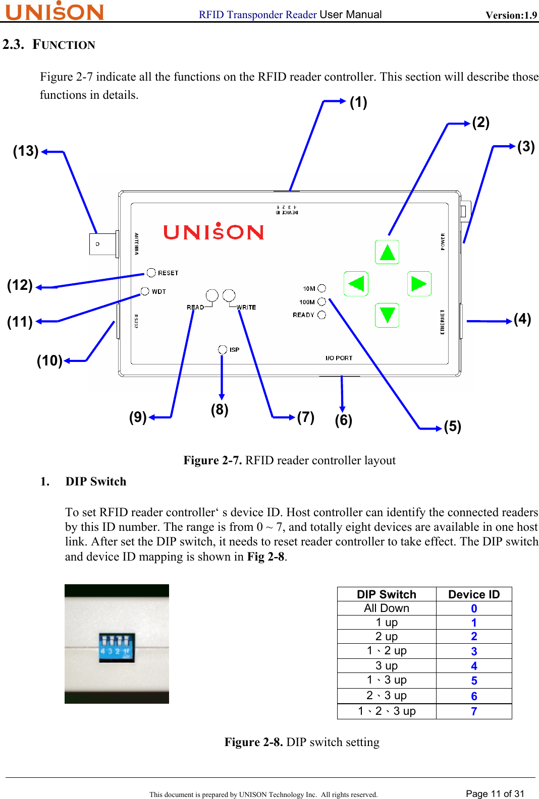
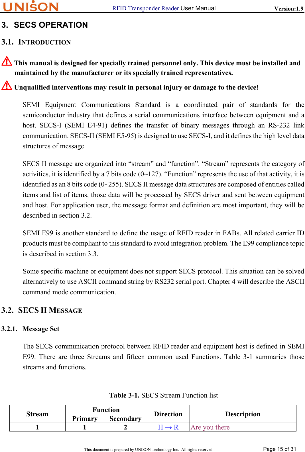
![RFID Transponder Reader User Manual Version:1.9 This document is prepared by UNISON Technology Inc. All rights reserved. Page 17 of 31 5. S18F3 Set System State <L2 <A[00~07]> //Device ID <A[00~01]> //setting value > 6. S18F4 Set System State reply < L3 < A [0~7]> //DeviceID < A [XX] > //Return code <L4 < A [XX] > //PM information < A [1~8] > //Alarm status < A [XXXX] > //Operation state < A [XXXX] > //Head status > > 7. S18F5 Read Data <L3 < A[00~07] > // DeviceID < A [0~119] > // Start offset address < A [ReadNo.] > // Number of bytes to read > 8. S18F6 Read Data reply < L4 < A[00~07] > //Device ID < A[XX] > //Return code < A [Data string] > //Return Data string <L4 < A [XX] > //PM information < A [1~8] > //Alarm status < A [XXXX] > //Operation state < A [XXXX] > //Head status > > 9. S18F7 Write Data < L4 < A [00~07] > //DeviceID < A [0~119] > //Start offset address < A [1~120] > //bytes to write < A [String to write] > //Data to write > 10. S18F8 Write Data reply < L3](https://usermanual.wiki/Abon-Tech/RF88157101/User-Guide-532447-Page-17.png)
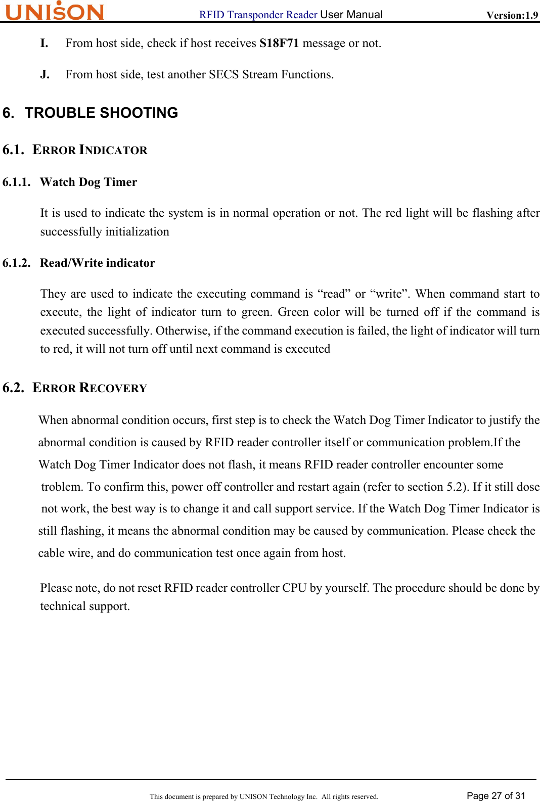
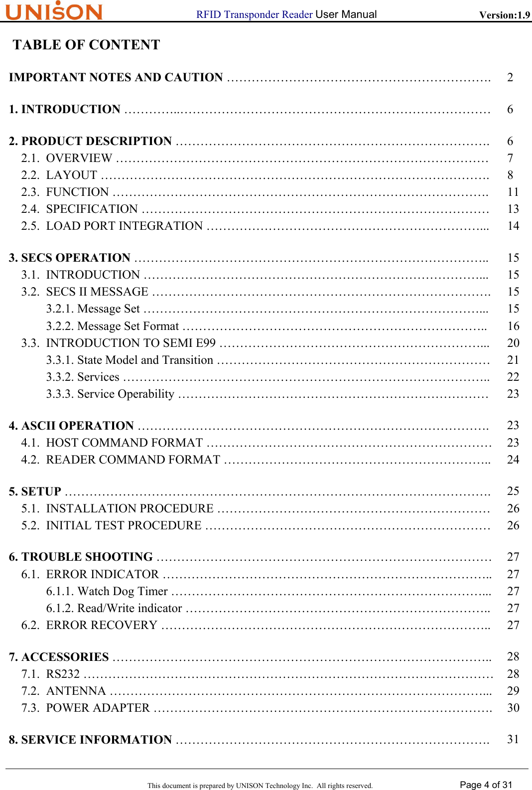
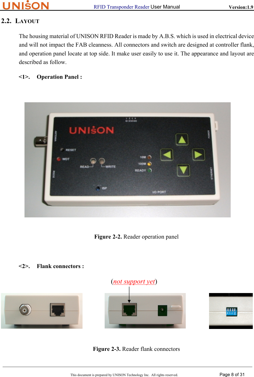
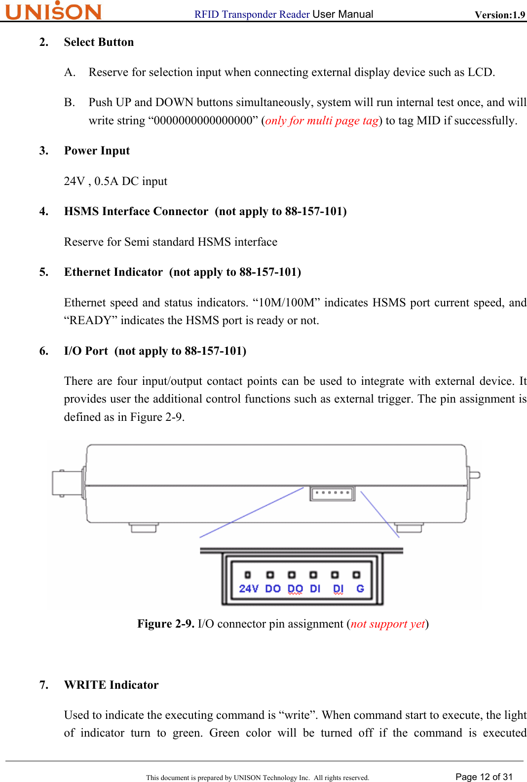
![RFID Transponder Reader User Manual Version:1.9 This document is prepared by UNISON Technology Inc. All rights reserved. Page 18 of 31 < A [00~07] > //DeviceID < A [XX] > //Return Code <L4 < A [XX] > //PM information < A [1~8] > //Alarm status < A [XXXX] > //Operation state < A [XXXX] > //Head status > > 11. S18F9 Read MID < A [00~07] > //DeviceID 12. S18F10 Read MID reply < L3 < A [00~07] > //DeviceID < A [XX] > //Return code < A [MID string]> //Return MID, max 16 bytes <L4 < A [XX] > //PM information < A [1~8] > //Alarm status < A [XXXX] > //Operation state < A [XXXX] > //Head status > > 13. S18F11 Write MID < L3 < A [00~07]> //DeviceID < A [String to write] > //String to write <L4 < A [XX] > < A [1~8] > < A [XXXX] > < A [XXXX] > > > 14. S18F12 Write MID reply < L3 < A [00~07] > //DeviceID < A [XX] > //Return Code <L4 < A [XX] > //PM information < A [1~8] > //Alarm status < A [XXXX] > //Operation state < A [XXXX] > //Head status > > 15. S18F13 Change State <L2 <A[00~07]> //Device ID](https://usermanual.wiki/Abon-Tech/RF88157101/User-Guide-532447-Page-18.png)
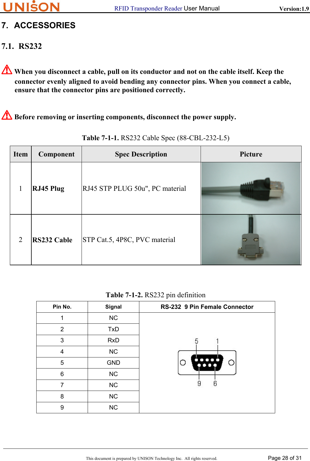
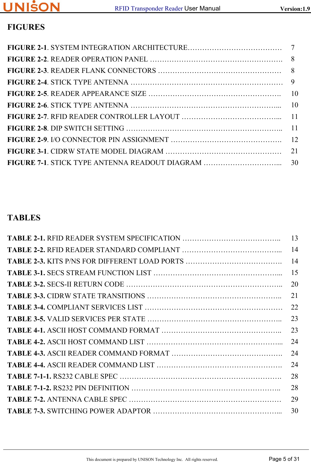
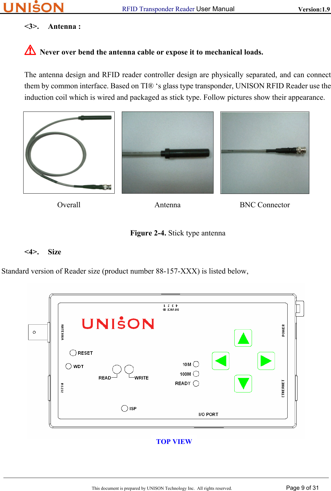
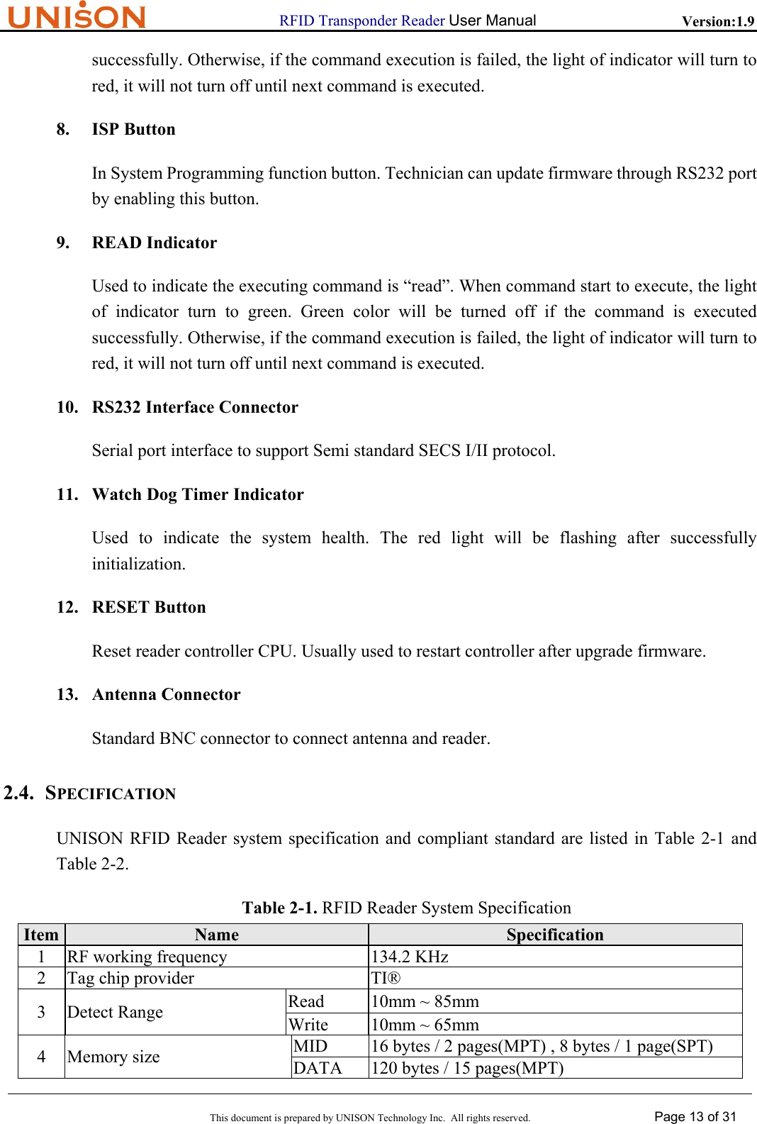
![RFID Transponder Reader User Manual Version:1.9 This document is prepared by UNISON Technology Inc. All rights reserved. Page 19 of 31 <A[00~01]> //Operation State : // ”00” operating // ”01” maintenance > 16. S18F14 Change State reply < L3 < A [00~07]> //DeviceID < A [XX] > //Return code <L4 < A [XX] > //PM information < A [1~8] > //Alarm status < A [XXXX] > //Operation state : // ”IDLE” operating // ”MANT” maintenance < A [XXXX] > //Head status > > 17. S18F71 Power On status <L4 < A[00~07] > //Device ID < A[XX] > //Return code < A[XX] > //EventReport ID // 01: pod arrive // 02: pod remove // 05: power on <L2 //only in “pod arrive” event < ‘AutoReadData’ > //fixed string < A [MID string] > //Return MID, max 16 bytes > > 18. S18F73 Initialize system Header only 19. S9F1 Unrecognized Device ID <L2 < A [00~07]> < A ‘UD’ > //unrecognized DeviceID > 20. S9F3 Unrecognized Stream <L2 < A [00~07]> < A ‘US’ > //unrecognized Stream > 21. S9F5 Unrecognized Function <L2](https://usermanual.wiki/Abon-Tech/RF88157101/User-Guide-532447-Page-19.png)
![RFID Transponder Reader User Manual Version:1.9 This document is prepared by UNISON Technology Inc. All rights reserved. Page 20 of 31 < A [00~07]> < A ‘UF’ > //unrecognized function > 22. S9F7 SECS format error <L2 < A [00~07]> < A ‘FE’ > //SECS format error > 23. S9F9 Transaction Time Out <L2 < A [00~07]> < A ‘T2’ > //Transaction Time Out > The return codes of UNISON RFID Reader in SECS II message string are summarized in Table 3-2. Application program can acquire those codes to process event routine. Table 3-2. SECS-II Return Code Item Name Description 1 NO Normal Operation 2 CE Communication Error,no transponder appeared or transponder does not response3 24 CRC check error for transponder response 4 TE Timing Error 5 FE SECS message item number does not match. 6 05 Data length not correct in item(offset or read/write bytes) 7 04 Written MID data is too long (over16 bytes) 8 19 SECS message format are not correct from host 9 SM System state Mismatch,can not read/write (E99) 10 EF Execute Fail,can not write the setting value when try to set system state 11 DE Data error,the written values is not 0x00 nor 0x01 when try to set system state 12 IC Illegal Character,which is not allowed in MID 13 TM Tag Type Mismatch,the write/read data length exceed 8 bytes of single page tag14 UD Unknow device ID 15 US Unknow stream 16 UF Unknow function 3.3. INTRODUCTION TO SEMI E99 SEMI E99 normalizes the functionality of Carrier ID Reader/Writer (CIDRW), to provide a common specification for concepts、behavior and services of CIDRW. In order to be compliant with E99, RFID reader provider should implement complete state、transition and services. Those are described in details in E99 and E99.1 document which are published by SEMI org.](https://usermanual.wiki/Abon-Tech/RF88157101/User-Guide-532447-Page-20.png)