Ademco 8DLLGB500 Lyric Smart Sensor - Glass Break User Manual Installation Guide
Honeywell International Inc. Lyric Smart Sensor - Glass Break Installation Guide
Ademco >
Contents
- 1. Info Regarding Users Manual
- 2. Quick Install Guide
- 3. Installation Guide
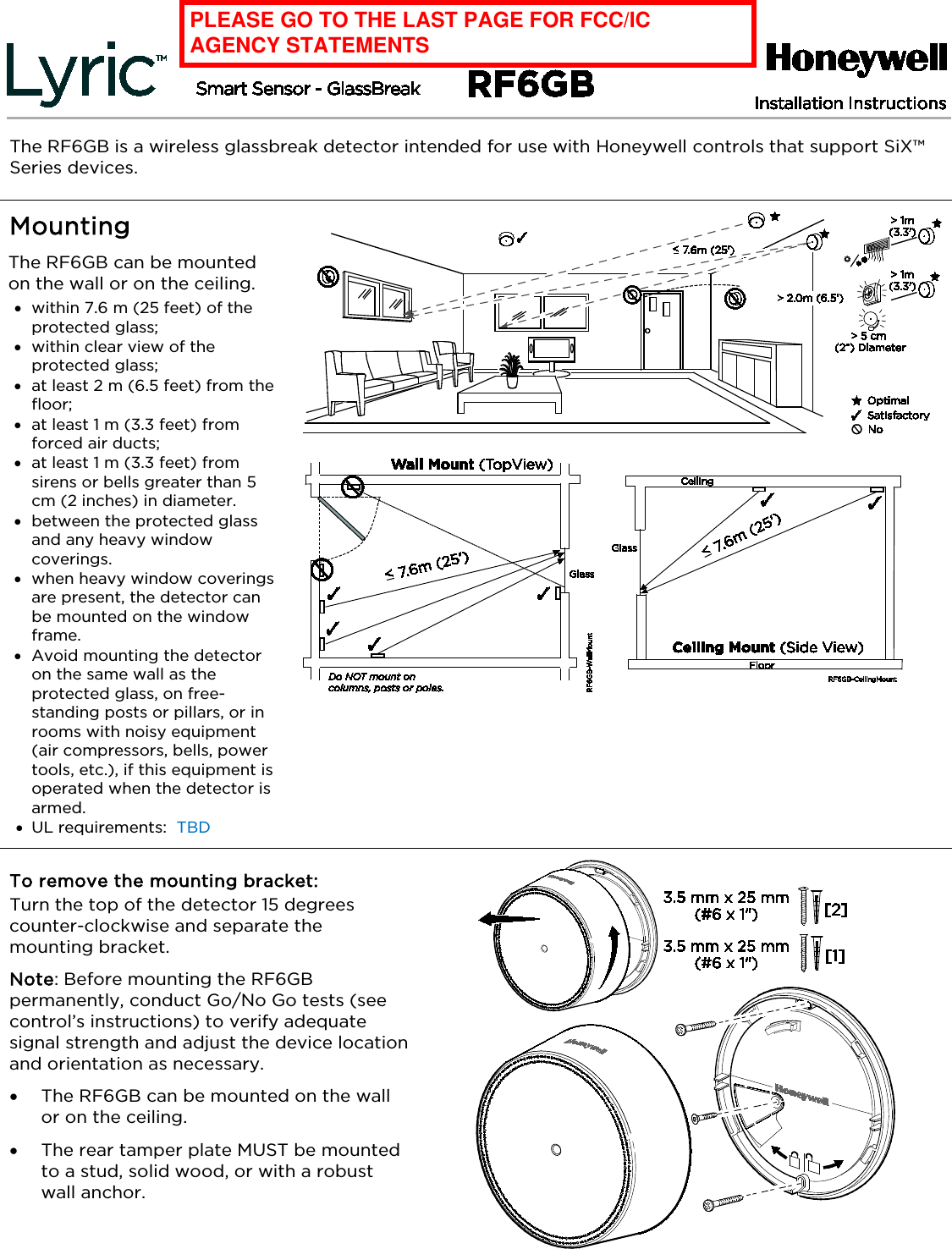
Installation Guide
![Enroll This device can be enrolled and programmed either before or after installation. 1. Set the Lyric Smart Controller in Programming Mode. 2. Remove the battery tab to activate the device and begin the enrollment process. 3. The RF6GB Green LED flashes during enrollment (about 8 seconds*) *Note: Depending on the signal strength between the device and the control, the enrollment period may take longer than 8 seconds. • The device sends its unique MAC ID address (Serial Number) and Services information to the control. • The control registers the device and displays the transmitter data on screen. 4. Enrollment is confirmed When the RF6GB Green LED is ON for 3 seconds [and the control beeps TBD]. 5. If the sensor is not successfully enrolled during the enrollment period, the LED turns off and the device powers down. Activate the tamper, power down and up again, or use the FG701 Glassbreak Simulator to restart the enrollment process. Note: Once enrolled in a system, the detector cannot be used with another control panel until it is removed from the current control panel. See the Control’s instructions for details on removing devices. Program the RF6GB Consult the Control’s instructions for programming the device in the system. Fault device features to “Learn” device “Services” in the control: - Tamper switch - Selectable Sensitivity Settings - Temperature sensing Temperature Sensing Temperature sensing range is 0 – 50°C / 32 – 122°F and is always enabled. Program the system to use the temperature information at the panel. Sensitivity Setting Approximate Range High 4.6-7.6m / 15-25 ft. Medium 3-4.6m / 10-15 ft. Low 1.5-3m / 5-10 ft. Lowest 0-1.5m / 0-5 ft. The RF6GB detector is Factory set at HIGH sensitivity. Change the sensitivity setting at the Control Panel.](https://usermanual.wiki/Ademco/8DLLGB500.Installation-Guide/User-Guide-2728690-Page-2.png)
![Specifications Battery: Panasonic CR123A, Duracell DL 123, Duracell DL 123A, Honeywell 466 Tamper: Cover and Wall RF Frequency: 2.4GHz Operating Temperature: 0° to 50° C / 32° to 122° F Relative Humidity: 5 – 95%, non-condensing Dimensions: 96 mm Diameter x 29mm Thick / 3.78” Diameter x 1.14” Thick Approval Listings RoHS FCC / IC ULC S306-03 UL 639 Protected Glass Types Chart [PRELIMINARY – TBD AFTER AGENCY TESTING] NOTE: The RF6GB is NOT recommended for protection of glass areas smaller than 27.6 cm x 27.6 cm (10-7/8 inches x 10-7/8 inches). Glass Type* Nominal Thickness Minimum Maximum Plate 2mm (3/32 in.) 10mm (3/8 in.) Tempered 3mm (1/8 in.) 10mm (3/8 in.) Laminated1, 3 3mm (1/8 in.) 14mm (9/16 in.) Wired 6mm (1/4 in.) 6mm (1/4 in.) Coated2, 3 3mm (1/8 in.) 6mm (1/4 in.) Sealed Insulating1,3 3mm (1/8 in.) [13mm (1/2 in.) overall] 6mm (1/4 in.) [19mm (3/4 in.) overall] * Minimum size for all types is 28cm (11 in.) square; glass must be framed in the wall or mounted in a barrier at least 0.9m (36 in.) wide. 1 Protected only if both plates in the unit are broken 2 Coated glass with security films up to 0.35mm (14 mils) thick (including films for solar protection) may be used. Evaluated with the these products: 3M® SCOTCHSHIELD® SH14CLARL – 0.35mm (14 mils), 4 ply film; Film Technologies International, Inc.’s GLASS-GARD GGLL 1200 has been evaluated with this product by Underwriters Laboratories, Inc. 3 In compliance with Underwriters Laboratories of Canada’s Standard for Intrusion Detection Units (CAN/ULC-S306-M89): a. Plate glass 3mm (1/8-in.) to 10mm (3/8-in.) can be used. b. ULC recognizes a maximum range for protecting sealed insulating glass, 1/8” laminated and coated glass of 3.8m (12.5 ft.); sensitivity should be set to High. FEDERAL COMMUNICATIONS COMMISSION & INDUSTRY CANADA STATEMENTS The user shall not make any changes or modifications to the equipment unless authorized by the Installation Instructions or User's Manual. Unauthorized changes or modifications could void the user's authority to operate the equipment. FCC / IC STATEMENT This device complies with Part 15 of the FCC Rules, and RSS-210 of Industry Canada. Operation is subject to the following two conditions: (1) This device may not cause harmful interference, and (2) This device must accept any interference received, including interference that may cause undesired operation. Cet appareil est conforme à la partie 15 des règles de la FCC & de RSS-210 des Industries Canada. Son fonctionnement est soumis aux conditions suivantes: (1) Cet appareil ne doit pas causer d’interférences nuisibles. (2) Cet appareil doit accepter toute interférence reçue y compris les interférences causant une reception indésirable. RF Exposure Warning – The antenna(s) used for this device must be installed to provide a separation distance of at least 7.8 inches (20 cm) from all persons and must not be co-located or operating in conjunction with any other antenna or transmitter except in accordance with FCC multi-transmitter product procedures. Mise en Garde Exposition aux Frequences Radio: L'antenne (s) utilisée pour cet émetteur doit être installée à une distance de séparation d'au moins 7,8 pouces (20 cm) de toutes les personnes. Support and Warranty REFER TO THE INSTALLATION INSTRUCTIONS FOR THE CONTROL WITH WHICH THIS DEVICE IS USED, FOR DETAILS REGARDING LIMITATIONS OF THE ENTIRE ALARM SYSTEM. For the latest U.S. warranty information, please go to www.honeywell.com/security/hsc/resources/wa or Please contact your local authorized Honeywell representative for product warranty information. 2014 Honeywell International Inc. Honeywell and is a registered trademark of Honeywell International Inc. All other trademarks are the properties of their respective owners. All rights reserved. DOC CODE 128B BAR CODE HERE P/N 800-19202GB 01/15 Rev BETA 2 Corporate Center Drive, Suite 100 P.O. Box 9040, Melville, NY 11747 www.honeywell.com/security](https://usermanual.wiki/Ademco/8DLLGB500.Installation-Guide/User-Guide-2728690-Page-4.png)