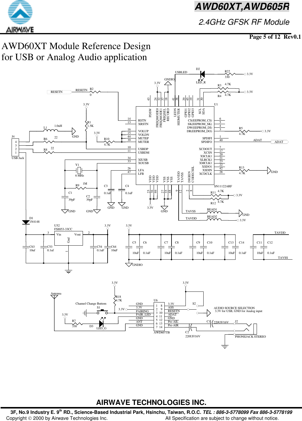
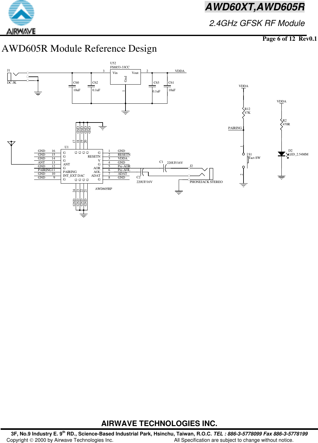
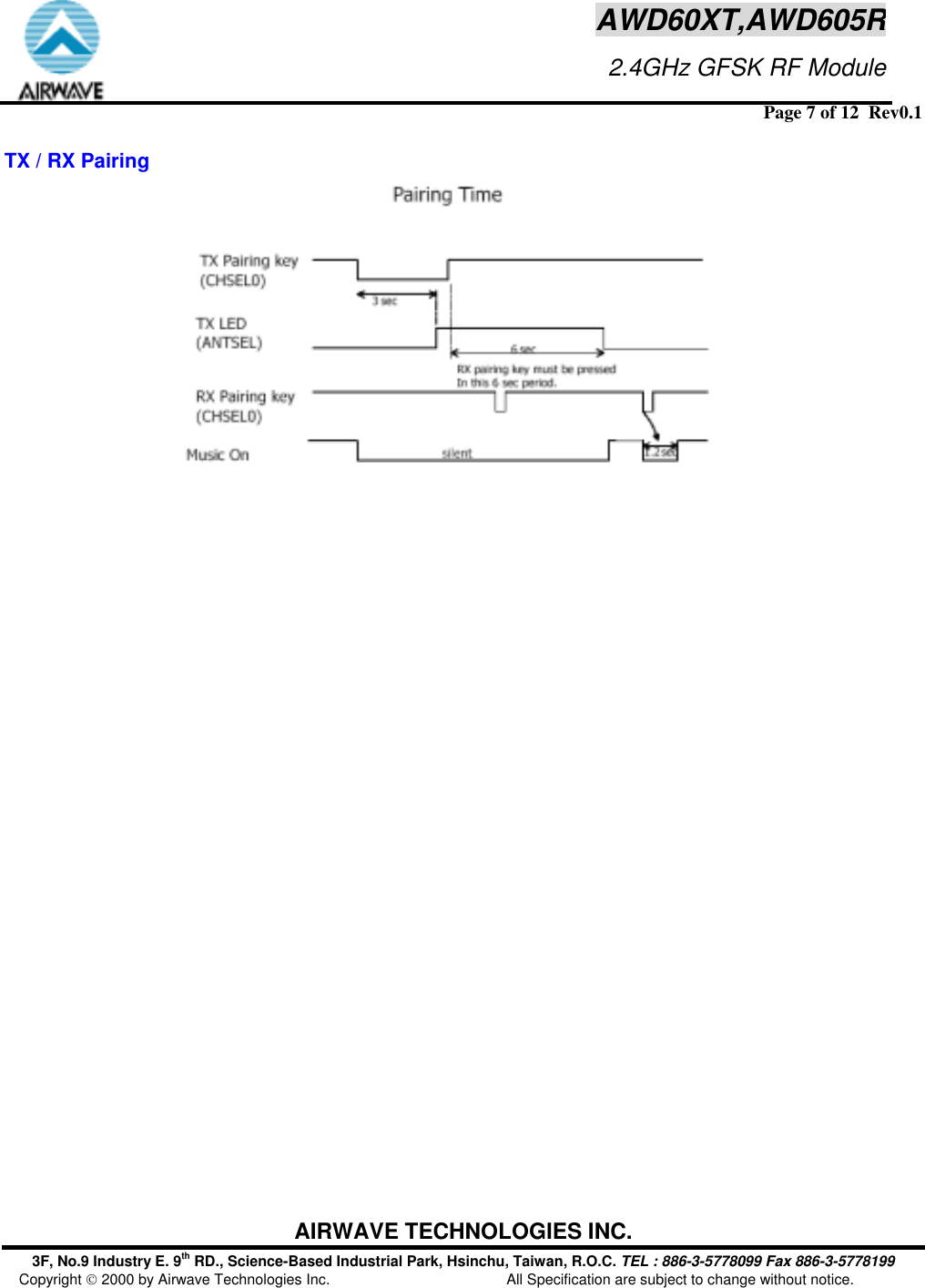
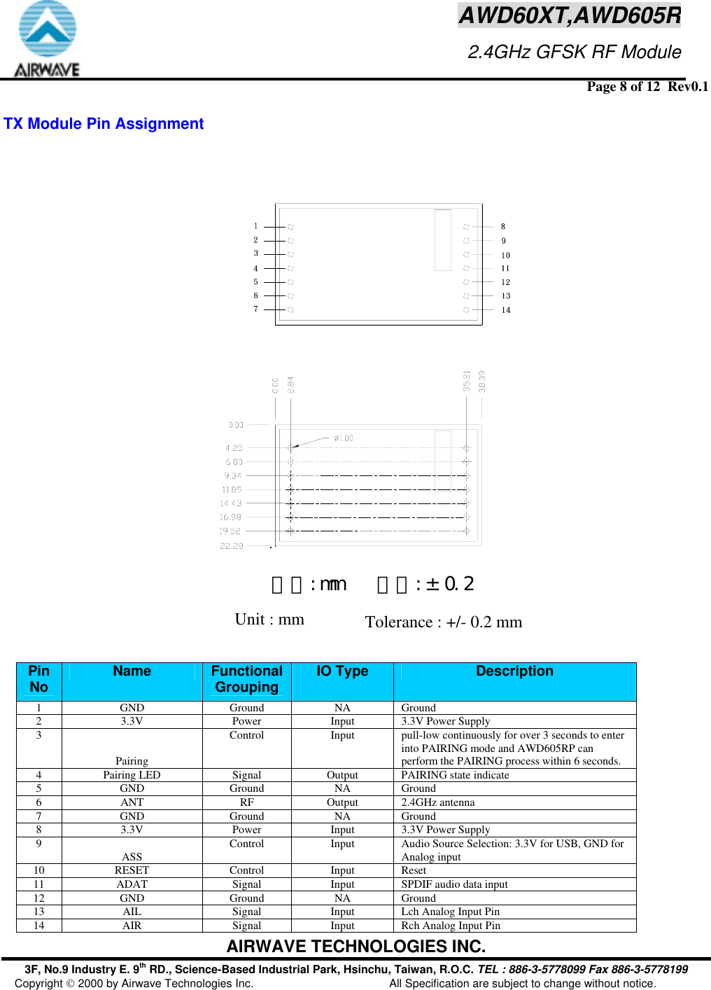
Airwave Technologies AWD60XT 2.4GHz Wireless Digital Audio Transmitter Module User Manual Users manual

Airwave Technologies Inc 2.4GHz Wireless Digital Audio Transmitter Module Users manual

Users manual

 Page 1 of 12  Rev0.1 AIRWAVE TECHNOLOGIES INC. 3F, No.9 Industry E. 9th RD., Science-Based Industrial Park, Hsinchu, Taiwan, R.O.C. TEL : 886-3-5778099 Fax 886-3-5778199 Copyright  2000 by Airwave Technologies Inc.  All Specification are subject to change without notice.  AWD60XT,AWD605R                     2.4GHz GFSK RF ModulePreliminary  Rev0.1          2006/8/28 Features  •  Proprietary audio compression/decompression(LDAP) for wireless transmission •  Low audio latency(~3.8ms in total) •  Highly Robust Forward Error Correction (FEC) •  8 frequency channels •  RF channel data rate:1.152 Mbps •  16-Bit ID codes to provide TX / RX pairing •  Auto channel scanning mechanism provided •  Optimized auto muting mechanism for received corrupted data by the receiver •  High Sensitivity of typically –85dBm •  High Output Power of typically +8.5dBm •  RoHs Compliant •  Stereo ΔΣADC •  48kHz Audio Sampling rate •  High S/N ratio of typically 82 dB •  Both S/PIDF Data and Analog Audio Input Formats     Applications  •  Low Cost/High Performance Wireless Audio   Wireless Surround Rear Speakers  High Performance Digital Audio Link  Wireless Headphone/Earphone  Wireless USB Transmitter  Wireless Skype phone •  FCC CFR47,Part 15,ETSI  EN 300 328,EN 300 440 and ARIB STD-T-66 Compliant Radio   General Description  The RF module transmitter employed GFSK modulation to deliver high-speed data rate up to 1.152Mbps.  The RF module receiver with –85dBm or better sensitivity allows system to achieve at least 300 feet transmission for line-of-sight application in open site.
 Page 2 of 12  Rev0.1 AIRWAVE TECHNOLOGIES INC. 3F, No.9 Industry E. 9th RD., Science-Based Industrial Park, Hsinchu, Taiwan, R.O.C. TEL : 886-3-5778099 Fax 886-3-5778199 Copyright  2000 by Airwave Technologies Inc.  All Specification are subject to change without notice. AWD60XT,AWD605R                     2.4GHz GFSK RF ModuleTx Module Absolute Maximum Ratings Parameter  Condition  Min.  Typ  Max  Units Supply voltage   Vs  3.0 3.3 3.6  V Storage temperature  Tstg  -40 25 +125 ℃ Operating temperature  To  0 25 +55 ℃ Rx Module Absolute Maximum Ratings Parameter  Condition  Min.  Typ  Max  Units Supply voltage   Vs  3.0 3.3  3.6  V Storage temperature  Tstg  -40 25 +125 ℃ Operating temperature  To  0 25 +55 ℃ Input RF level  Prf    +10 dBm  Genernal  Parameter  Condition  Min.  Typ  Max  Units Audio latency     3.8   ms Tx,Rx pairing  ID Code   16   bit S/N ratio     82   dB  Tx Module  Parameter  Condition  Min.  Typ  Max  Units Supply voltage   Vs  3.0 3.3 3.6  V Supply current     89   mA Operating Frequency    2400  2483.5 MHz Transmission Power    8 8.5 9.5 dBm Modulation Type  GFSK       Channel Frequency  Peak power position under no Data in.  -0.1  2401.9202412.2882422.6562433.0242448.5762458.9442469.312+0.1  MHz
 Page 3 of 12  Rev0.1 AIRWAVE TECHNOLOGIES INC. 3F, No.9 Industry E. 9th RD., Science-Based Industrial Park, Hsinchu, Taiwan, R.O.C. TEL : 886-3-5778099 Fax 886-3-5778199 Copyright  2000 by Airwave Technologies Inc.  All Specification are subject to change without notice. AWD60XT,AWD605R                     2.4GHz GFSK RF Module2479.680Channel Spacing     10.368   MHz Frequency Deviation     +/-0.1   MHz Audio Input Level  peak to peak value   2.0  V Audio Input Impedance   20k   Ohm Data Rate     1.152   Mbps Audio Sampling Rate     48   KHz Pairing LED voltage  Pull High Resistor       Tx/Rx Pairing setting  tact switch   3.3    V Reset pin  tact switch
 Page 4 of 12  Rev0.1 AIRWAVE TECHNOLOGIES INC. 3F, No.9 Industry E. 9th RD., Science-Based Industrial Park, Hsinchu, Taiwan, R.O.C. TEL : 886-3-5778099 Fax 886-3-5778199 Copyright  2000 by Airwave Technologies Inc.  All Specification are subject to change without notice. AWD60XT,AWD605R                     2.4GHz GFSK RF Module    Rx Module  Parameter  Condition  Min.  Typ  Max  Units Supply voltage   Vs  3.0 3.3  3.6  V Supply current     99   mA Operating Frequency    2400  2483.5 MHz Rx Sensitivity  BER=1e-3 when 1.152Mbps input  -85   dBm Image Rejection  Relative to 2.4-2.4835GHz power 47    dBc Audio Output Level      2.6    Vpp Audio Output Impedance      16    Ohm Audio frequency response 3dB bandwidth  20  20k Hz Data Rate     1.152    Mbps Adjacent channel rejection +/- 5MHz offset the central frequency   >45   dB Tx/Rx Pairing setting  tact switch
 Page 5 of 12  Rev0.1 AIRWAVE TECHNOLOGIES INC. 3F, No.9 Industry E. 9th RD., Science-Based Industrial Park, Hsinchu, Taiwan, R.O.C. TEL : 886-3-5778099 Fax 886-3-5778199 Copyright  2000 by Airwave Technologies Inc.  All Specification are subject to change without notice. AWD60XT,AWD605R                     2.4GHz GFSK RF ModuleAWD60XT Module Reference Design  for USB or Analog Audio application C540.1uFC530.1ufVin3Gnd1Vout 2U52FS8853-33CC1234J4USB JackR6 22R11.5KR8 22L1 1.0uH3.3VGNDGNDIO3.3V3.3VADATY16 MHzC139pF C239pFR9 1MGND GNDGNDIOC60.1uF3.3V3.3V3.3V3.3VGND GNDGNDFREQSEL 37HIDMUTER 38MUTER39 SPDIFO 40LEDN 41XSDIN 42PDSW 43MUTEP44GPIO2 45VDD46LFB47VSS48SDA 30GPIO1 29FREQMODE0 24XMCLK1 23XSDO1 22XLRCK1 21XSCLK1 20GPIO3 19RECORD 18XCSN 17VOLUP16VOLDN15RSTN14XRSTN13XCDCLK 28VSS27LFA26VDD25VDD36VSS35XIUSB34XOUSB33FREQMODE1 32SCL 31SPDIFI 1DIGIEN2DR(EEPROM_DO) 3DW(EEPROM_DI) 4SK(EEPROM_SK) 5CS(EEPROM_CS) 6TAVSS12USBDM11 USBDP10TAVDD9CODECSEL8XCDOUT 7U1SN11122ARFR104.7K3.3VR11 4.7K3.3VR12 4.7KR134.7KR54.7KR3 4.7KR4 4.7KC40.1uFC30.1uFGND GNDRESETN R20BEAD2BEAD1TAVSSTAVDDC80.1uFC100.1uFC120.1uFTAVDDTAVSSGNDPAIRINGPAIR_LEDGNDANTGNDS1Channel Change ButtomR184.7KASSRESETNADATGNDPre-AILPre-AIR3.3V 3.3V3.3VUSBLED R22330 3.3VRESETNR7330 D3 LED_GD11N4148C140.1uFD2LED_RC6310ufC510uFC710uFC910uFC1310uFC1110uFC6410uFADAT1234567141312111098U6AWD607TB3.3V3.3V3.3V 3.3V S2AUDIO SOURCE SELECTIONC1 220UF/16VC2220UF/16VJ2PHONEJACK STEREO 3.3V for USB, GND for Analog inputAntenna
 Page 6 of 12  Rev0.1 AIRWAVE TECHNOLOGIES INC. 3F, No.9 Industry E. 9th RD., Science-Based Industrial Park, Hsinchu, Taiwan, R.O.C. TEL : 886-3-5778099 Fax 886-3-5778199 Copyright  2000 by Airwave Technologies Inc.  All Specification are subject to change without notice. AWD60XT,AWD605R                     2.4GHz GFSK RF ModuleAWD605R Module Reference Design C630.1uFC620.1uFVDDAR1247KPAIRINGVDDAVDDAR2470RGNDGNDGND GNDGNDRESETNGNDANTGNDPAIRINGGNDVDDAGNDPre-AOLPre-AORADATGNDGNDGNDGNDVin3Gnd1Vout 2U52FS8853-33CCC6010uFC6110uFD2LED_2.54MM12S1Tact-SWC1 220UF/16VC2220UF/16VJ2PHONEJACK STEREOJ1DC JKGNDGNDGNDGNDG1RESETN 2V3G4AOR 5AOL 6ADAT 7G8G9INT_EXT DAC10 PAIRING11 G12 ANT13 G14 G15 G16G21 G22 G18G17G23 G24G20G19U1AWD605RP
 Page 7 of 12  Rev0.1 AIRWAVE TECHNOLOGIES INC. 3F, No.9 Industry E. 9th RD., Science-Based Industrial Park, Hsinchu, Taiwan, R.O.C. TEL : 886-3-5778099 Fax 886-3-5778199 Copyright  2000 by Airwave Technologies Inc.  All Specification are subject to change without notice. AWD60XT,AWD605R                     2.4GHz GFSK RF Module TX / RX Pairing
 Page 8 of 12  Rev0.1 AIRWAVE TECHNOLOGIES INC. 3F, No.9 Industry E. 9th RD., Science-Based Industrial Park, Hsinchu, Taiwan, R.O.C. TEL : 886-3-5778099 Fax 886-3-5778199 Copyright  2000 by Airwave Technologies Inc.  All Specification are subject to change without notice. AWD60XT,AWD605R                     2.4GHz GFSK RF Module TX Module Pin Assignment   單位:mm    公差:± 0.2  Pin No  Name  FunctionalGrouping IO Type  Description 1 GND  Ground NA Ground 2  3.3V  Power  Input  3.3V Power Supply 3 Pairing Control Input pull-low continuously for over 3 seconds to enter into PAIRING mode and AWD605RP can perform the PAIRING process within 6 seconds. 4  Pairing LED  Signal  Output  PAIRING state indicate 5 GND  Ground NA  Ground 6  ANT  RF  Output   2.4GHz antenna 7 GND  Ground NA Ground 8  3.3V  Power  Input  3.3V Power Supply 9  ASS  Control  Input  Audio Source Selection: 3.3V for USB, GND for Analog input 10 RESET  Control Input Reset 11  ADAT  Signal  Input  SPDIF audio data input 12 GND  Ground NA Ground 13  AIL  Signal  Input  Lch Analog Input Pin 14  AIR  Signal  Input  Rch Analog Input Pin Unit : mm  Tolerance : +/- 0.2 mm
 Page 9 of 12  Rev0.1 AIRWAVE TECHNOLOGIES INC. 3F, No.9 Industry E. 9th RD., Science-Based Industrial Park, Hsinchu, Taiwan, R.O.C. TEL : 886-3-5778099 Fax 886-3-5778199 Copyright  2000 by Airwave Technologies Inc.  All Specification are subject to change without notice. AWD60XT,AWD605R                     2.4GHz GFSK RF Module單位:mm    公差:± 0.2 Tolerance : +/- 0.2 mm Unit : mm
 Page 10 of 12  Rev0.1 AIRWAVE TECHNOLOGIES INC. 3F, No.9 Industry E. 9th RD., Science-Based Industrial Park, Hsinchu, Taiwan, R.O.C. TEL : 886-3-5778099 Fax 886-3-5778199 Copyright  2000 by Airwave Technologies Inc.  All Specification are subject to change without notice. AWD60XT,AWD605R                     2.4GHz GFSK RF Module RX Module Pin Assignment  Unit:mm    Tolerance:± 0.2
 Page 11 of 12  Rev0.1 AIRWAVE TECHNOLOGIES INC. 3F, No.9 Industry E. 9th RD., Science-Based Industrial Park, Hsinchu, Taiwan, R.O.C. TEL : 886-3-5778099 Fax 886-3-5778199 Copyright  2000 by Airwave Technologies Inc.  All Specification are subject to change without notice. AWD60XT,AWD605R                     2.4GHz GFSK RF ModulePin No  Name  Functional Grouping  IO Type  Description 1 GND  Ground NA Ground 2 RESETN  Control Input Reset 3  3.3V  Power  Input  3.3V Power Supply 4 GND  Ground NA Ground 5  AOR  Signal  Output  Rch Analog Output Pin 6  AOL  Signal  Output  Lch Analog Output Pin 7 NC    NA NA 8 GND  Ground NA Ground 9 GND  Ground NA Ground 10 GND  Ground NA Ground 11 Pairing Control  Input  After continuously pulling-low for over 3 seconds on AWD607TP, AWD605RP enters into PAIRING mode and the PAIRING process can be performed for the next 6 seconds. 12 GND  Ground NA Ground 13  ANT  RF  Input   2.4GHz antenna 14 GND  Ground NA Ground 15 RSSI  Signal Output Received signal strength indicator output 16 GND  Ground NA Ground
 Page 12 of 12  Rev0.1 AIRWAVE TECHNOLOGIES INC. 3F, No.9 Industry E. 9th RD., Science-Based Industrial Park, Hsinchu, Taiwan, R.O.C. TEL : 886-3-5778099 Fax 886-3-5778199 Copyright  2000 by Airwave Technologies Inc.  All Specification are subject to change without notice. AWD60XT,AWD605R                     2.4GHz GFSK RF Module Unit:mm    Tolerance:± 0.2
  Federal Communication Commission Interference Statement This equipment has been tested and found to comply with the limits for a Class B digital device, pursuant to Part 15 of the FCC Rules. These limits are designed to provide reasonable protection against harmful interference in a residential installation. This equipment generates, uses and can radiate radio frequency energy and, if not installed and used in accordance with the instructions, may cause harmful interference to radio communications. However, there is no guarantee that interference will not occur in a particular installation. If this equipment does cause harmful interference to radio or television reception, which can be determined by turning the equipment off and on, the user is encouraged to try to correct the interference by one of the following measures: • Reorient or relocate the receiving antenna. • Increase the separation between the equipment and receiver. • Connect the equipment into an outlet on a circuit different from that to which the receiver is connected. • Consult the dealer or an experienced radio/TV technician for help. This device complies with Part 15 of the FCC Rules. Operation is subject to the following two conditions: (1) This device may not cause harmful interference, and (2) this device must accept any interference received,including interference that may cause undesired operation. FCC Caution: Any changes or modifications not expressly approved by the party responsible for compliance could void the user's authority to operate this equipment. IMPORTANT NOTE: FCC Radiation Exposure Statement: This equipment complies with FCC radiation exposure limits set forth for an uncontrolled environment. This equipment should be installed and operated with minimum distance 20cm between the radiator & your body. This transmitter must not be co-located or operating in conjunction with any other antenna or transmitter.  " This equipment must be installed and operated in accordance with provided instructions and the antenna(s) used for this transmitter must be installed to provide a separation distance of at least 20 cm from all persons and must not be co-located or operating in conjunction with any other antenna or transmitter. End-users and installers must be provide with antenna installation instructions and transmitter operating conditions for satisfying RF exposure compliance. "

Navigation menu