Alvarion Technologies EXTR-50 BreezeMAX Extreme 5.4 Base Station User Manual Extreme BTS QIG
Alvarion Technologies Ltd. BreezeMAX Extreme 5.4 Base Station Extreme BTS QIG
Contents
- 1. user installation manual
- 2. Updated user manual Correspondance 39238
- 3. Professional Installer qualifications and Quick Installation guide
- 4. User manual 1
- 5. User manual 2
Professional Installer qualifications and Quick Installation guide
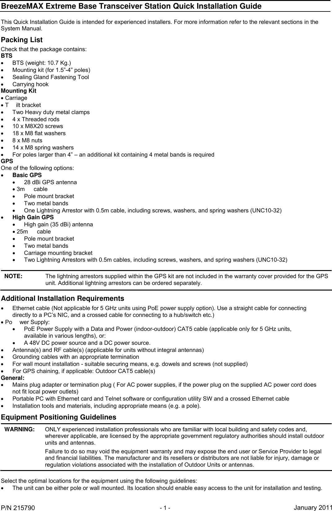
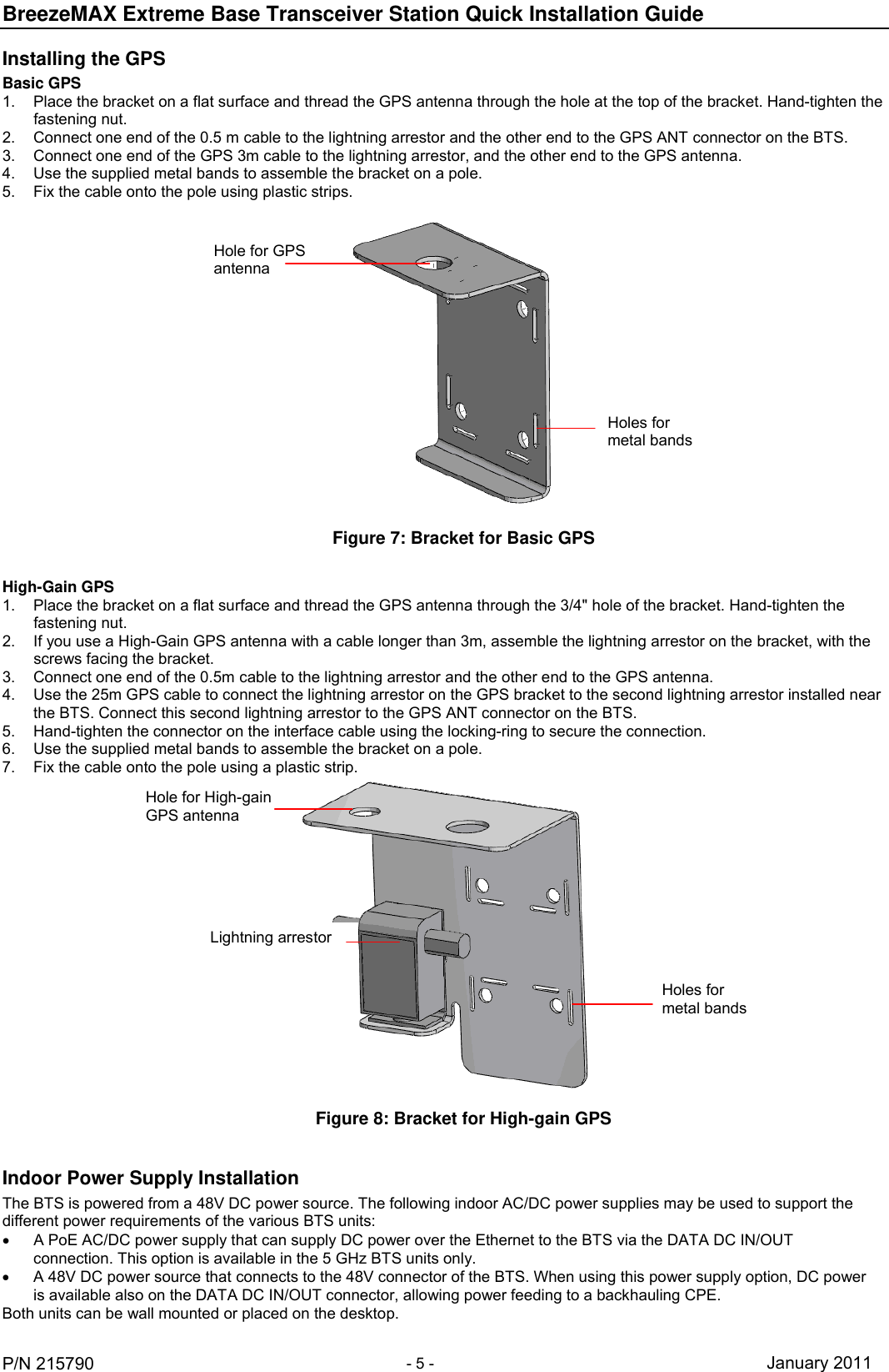
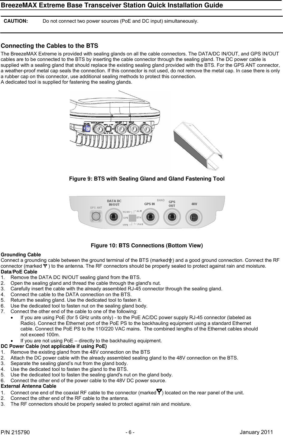
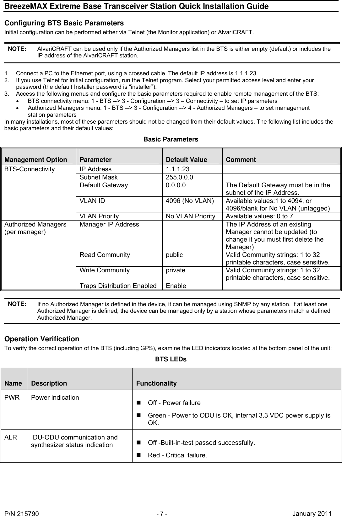
![BreezeMAX Extreme Base Transceiver Station Quick Installation Guide P/N 215790 - 3 - January 2011 Installing the BTS 1. Assemble the tilt bracket on the BTS and fasten its M8 screws. Apply torque of 80 [Lib*In] = 9 [N*m] Figure 2: Assembling the Tilt Bracket on the BTS Carrying groovesBTS Tilt bracket M8X20 screws 2. Install a lightning arrestor (part of the GPS kit) at the designated location at the bottom of the carriage. 3. Connect one end of the 0.5m cable to the lightning arrestor and the other end to the GPS ANT connector on the BTS. NOTE: Some units are supplied with a separate pole-mounting bracket for the lightning arrestor. Instead of attaching the lightning arrestor to the carriage, install this bracket on the pole as close to the BTS as possible, allowing connecting the lightning arrestor to the GPS connector on the BTS. The lightning arrestors supplied within the GPS kit are not included in the warranty cover provided for the GPS unit. Additional lightning arrestors can be ordered separately. Figure 3: Assembling the Lightning Arrestor on the Carriage Carriage Lightning arrestor Hole for lightning arrestor 4. Do one of the following: For poles up to 4” - Thread the four rods through the carriage. Insert the threaded rods with the grooves pointing outward, as these grooves enable you to use a screwdriver to fasten the rods to the unit. Attach the carriage and the clamps to the pole and tighten on both sides using the supplied washers, spring washers and nuts. Apply torque of 80 [Lib*In] = 9 [N*m]. For poles larger than 4” - Thread the four metal bands through the grooves on the carriage and fasten. For wall mount installation - mark the exact location of the holes to drill on the wall. Drill the holes, and use four metal dowels and screws to affix the carriage to the wall.](https://usermanual.wiki/Alvarion-Technologies/EXTR-50.Professional-Installer-qualifications-and-Quick-Installation-guide/User-Guide-1423999-Page-3.png)
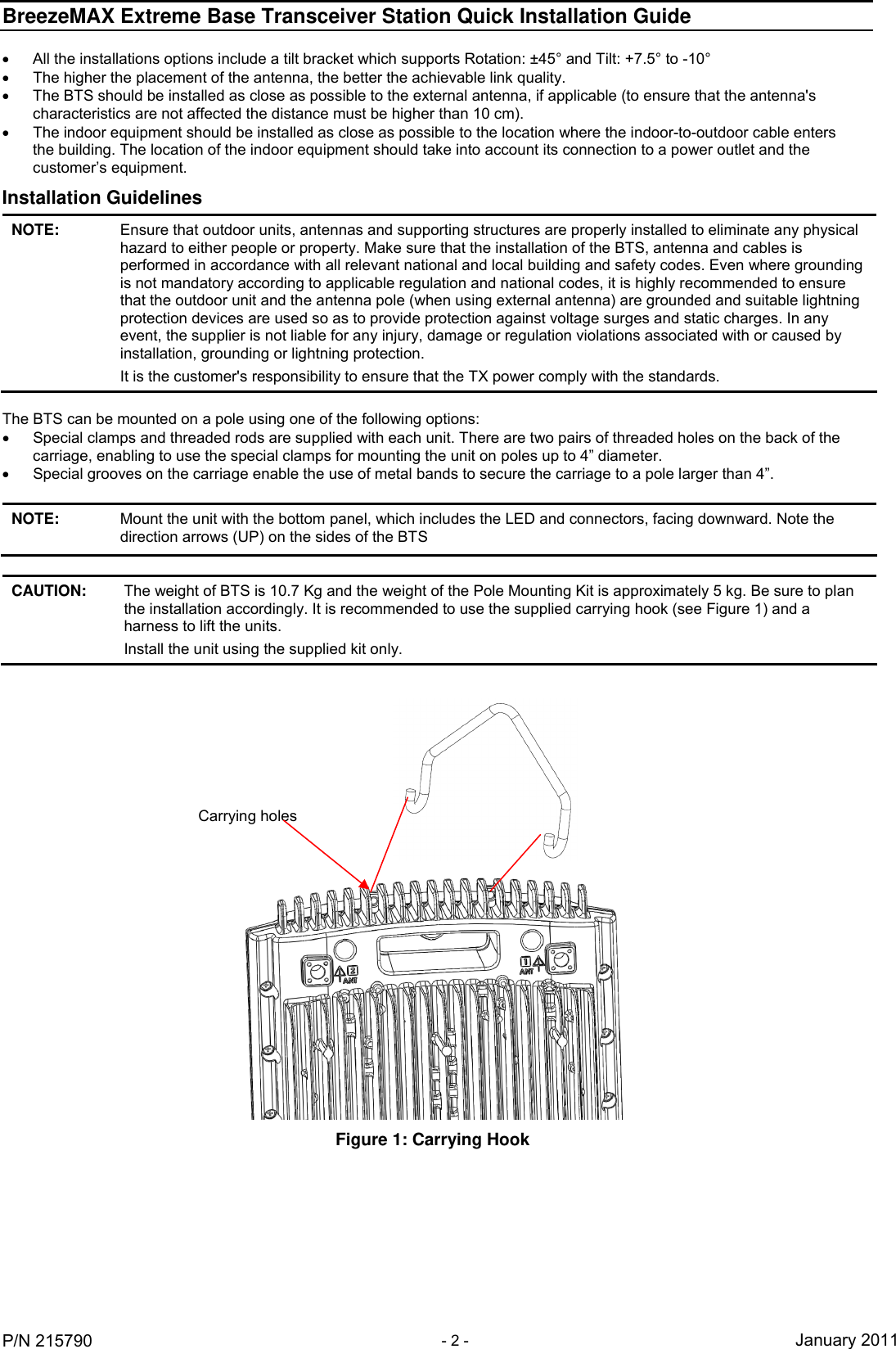
![BreezeMAX Extreme Base Transceiver Station Quick Installation Guide P/N 215790 - 4 - January 2011 Figure 4: Assembling the Carriage on 1.5”-4” Poles Using Clamps Figure 5: Assembling the Carriage on Poles Larger than 4” Using Metal Bands Nuts, washers and spring washers Clamps Rods Holes for wall mount (x4)Tilt control screwMetal bandsTilt control screw 5. Insert the Tilt Control screws into the middle-side hole of the carriage on both sides. 6. Hang the BTS with the tilt bracket on the Tilt-control screws of the BTS carriage. 7. Attach and fasten all the screws at both sides of the BTS carriage. Do not over tighten. 8. If required, slightly release the tilt bracket screws to enable rotation and the Tilt Control screws to enable tilting; adjust the BTS position and tighten the screws. Apply torques of 45 [Lib*In.] = 5 [N*m] to the M6 Tilt-control screws, and 80 [Lib*In] = 9 [N*m] to the M8 screws. Figure 6: BTS Mounted on a 1.5''-4'' Pole (with Clamps), and on Pole Larger than 4” (with Metal Bands)](https://usermanual.wiki/Alvarion-Technologies/EXTR-50.Professional-Installer-qualifications-and-Quick-Installation-guide/User-Guide-1423999-Page-4.png)