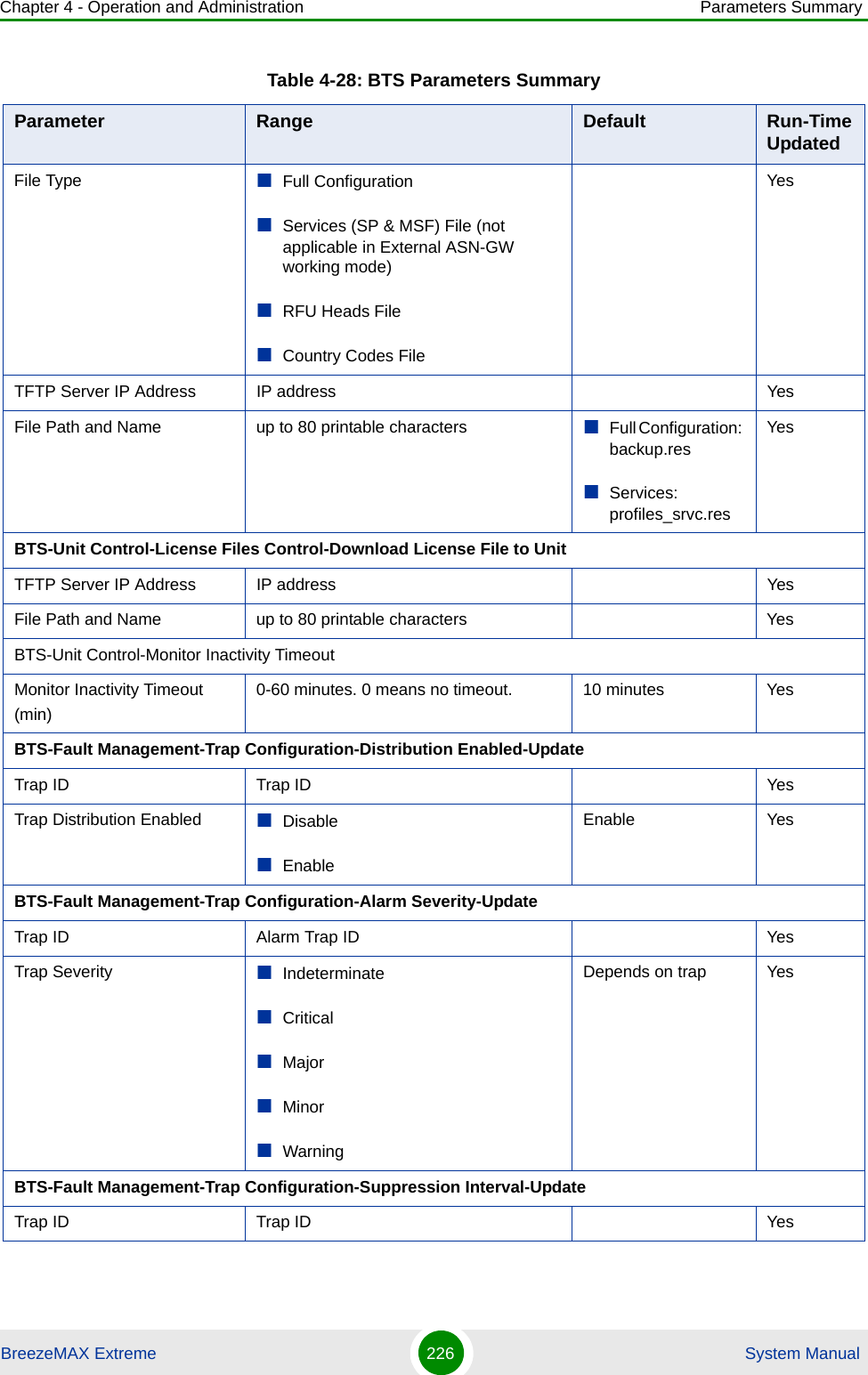
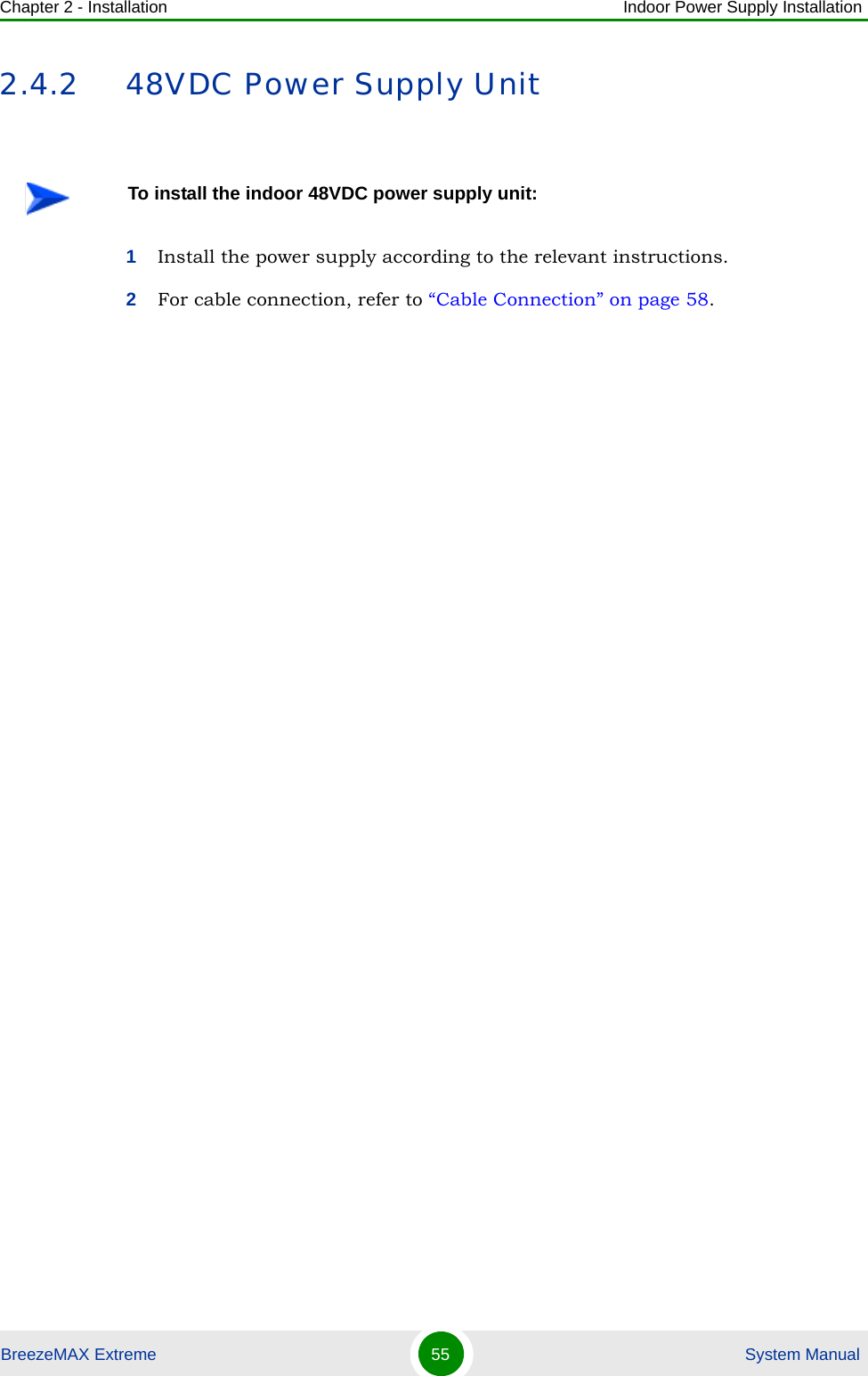
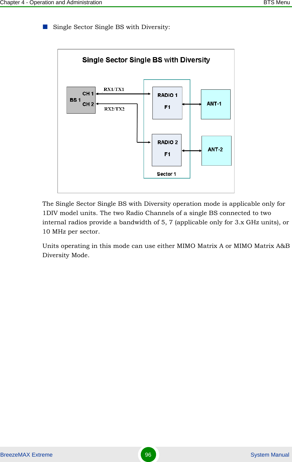
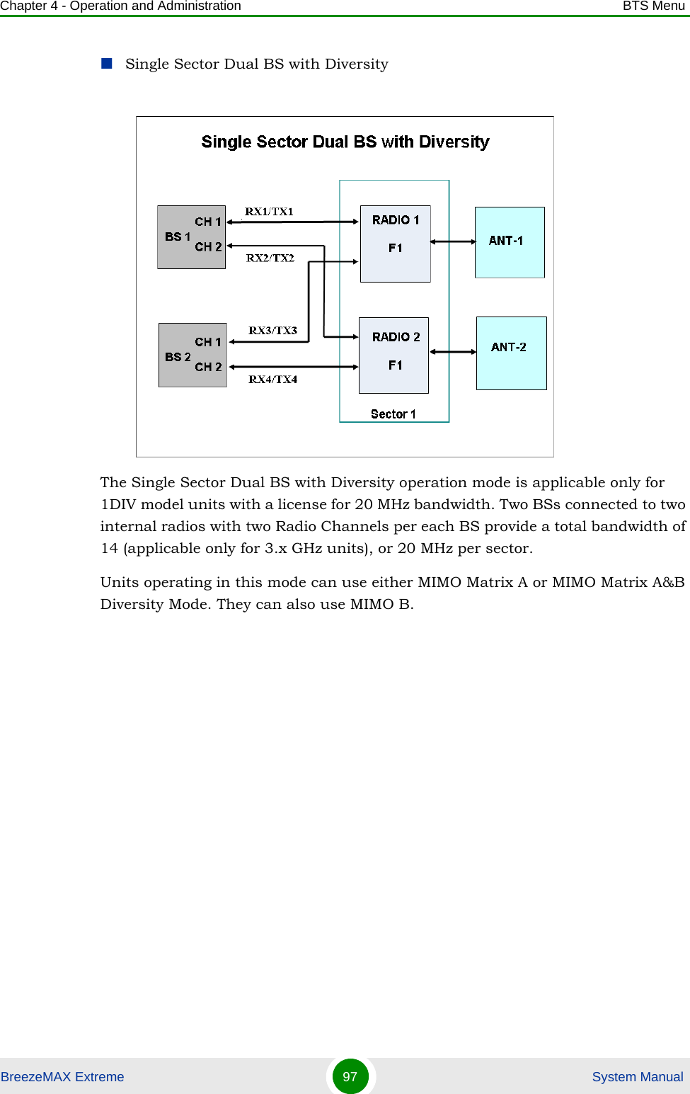
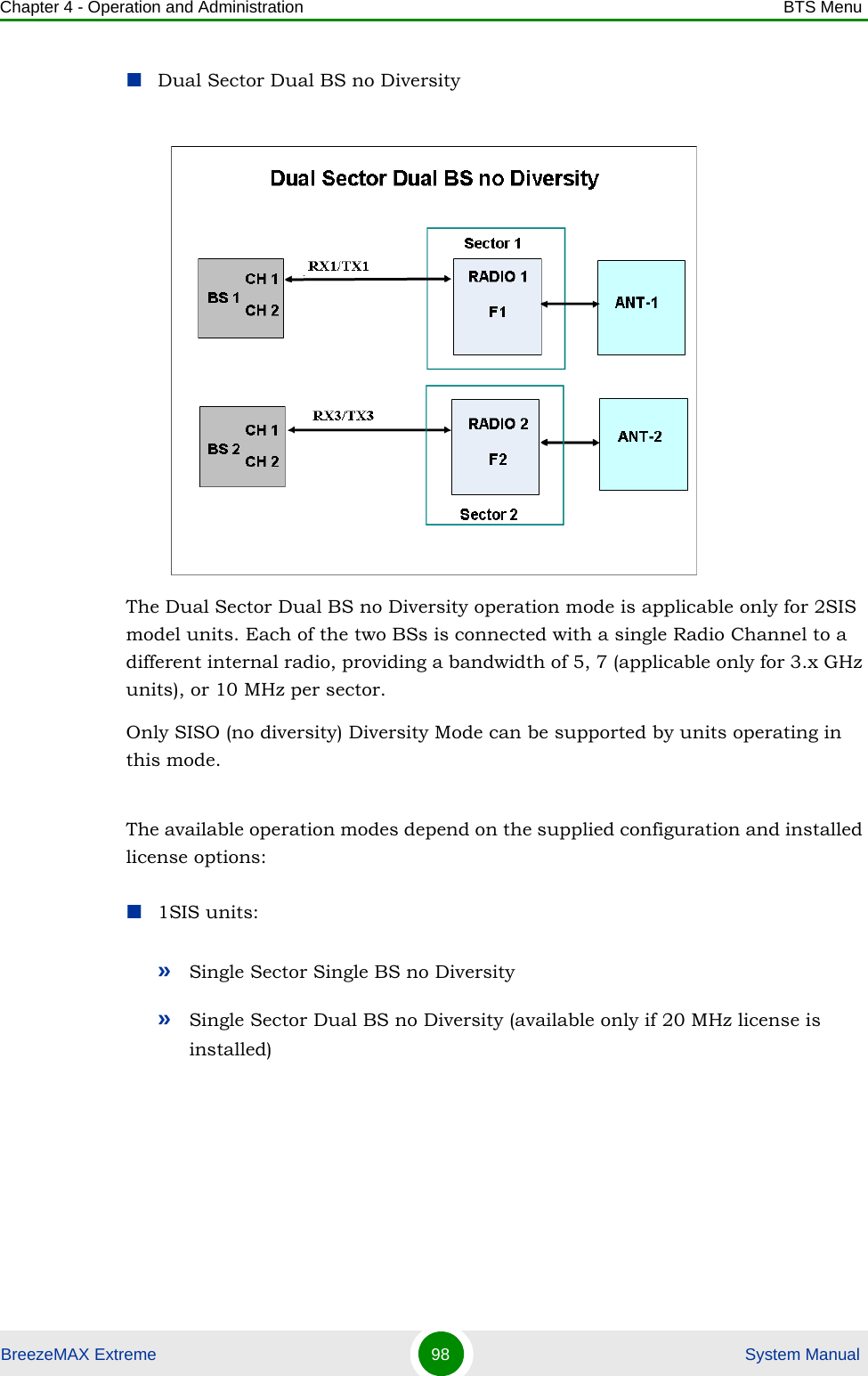
Alvarion Technologies EXTR-50 BreezeMAX Extreme 5.4 Base Station User Manual BMAX Extreme System Manual
Alvarion Technologies Ltd. BreezeMAX Extreme 5.4 Base Station BMAX Extreme System Manual
Contents
- 1. user installation manual
- 2. Updated user manual Correspondance 39238
- 3. Professional Installer qualifications and Quick Installation guide
- 4. User manual 1
- 5. User manual 2
Updated user manual Correspondance 39238
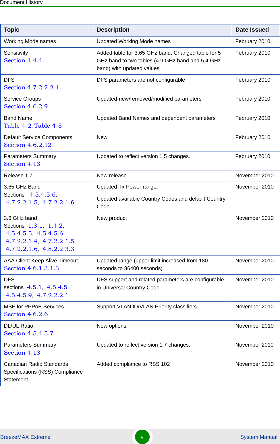
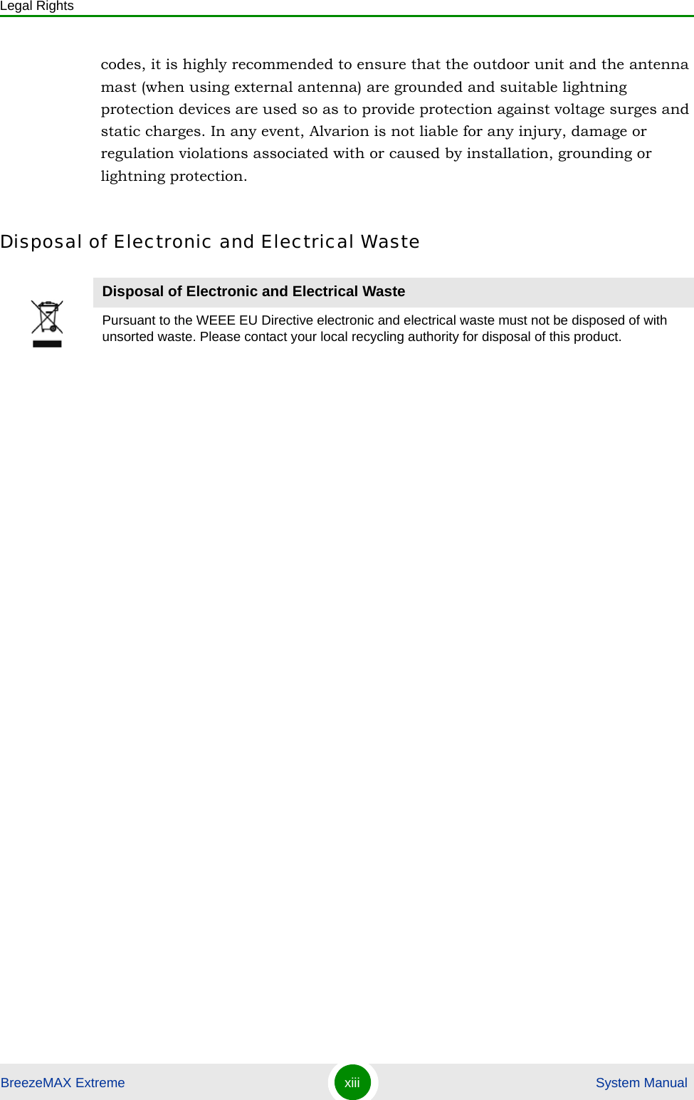
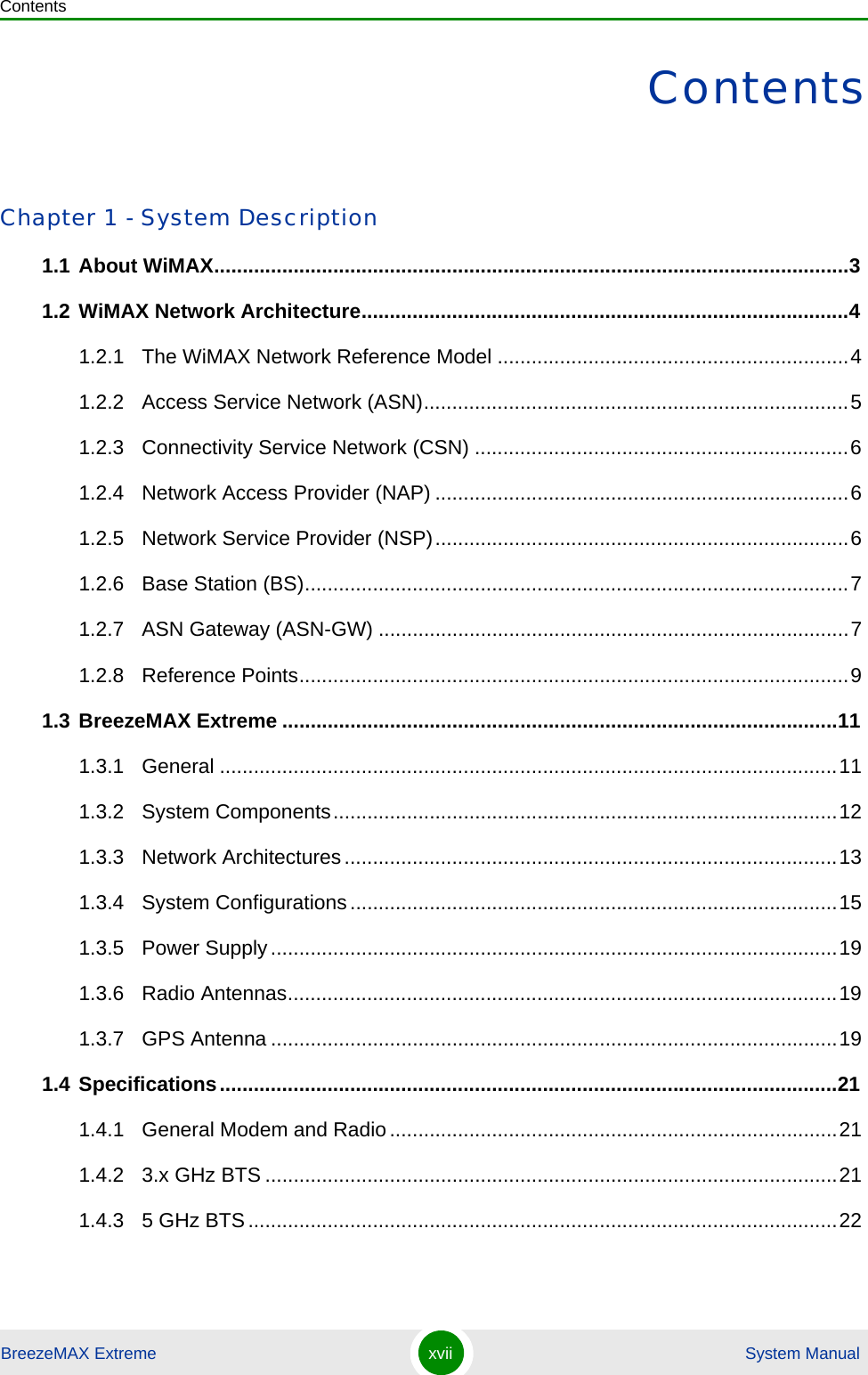
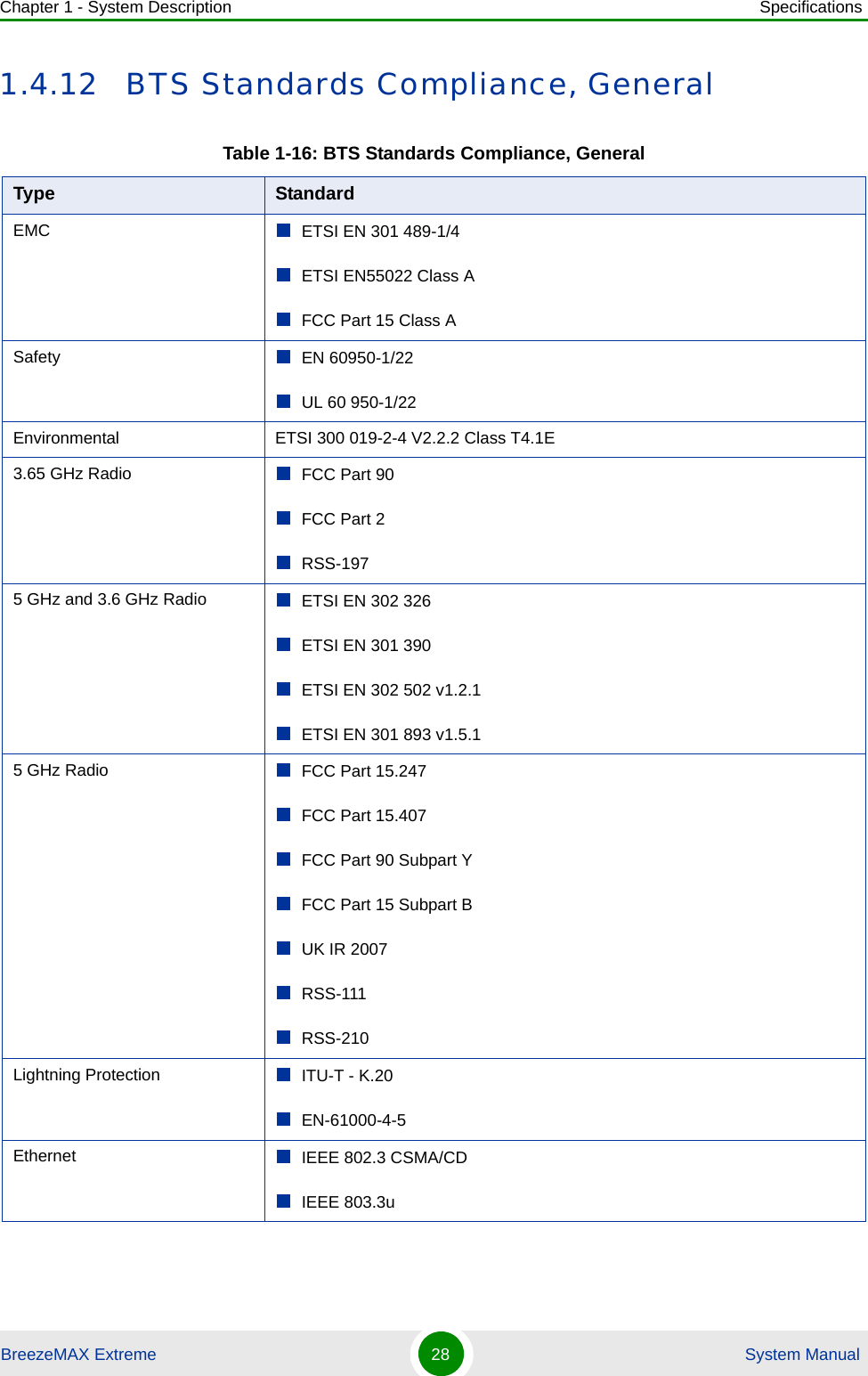
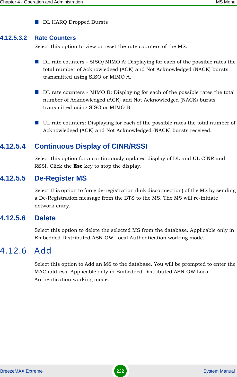
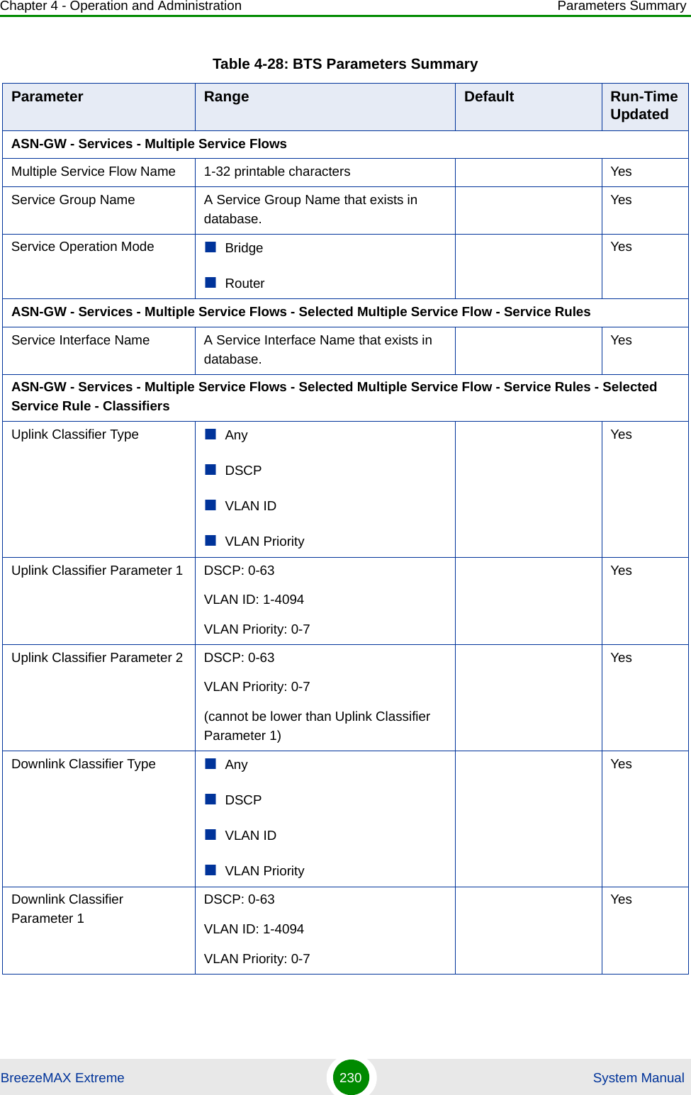
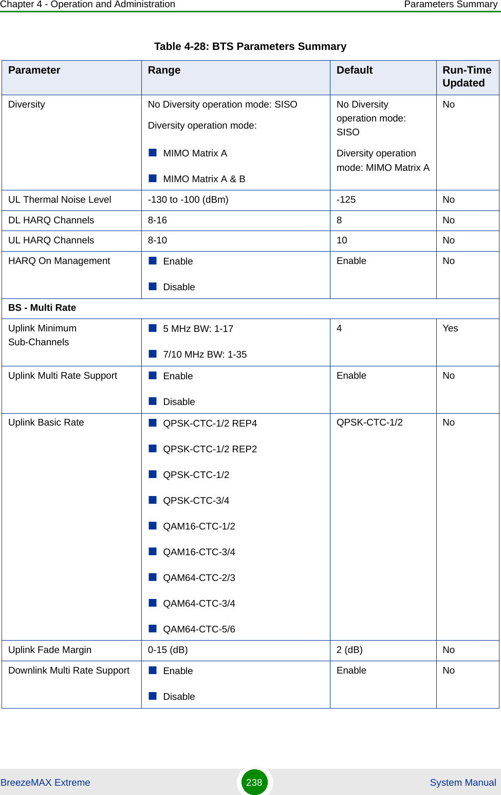
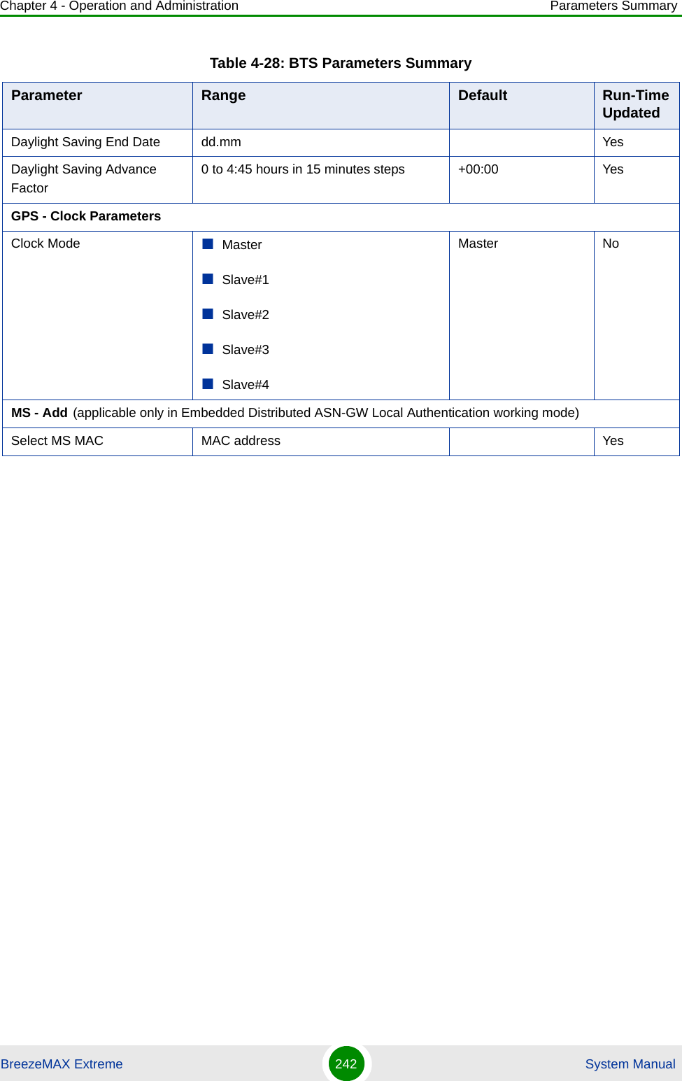
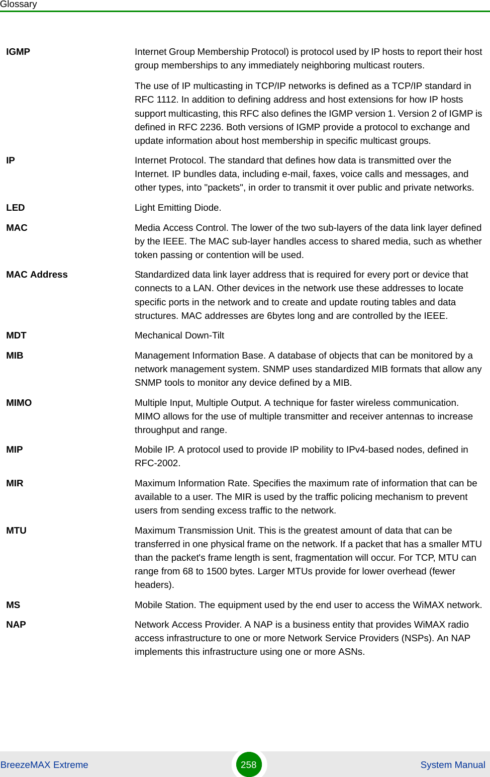
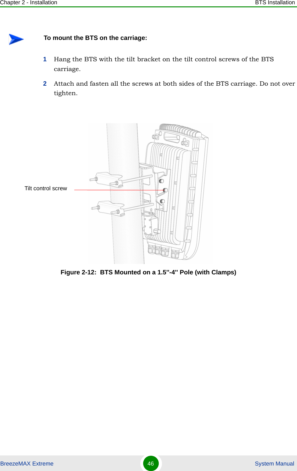
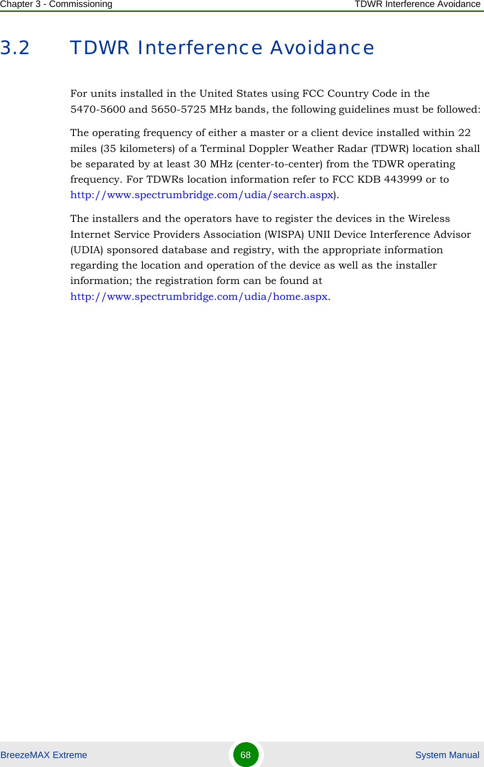
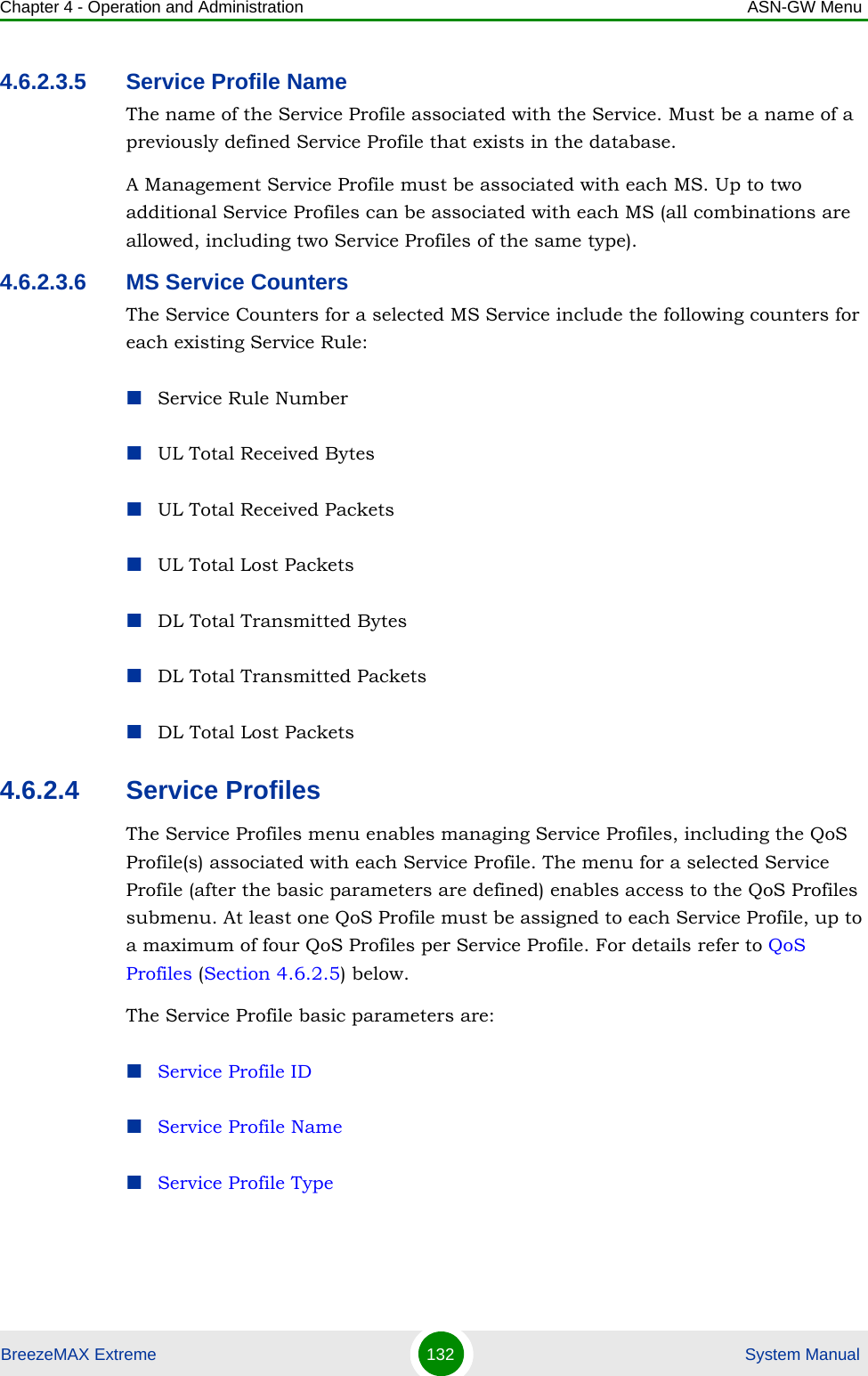
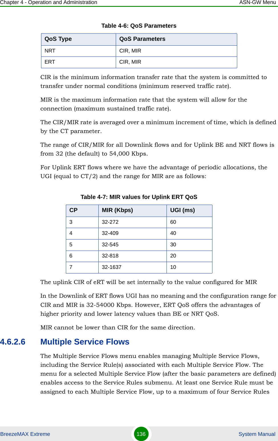
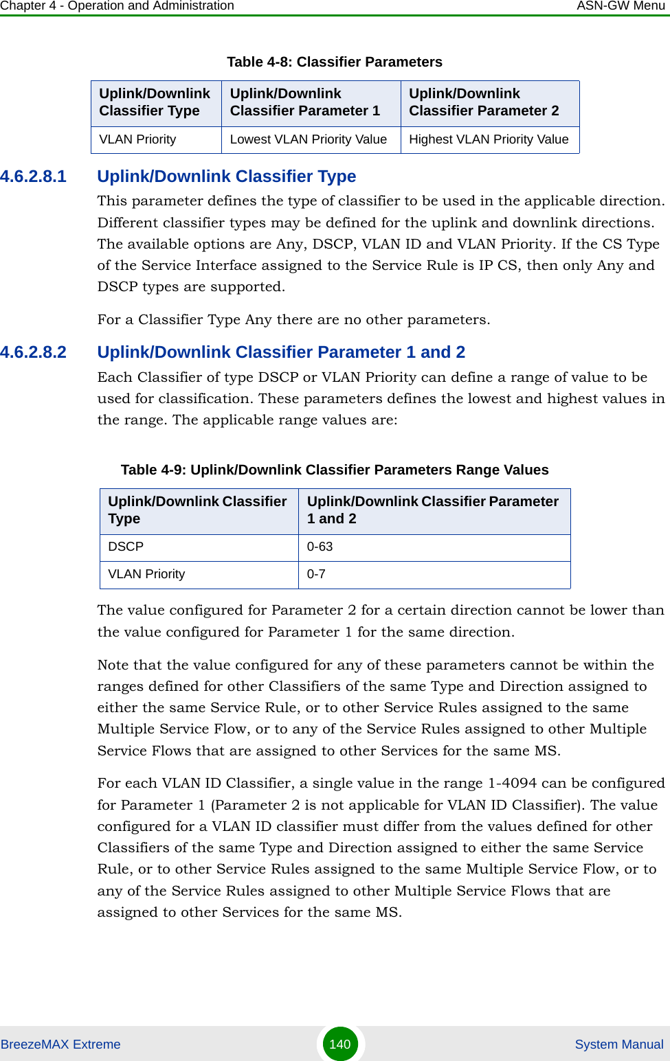
![Chapter 2 - Installation BTS InstallationBreezeMAX Extreme 40 System ManualPlace the tilt bracket on the BTS and fasten its M8 screws (see Figure 2-5 and Figure 2-6). Apply torque of 80 [Lib*In] = 9 [N*m]To assemble the bracket on the BTS:Figure 2-5: Assembling the Tilt Bracket on the BTSTilt bracketBTSM8X20 screwsCarrying grooves](https://usermanual.wiki/Alvarion-Technologies/EXTR-50.Updated-user-manual-Correspondance-39238/User-Guide-1415378-Page-61.png)
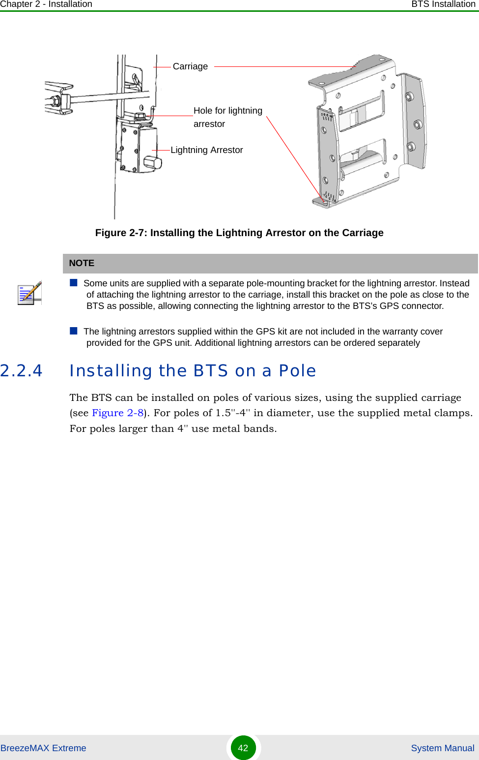
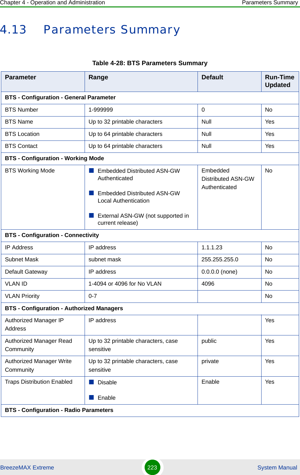
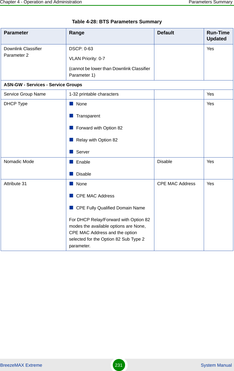
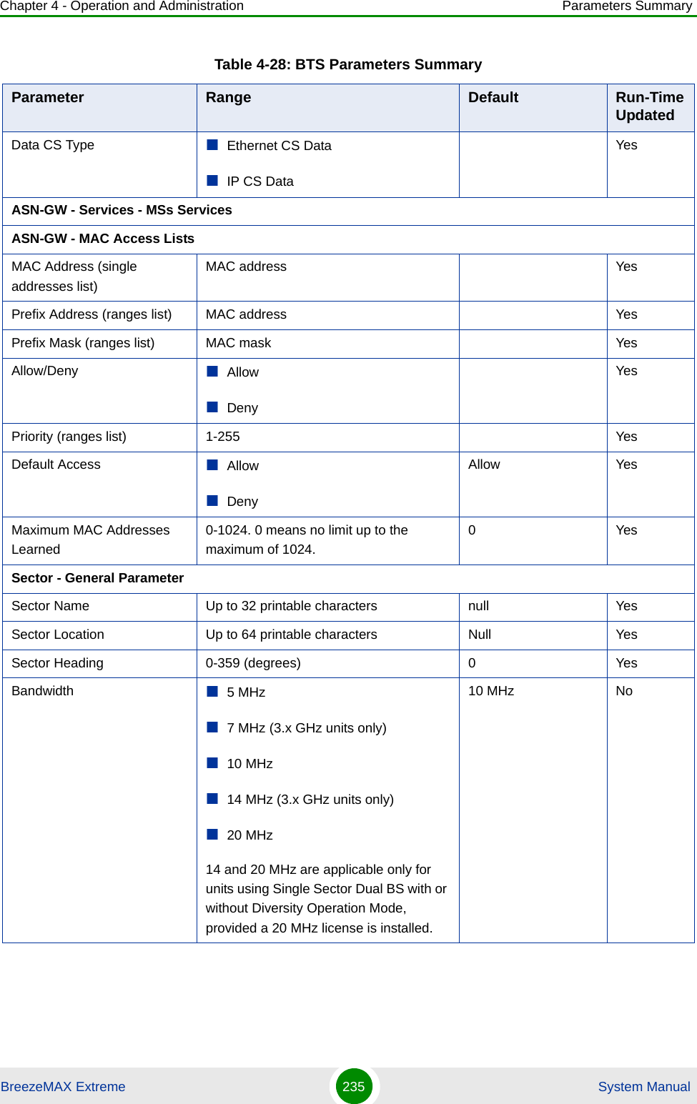
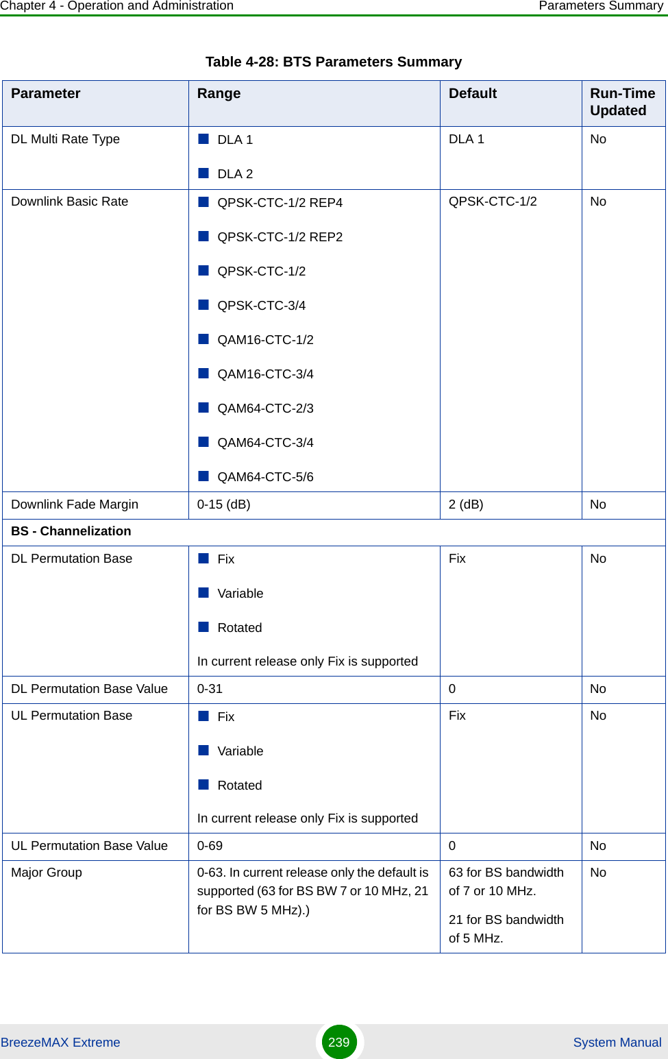
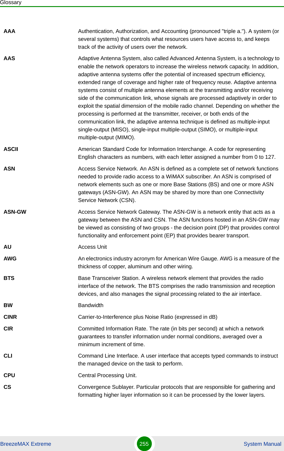
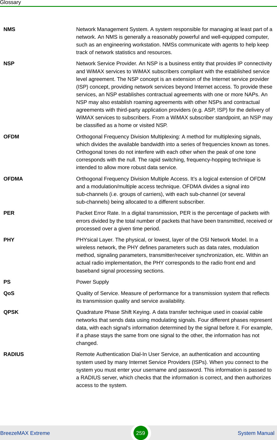
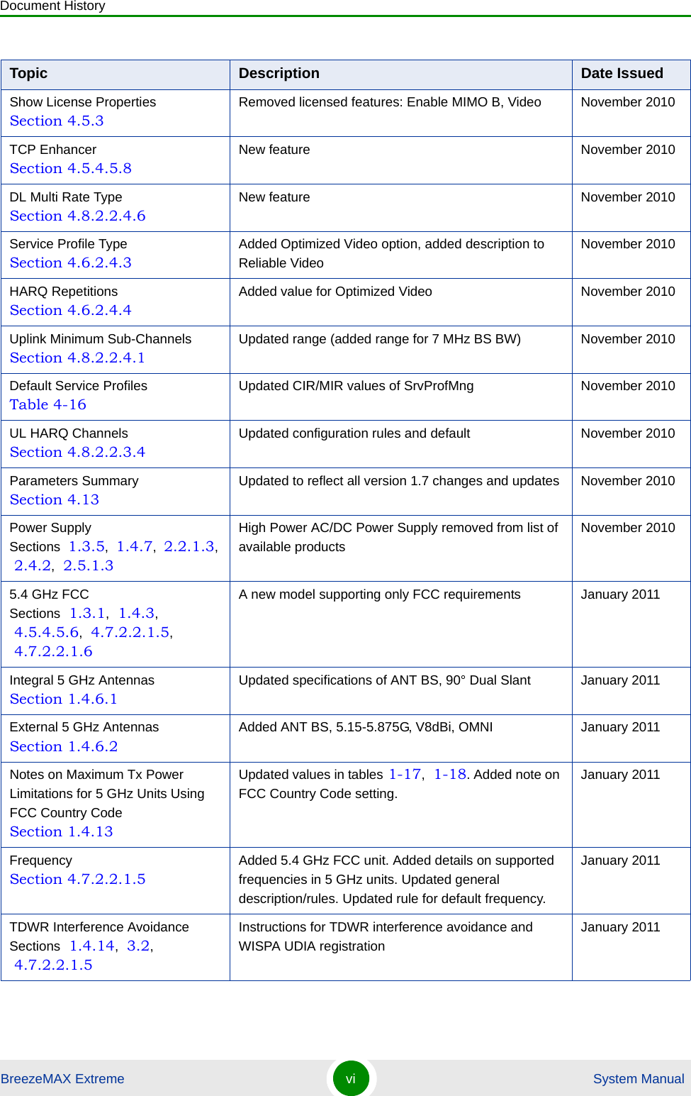
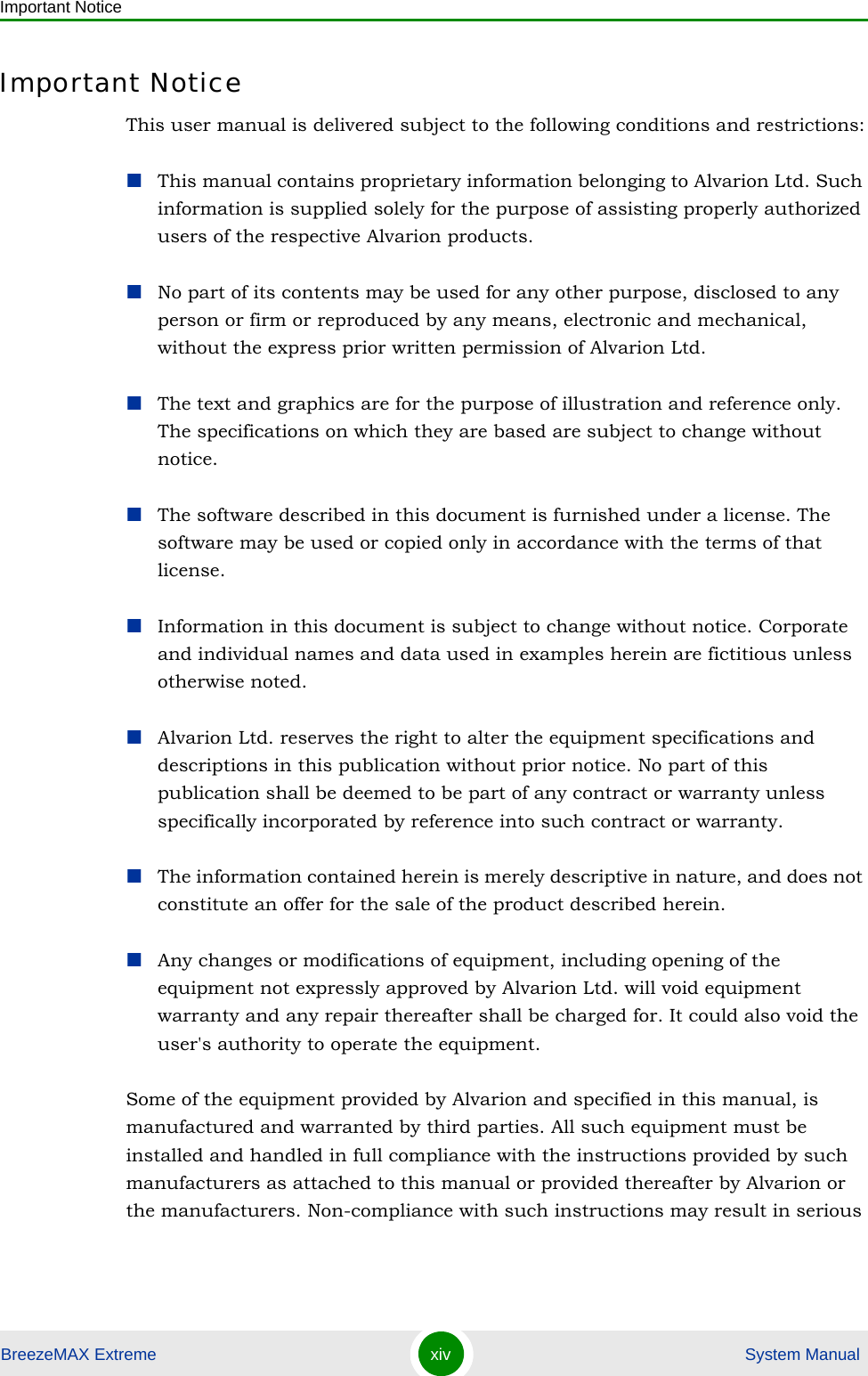
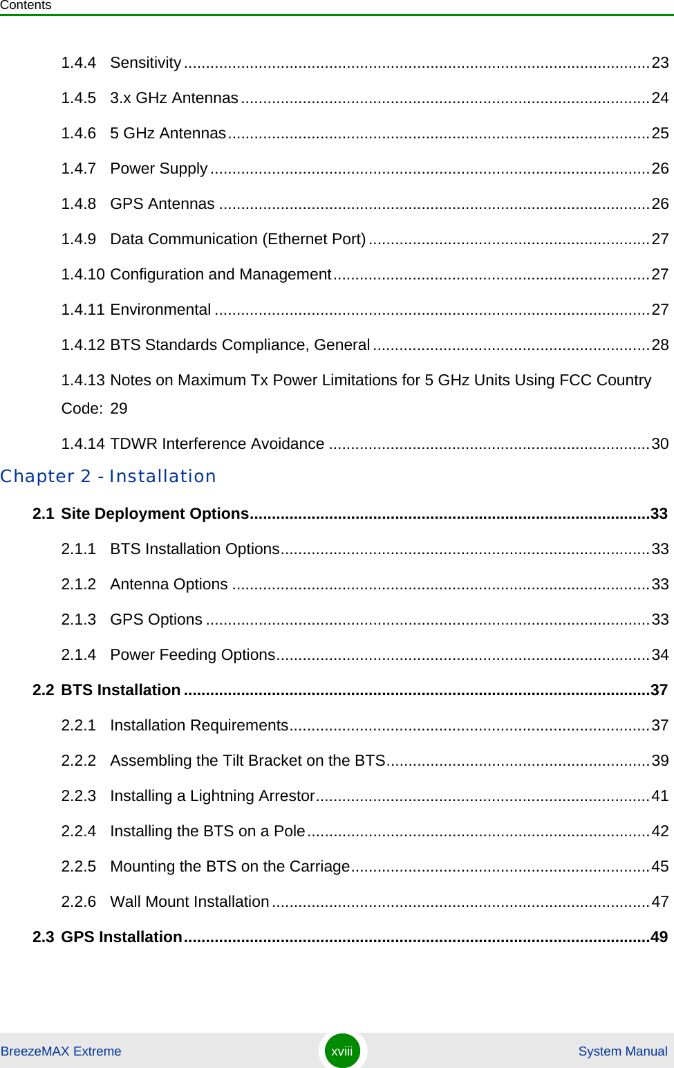
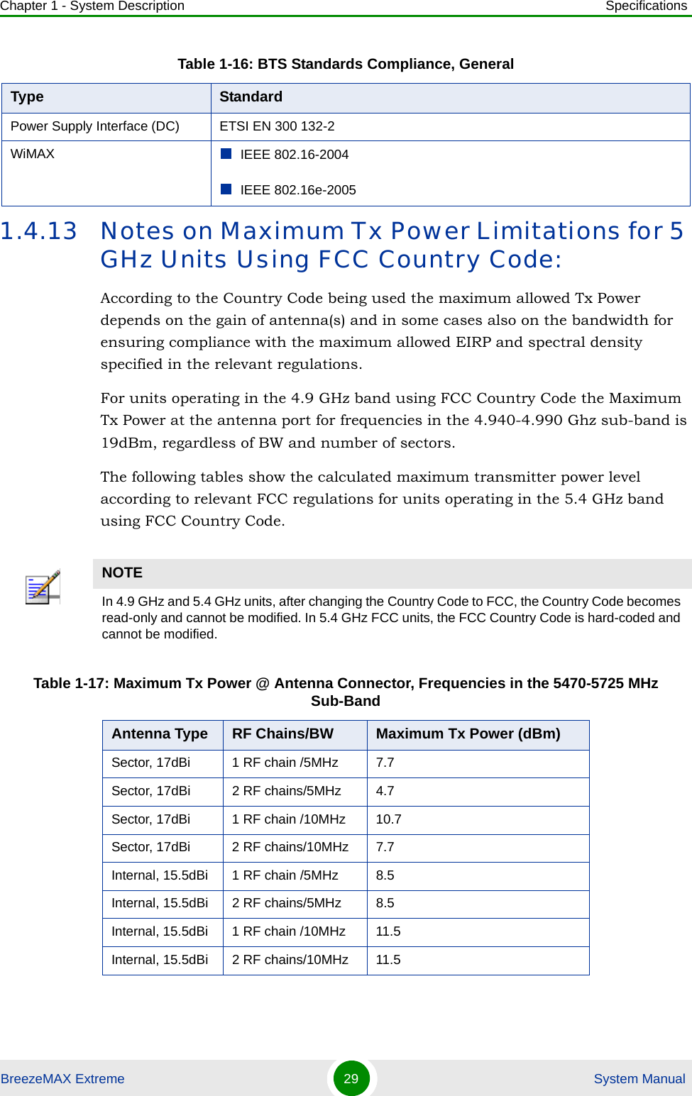
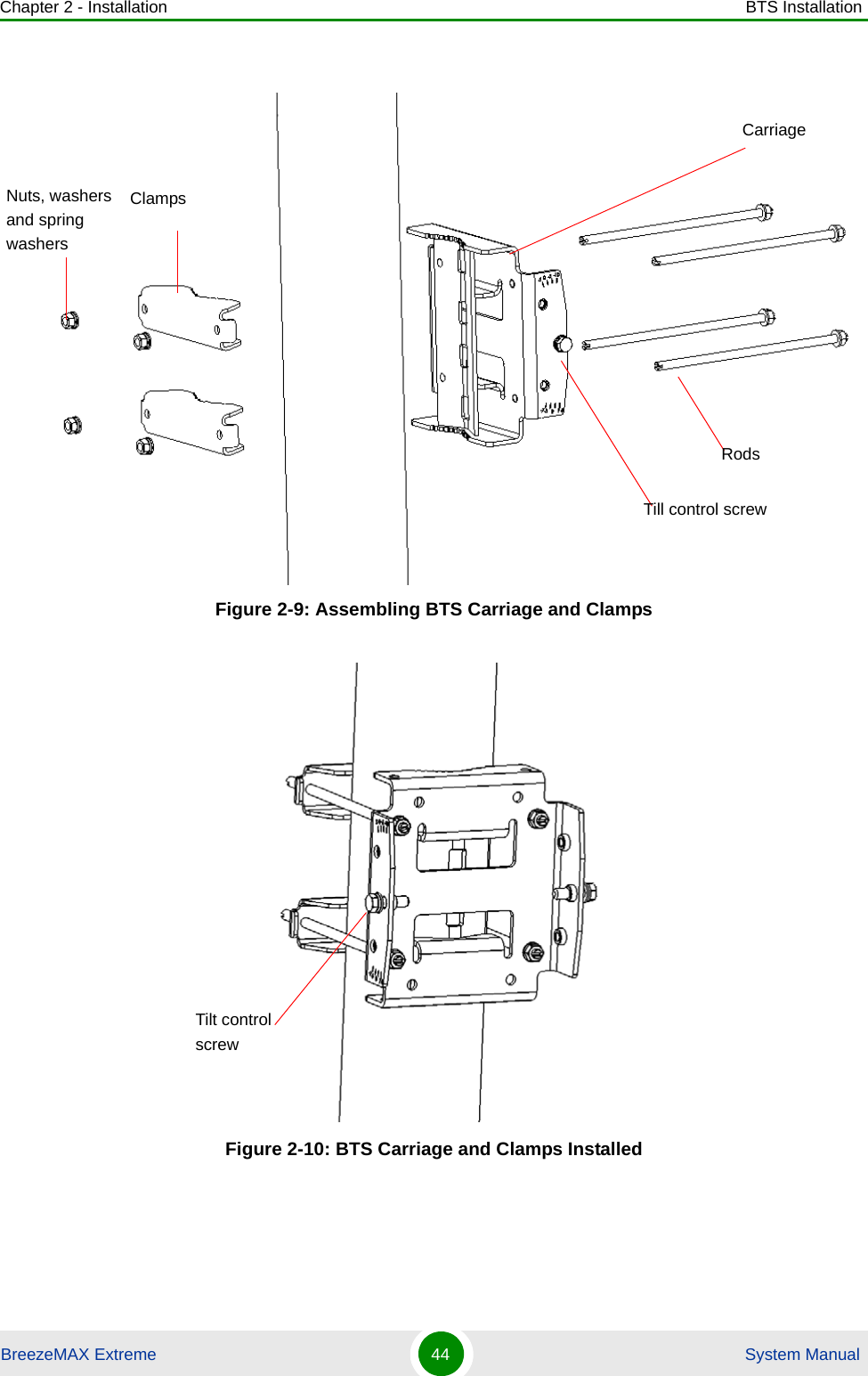
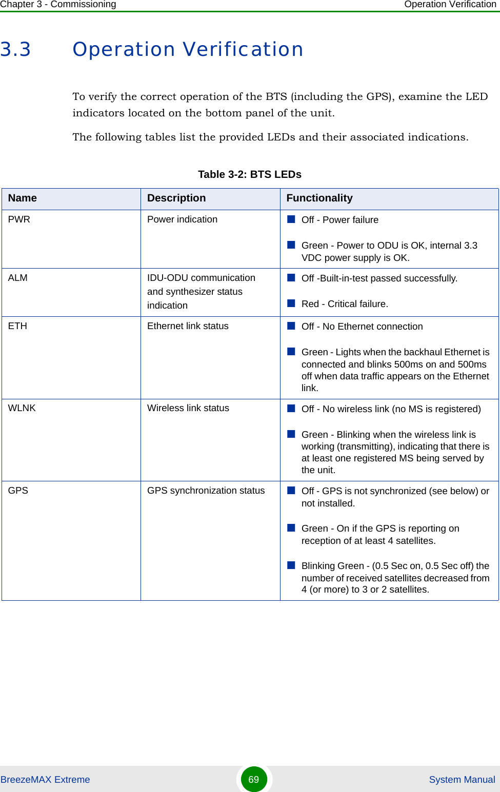
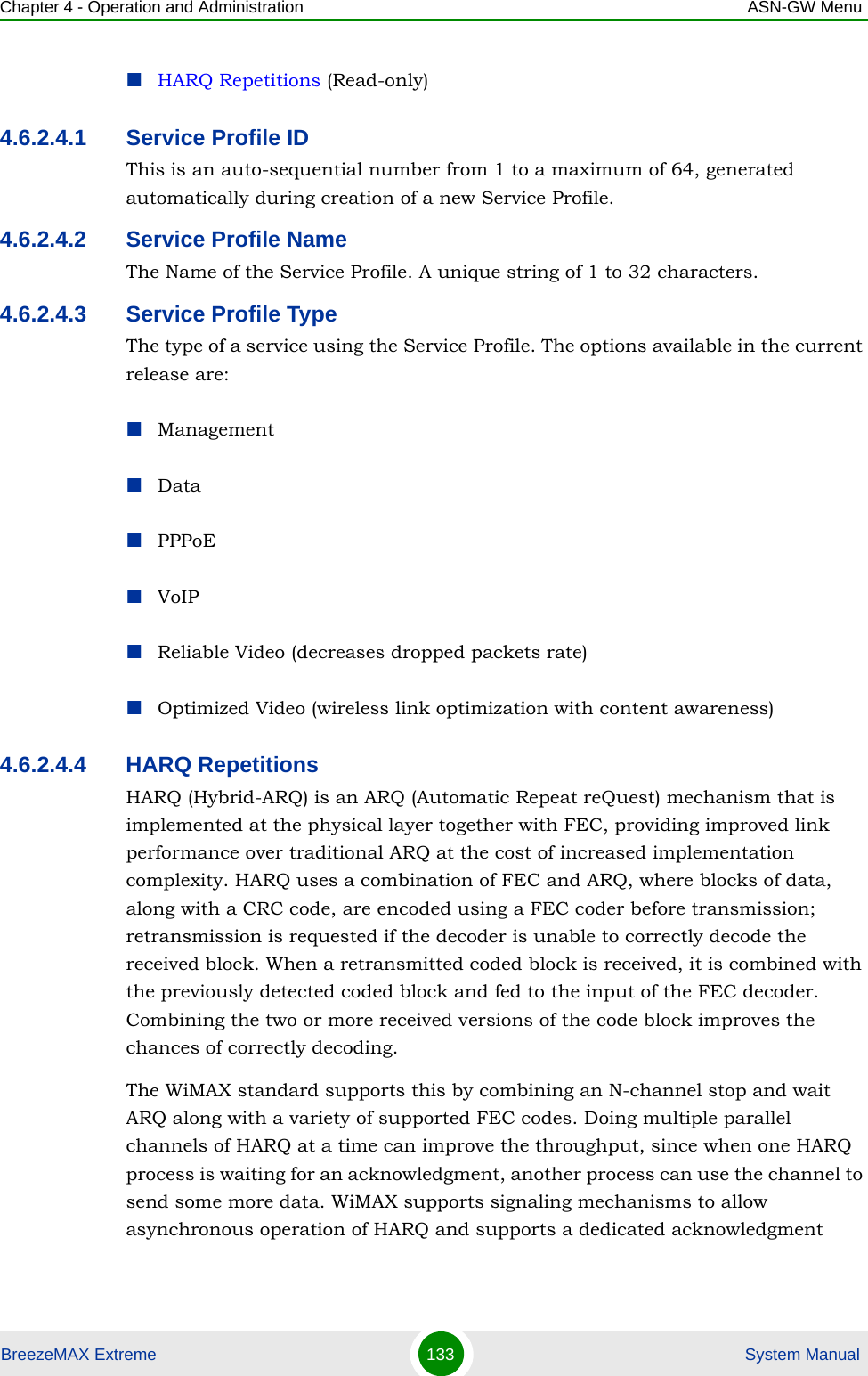
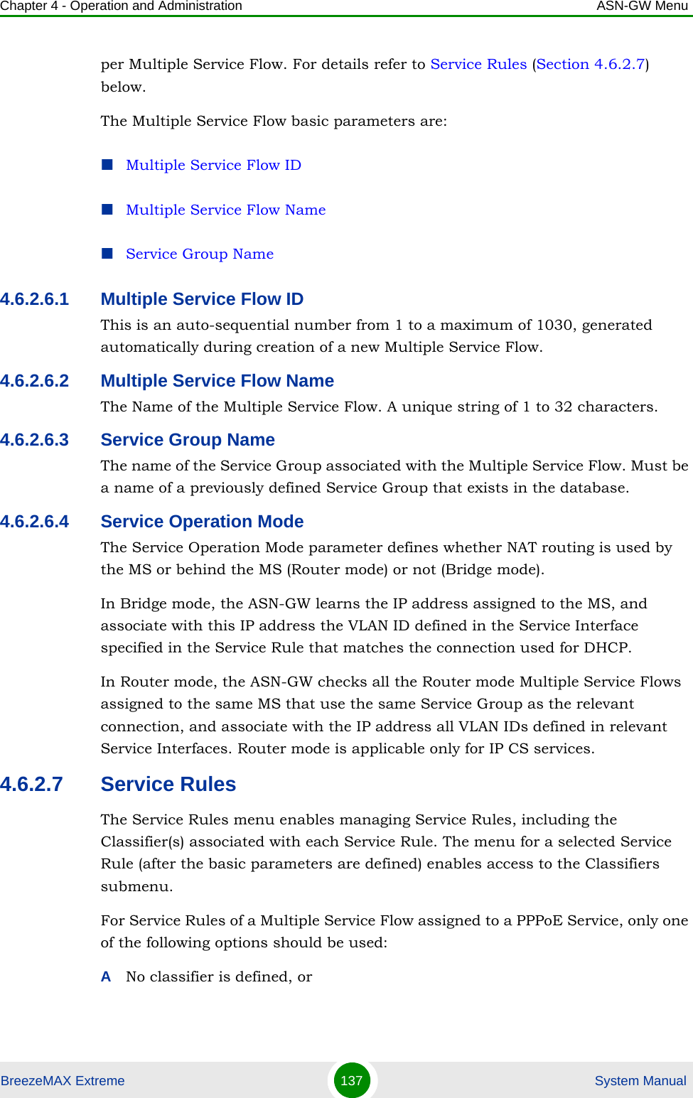
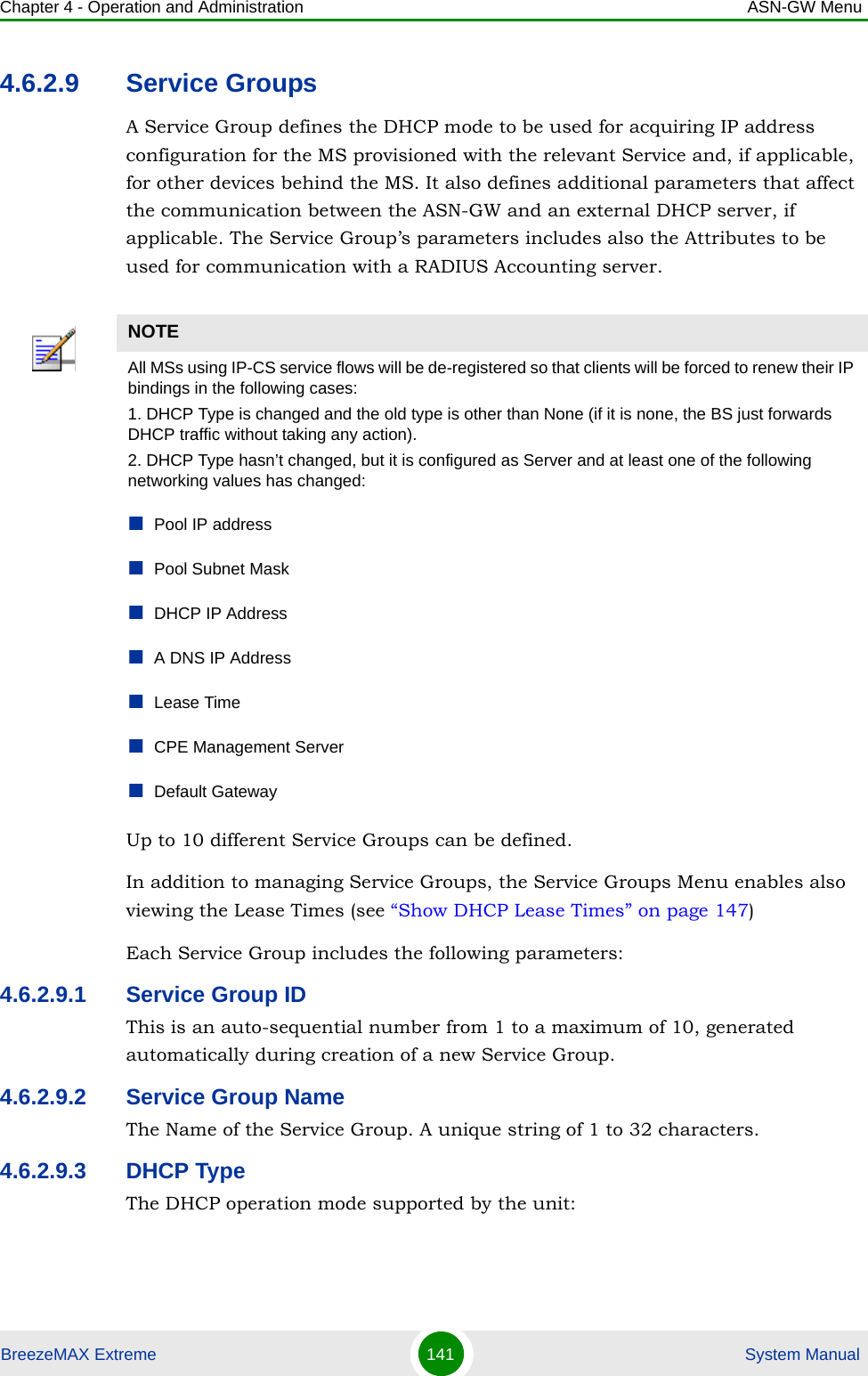
![Chapter 2 - Installation BTS InstallationBreezeMAX Extreme 43 System Manual1Assemble the tilt bracket on the BTS and fasten its four screws (see “Assembling the Tilt Bracket on the BTS” on page 39).2Install a lightning arrestor on the carriage as described in “Installing a Lightning Arrestor” on page 41.3Thread the four rods through the carriage.4Attach the carriage and the clamps to the pole and tighten on both sides using the supplied washers, spring washers and nuts. Apply torque of 80 [Lib*In] = 9 [N*m].5Insert the tilt control screws into the middle-side hole of the carriage on both sides.Figure 2-8: BreezeMAX Extreme Pole Mount CarriageTo install the Carriage on a 1.5''-4'' pole:Holes for pole mounting rods (x4)Holes for wall mounting screws (x4)Groove for metal bandsHoles for fastening screws (x4)Tilt control screws (x2)Holes for lightning arrestor (x4)](https://usermanual.wiki/Alvarion-Technologies/EXTR-50.Updated-user-manual-Correspondance-39238/User-Guide-1415378-Page-64.png)
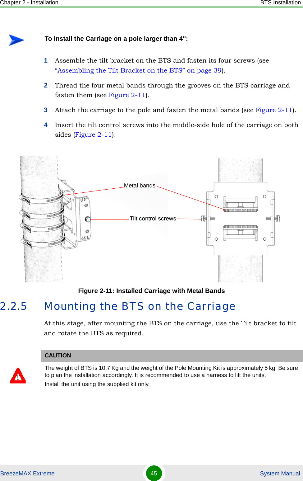
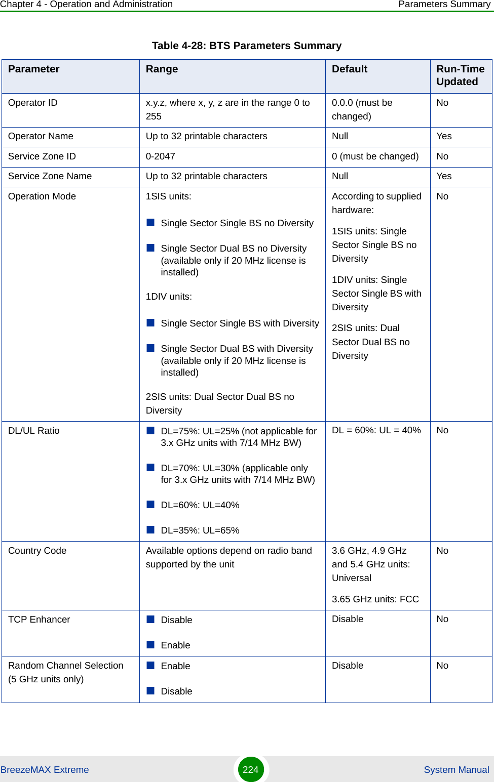
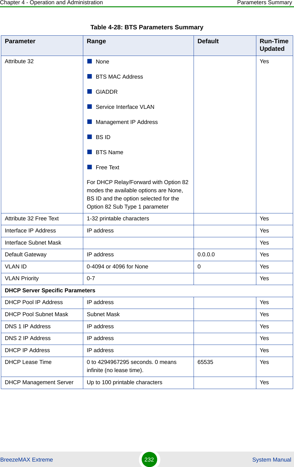
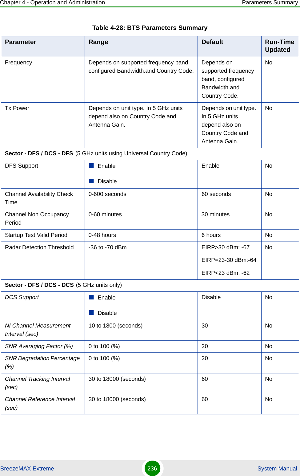
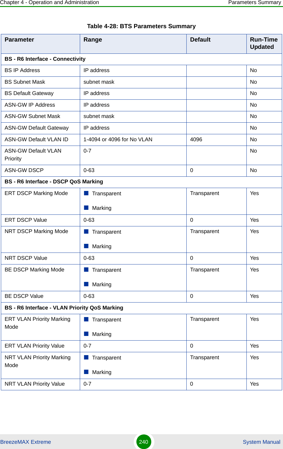
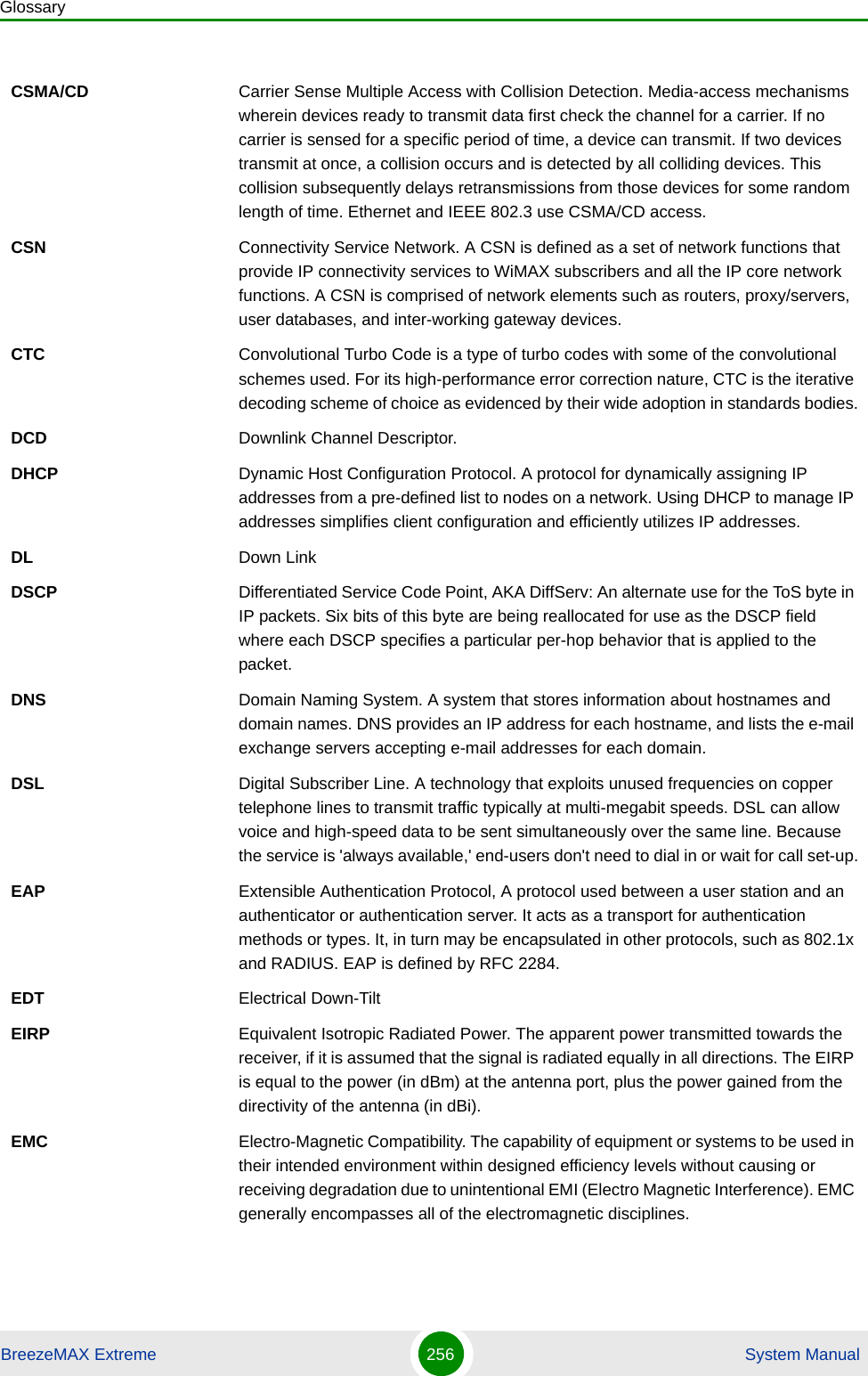
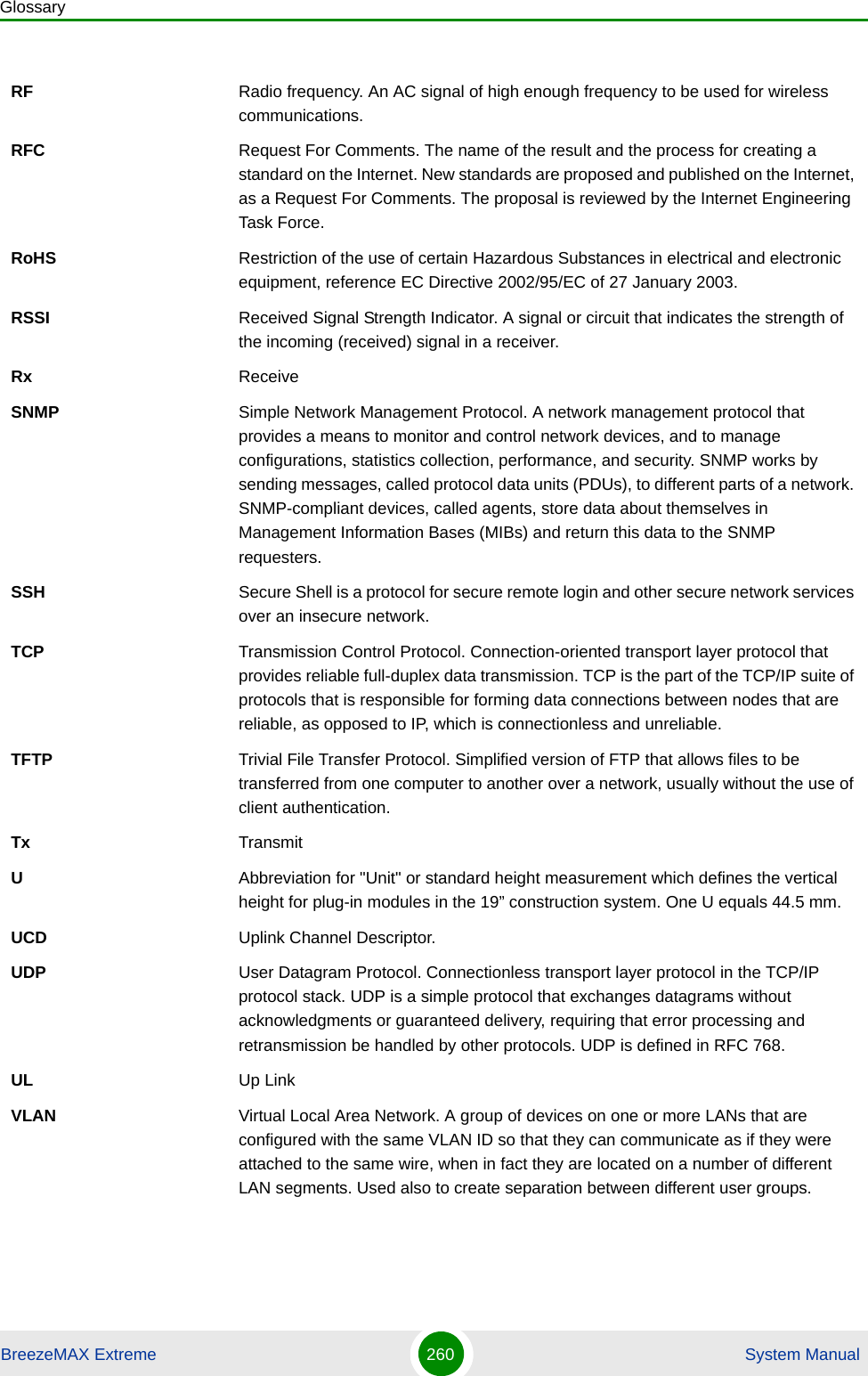
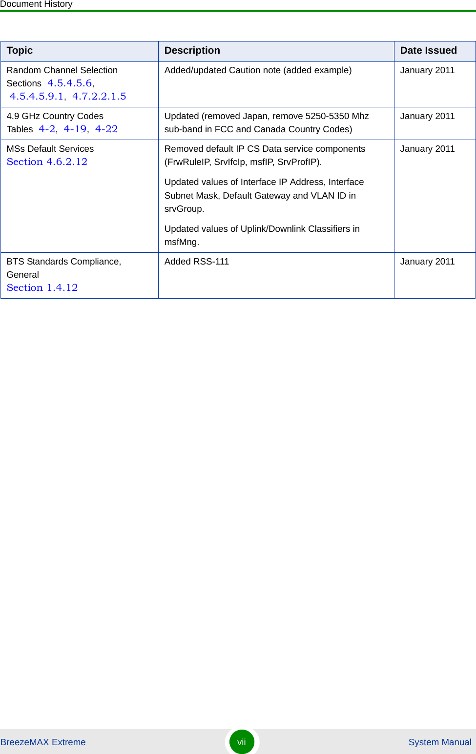
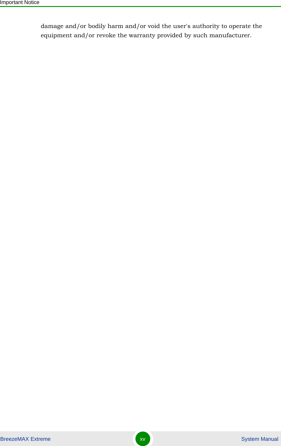
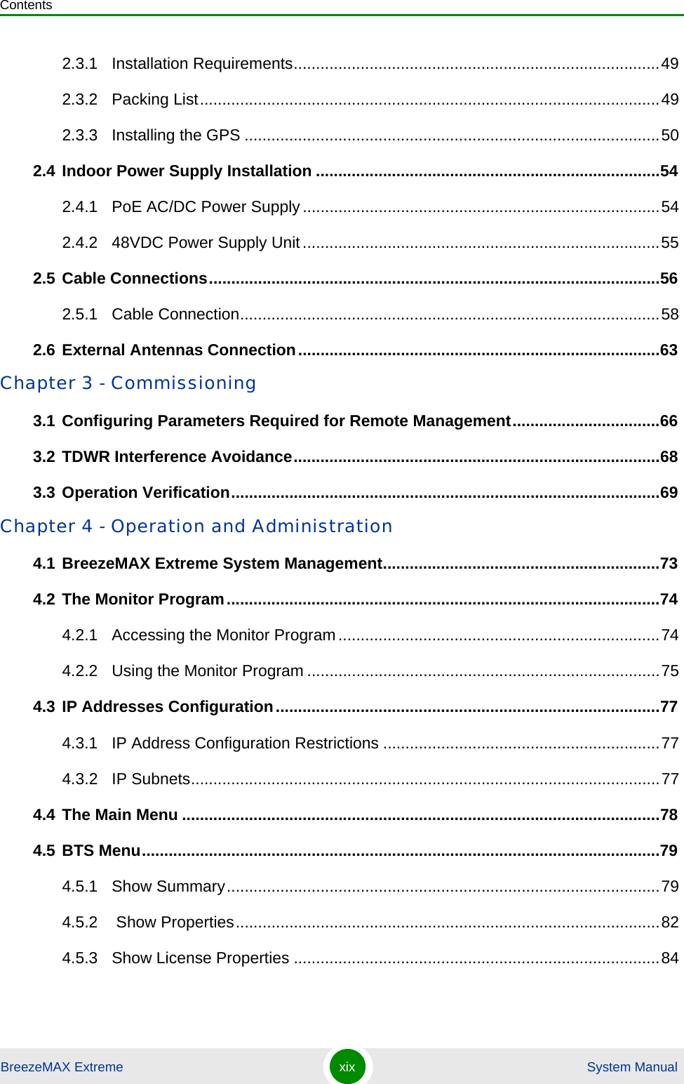
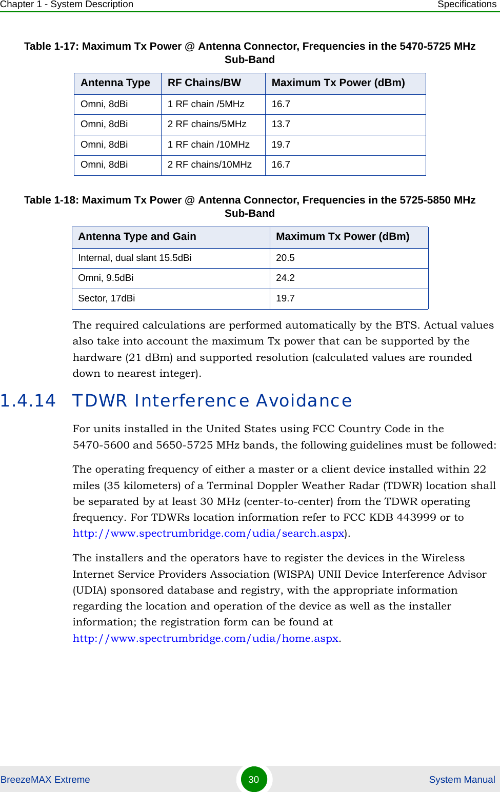
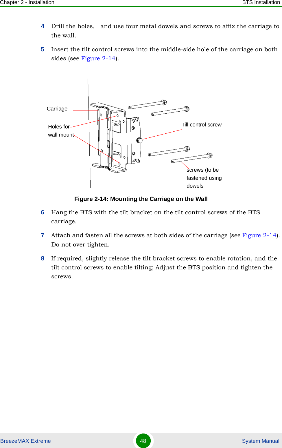
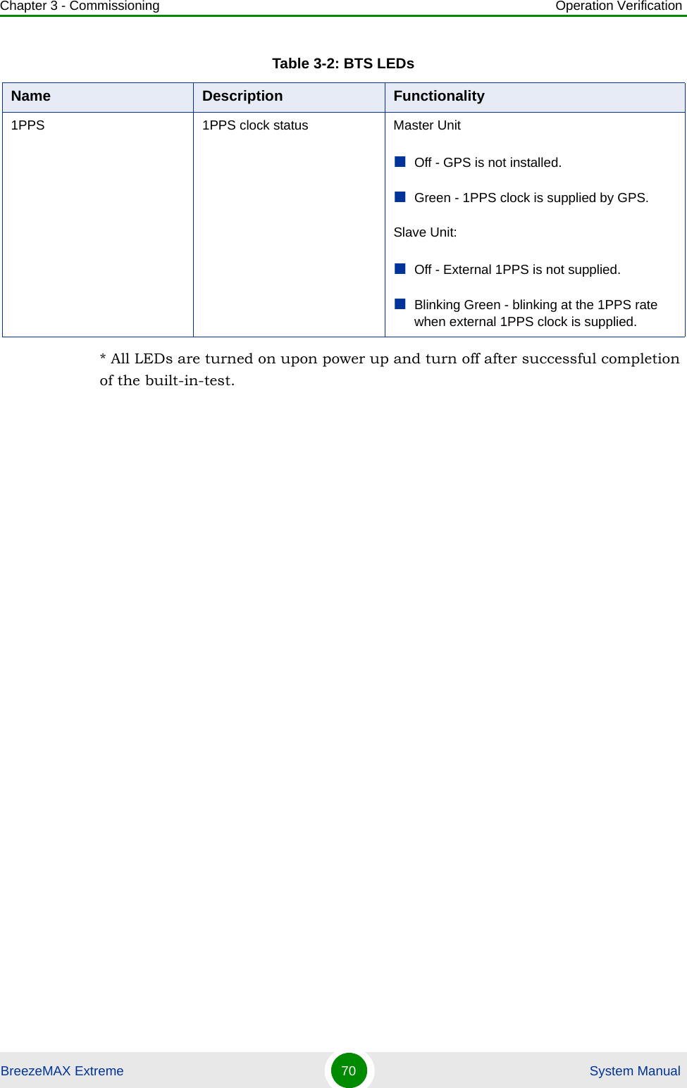
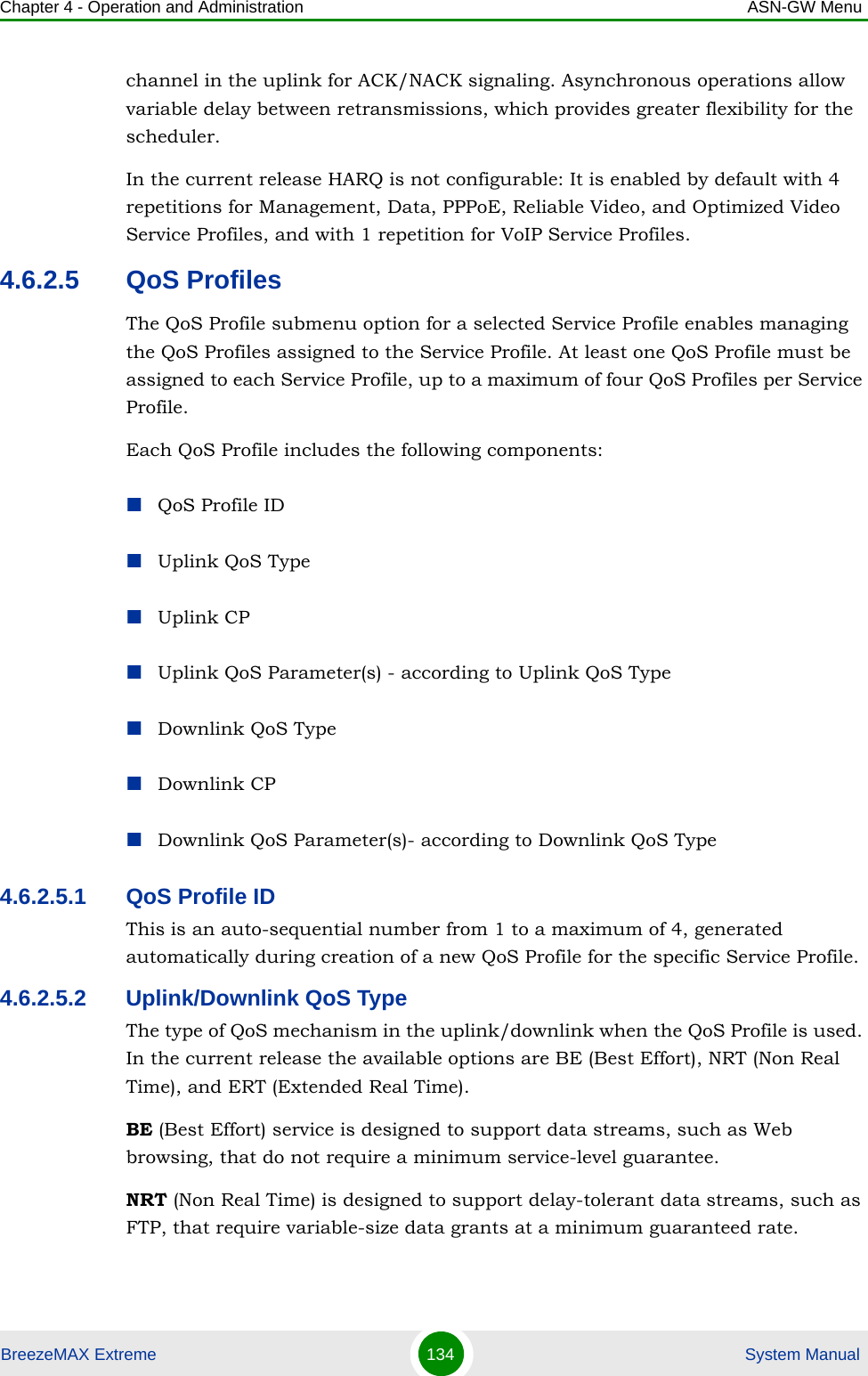
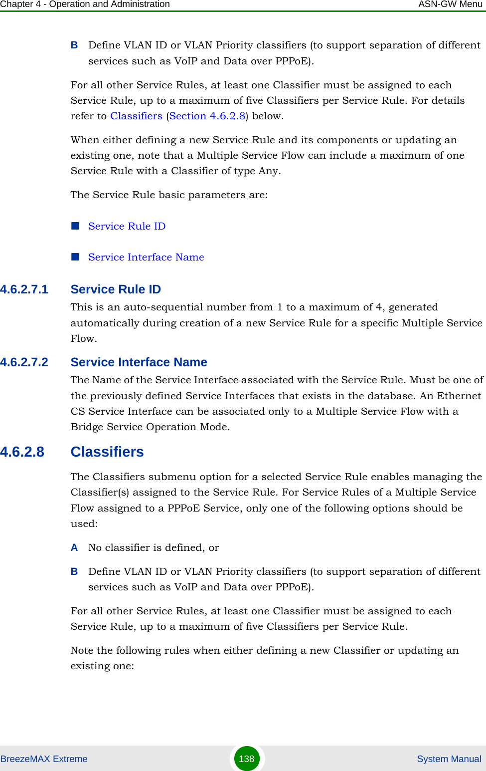
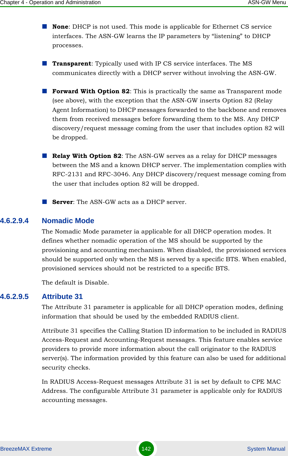
![Chapter 2 - Installation BTS InstallationBreezeMAX Extreme 47 System Manual3If required, slightly release the tilt bracket screws to enable rotation, and the tilt control screws to enable tilting; Adjust the BTS position and tighten the screws. Apply torques of 45 [Lib*In.] = 5 [N*m] to the M6 Tilt-control screws, and 80 [Lib*In] = 9 [N*m] to the M8 screws.2.2.6 Wall Mount InstallationThe BreezeMAX Extreme BTS can be installed on walls or any flat surface. This requires attaching and fastening the carriage with the BTS to the wall using suitable securing means (not supplied) and then tilting and rotating the BTS as required. The location of the screws should be planned with maximum precision.1Assemble the tilt bracket on the BTS and fasten its four screws (see “Assembling the Tilt Bracket on the BTS” on page 39).2If you use a High-Gain GPS antenna with a cable longer than 3m, install a lightning arrestor on the carriage as described in “Installing a Lightning Arrestor” on page 41.3Place the carriage on the wall and mark the exact location of the holes to drill. Figure 2-13: BTS Mounted on a Pole Larger than 4'' (with Metal Bands)To install the BTS on a wall:](https://usermanual.wiki/Alvarion-Technologies/EXTR-50.Updated-user-manual-Correspondance-39238/User-Guide-1415378-Page-68.png)

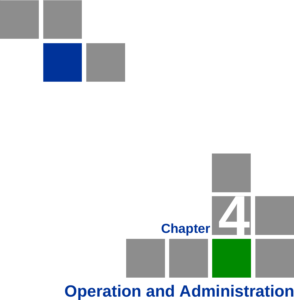
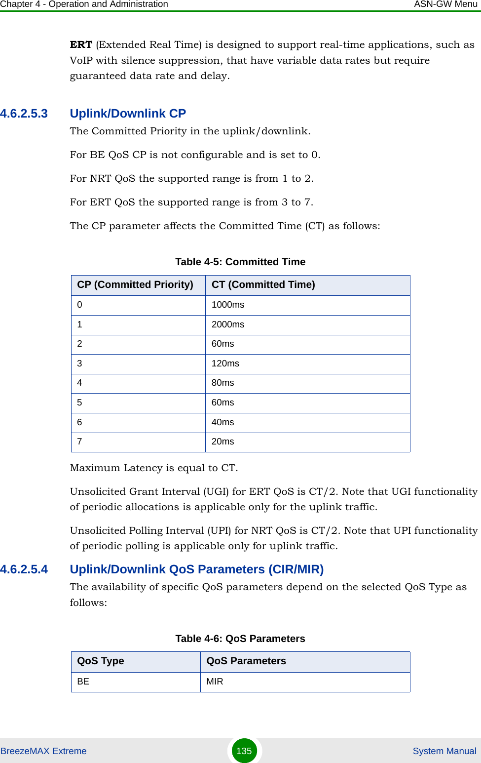
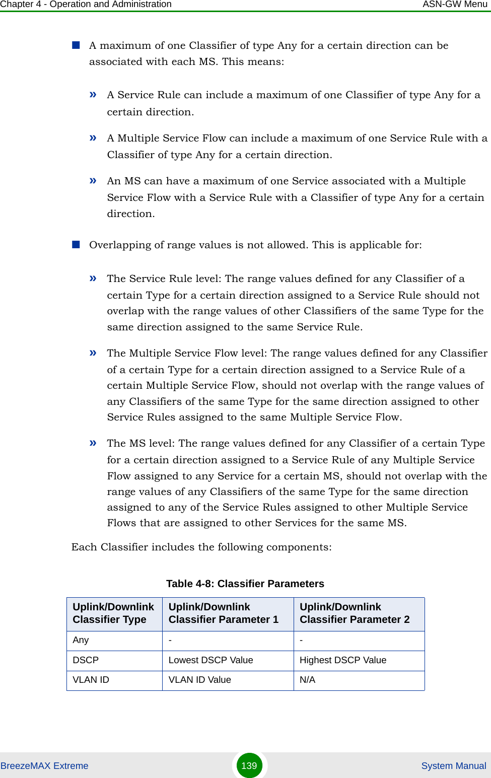
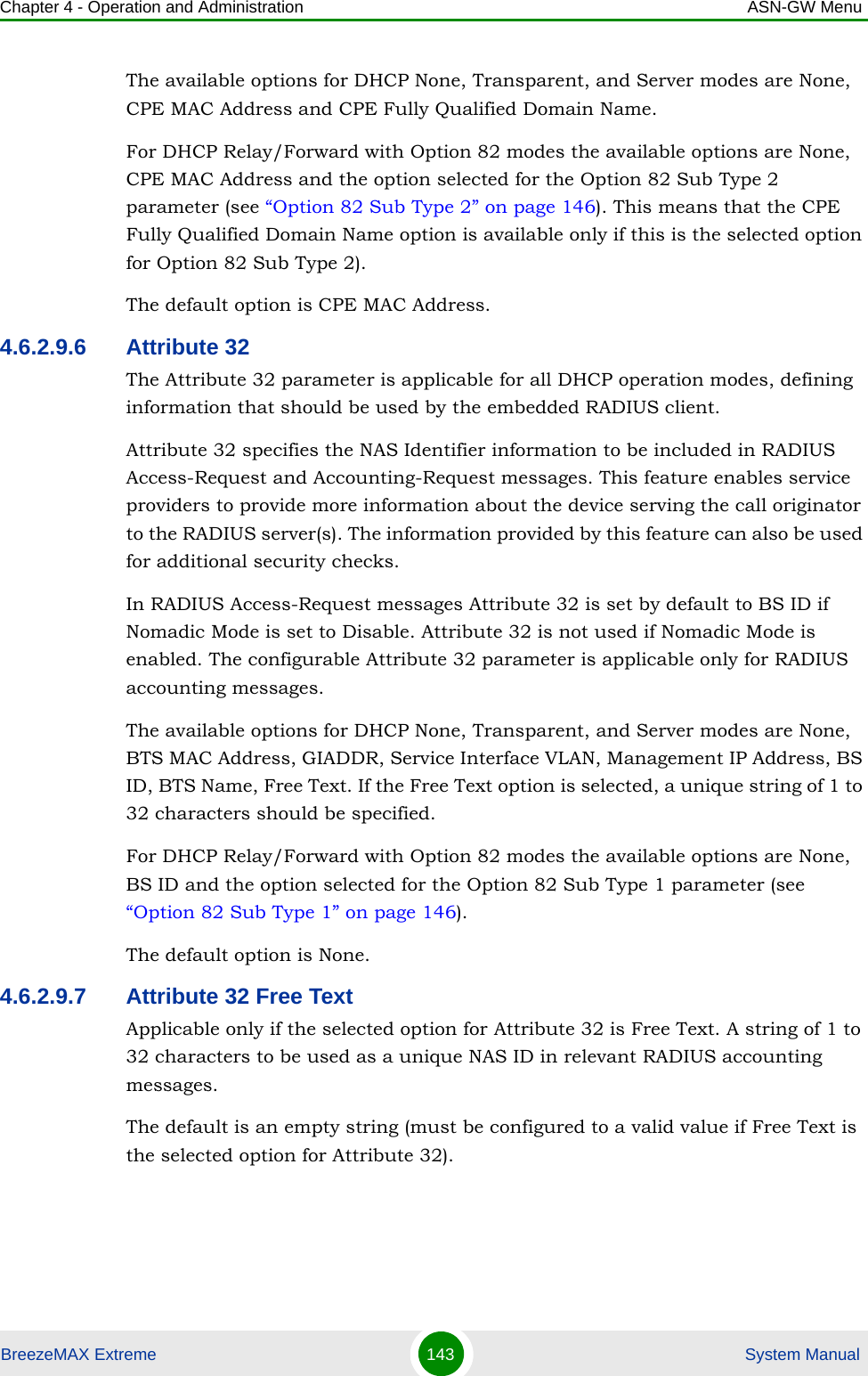
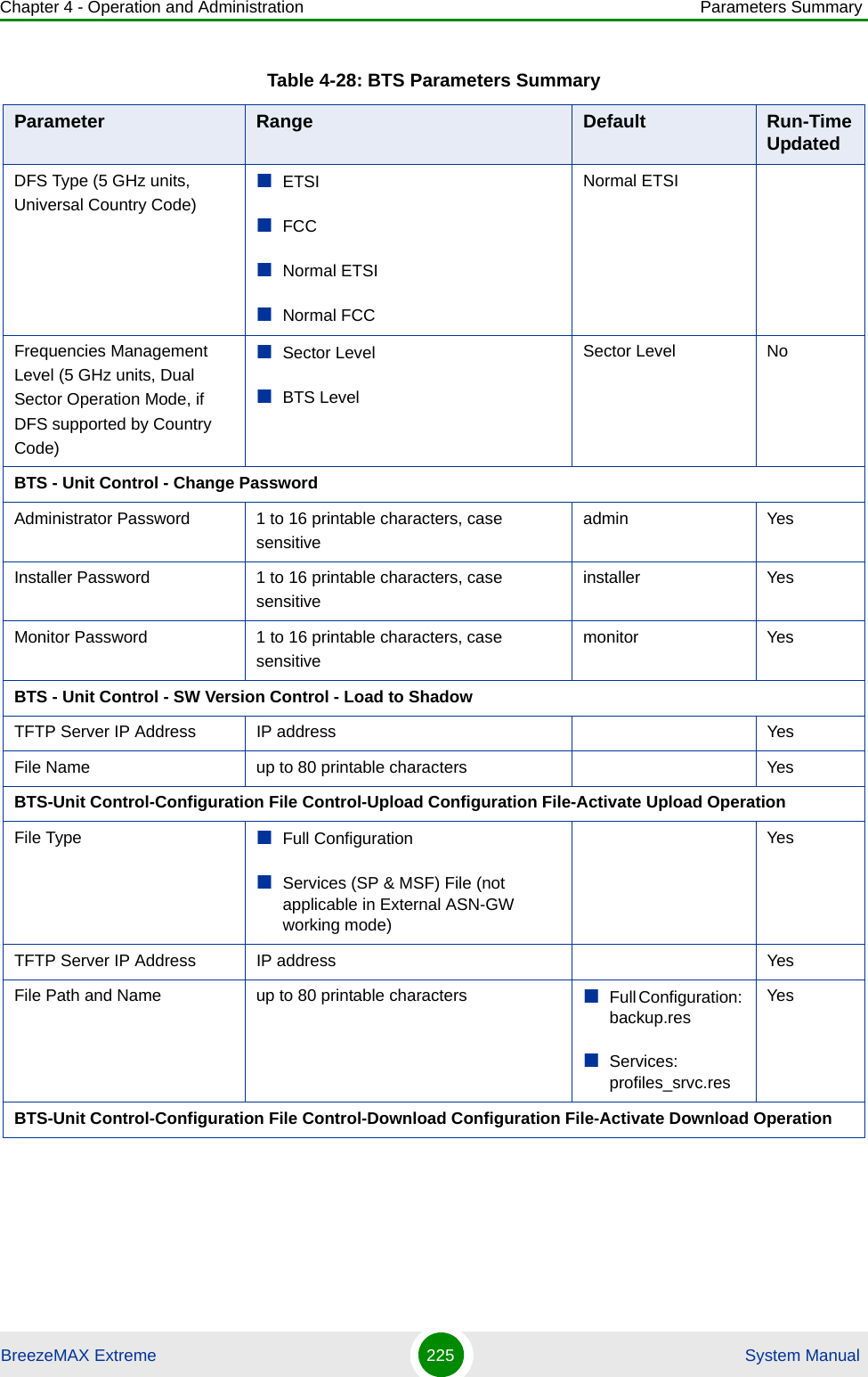
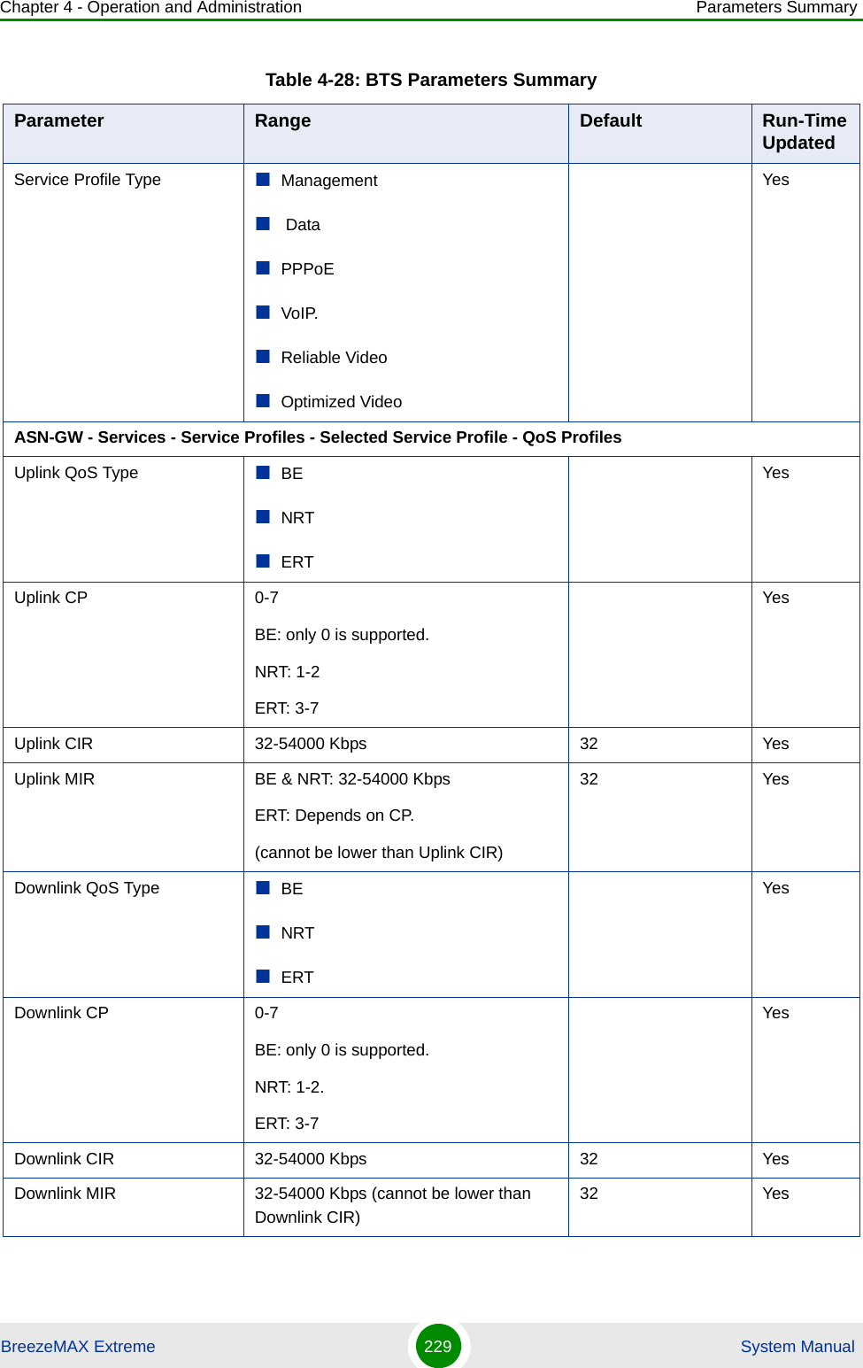
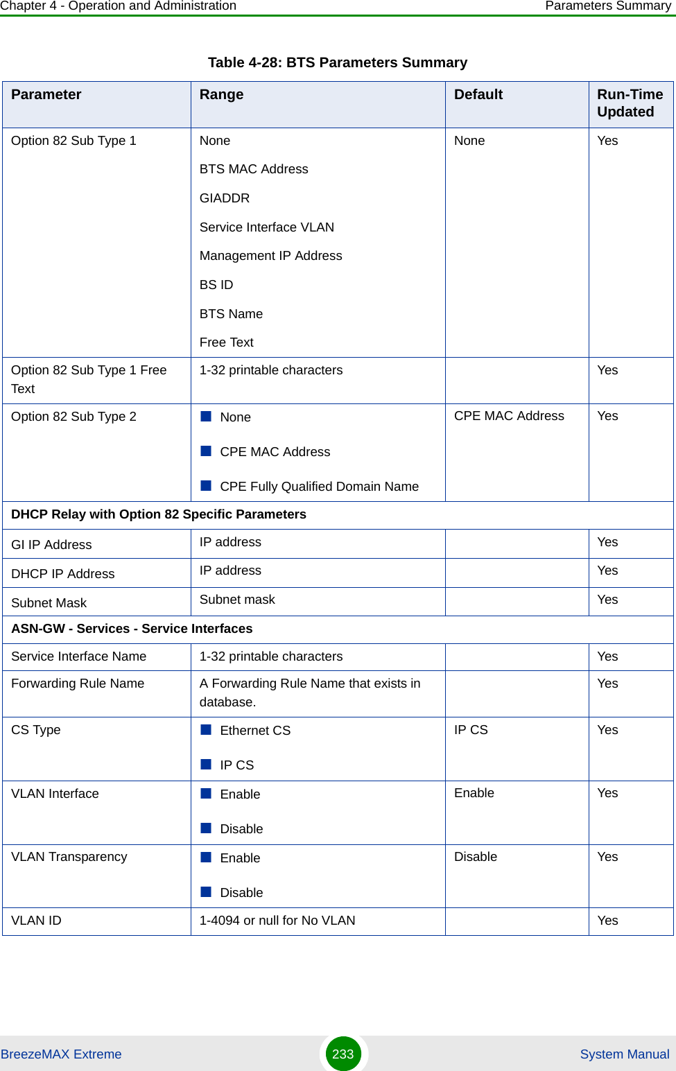
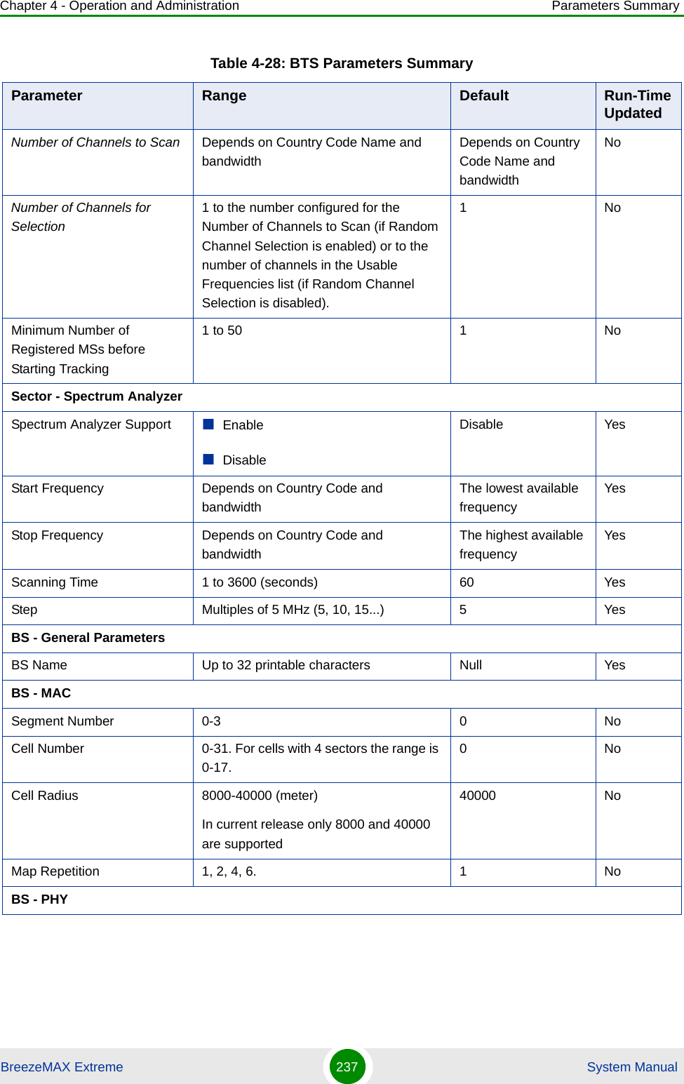
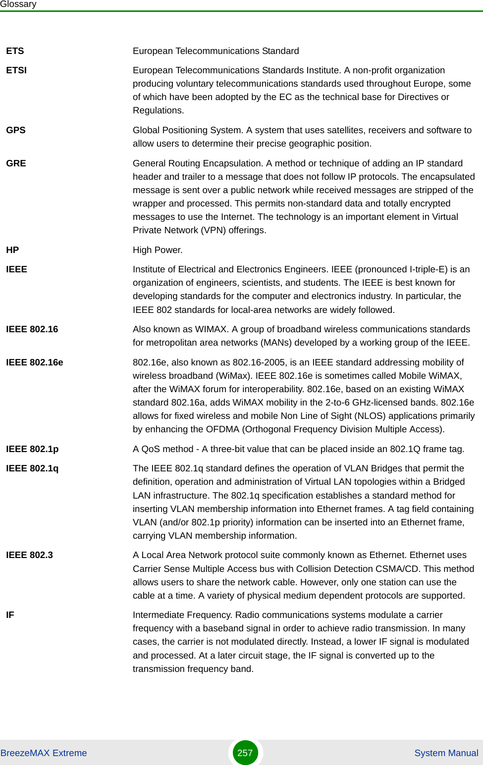
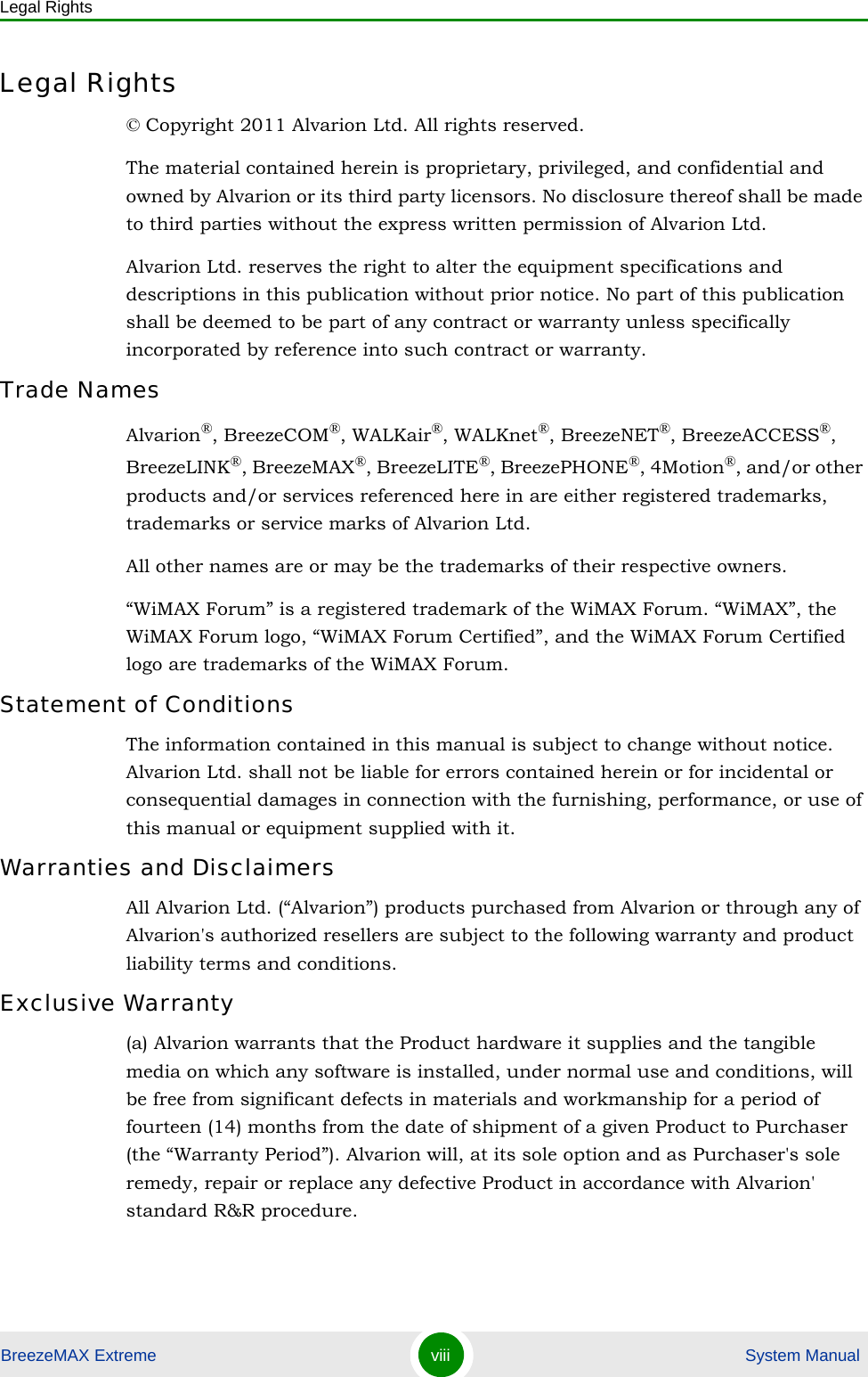
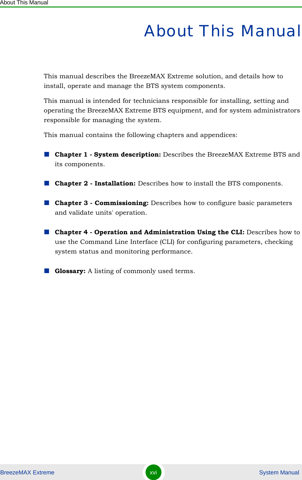
![Chapter 4 - Operation and Administration ASN-GW MenuBreezeMAX Extreme 152 System ManualCIR is the minimum information transfer rate that the system is committed to transfer under normal conditions (minimum reserved traffic rate). MIR is the maximum information rate that the system will allow (maximum sustained traffic rate). The CIR/MIR rate is averaged over a minimum increment of time, which is defined by the CT parameter.The range is from 32 (the default) to 54,000 Kbps.MIR cannot be lower than CIR.4.6.2.12 MSs Default ServicesThe BTS is supplied with a set of default service components supporting typical Management and Ethernet CS Data services. The default service components cannot be deleted. However, they may be updated.The default service components are:NRT CIR, MIRTable 4-12: Default Forwarding RulesForwarding Rule Name [[FrwRuleEth]]Relay Mode EnableUnknown Address Forwarding Mode ForwardQoS Type BECP 0MIR (kbps) 512Table 4-13: Default Service InterfacesService Interface Name [[SrvIfcEth]]Forwarding Rule Name [[FrwRuleEth]]CS Type Ethernet CSInner DSCP Marking DisableVLAN Interfaces EnableVLAN Transparency DisableTable 4-11: QoS ParametersQoS Type QoS Parameters](https://usermanual.wiki/Alvarion-Technologies/EXTR-50.Updated-user-manual-Correspondance-39238/User-Guide-1415378-Page-173.png)
![Chapter 4 - Operation and Administration ASN-GW MenuBreezeMAX Extreme 153 System ManualVLAN ID 1234VLAN Priority Marking EnableVLAN Priority 0Table 4-14: Default Service GroupService Group Name [[srvGroup]]DHCP Type TransparentNomadic Mode DisableAAA Attribute 31 NoneAAA Attribute 32 NoneInterface IP Address Management Interface IPInterface Subnet Mask Management Interface Subnet MaskDefault Gateway Management Interface GatewayVLAN ID Management VLANTable 4-15: Default Multiple Service FlowsMultiple Service Flow Name [[msfMng]] [[msfEth]]Service Group Name [[srvGroup]] [[srvGroup]]Service Operation Mode Bridge RouterService Rule ID 1 1Service Interface Name [[SrvIfcIp]] [[SrvIfcEth]]Classifier ID 1 1Uplink Classifier Type DSCP DSCPUplink Classifier Parameter 1 6 0Uplink Classifier Parameter 2 6 0Downlink Classifier Type DSCP DSCPDownlink Classifier Parameter 1 6 0Downlink Classifier Parameter 2 6 0Table 4-16: Default Service ProfilesService Profile Name [[SrvProfMng]] [[SrvProfEth]]Service Profile Type Management DataTable 4-13: Default Service Interfaces](https://usermanual.wiki/Alvarion-Technologies/EXTR-50.Updated-user-manual-Correspondance-39238/User-Guide-1415378-Page-174.png)