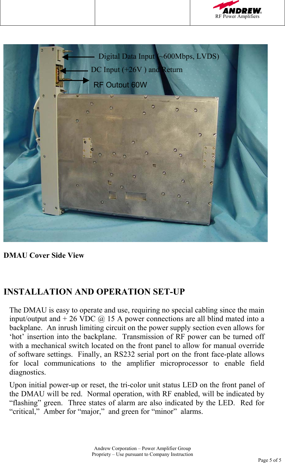
Andrew Base Station Subsystems Group 100154DMAU-U Digital Multi-Carrier Amplifier User Manual VJD U manual

Andrew Corporation, Base Station Subsystems Group Digital Multi-Carrier Amplifier VJD U manual

Users Manual

   RF Power Amplifiers   Andrew Corporation – Power Amplifier Group Propriety – Use pursuant to Company Instruction     Page 1 of 1            Digital Multi-Carrier Amplifier  Model : DMAU-U   Operation Instruction         Date: June 17, 2005 Ver. 1.0A  Ref#  FCC ID: S8L-100154DMAU-U
   RF Power Amplifiers   Andrew Corporation – Power Amplifier Group Propriety – Use pursuant to Company Instruction     Page 2 of 2  Introduction This document presents a description of the Andrew Digital Multi-carrier Amplifier Unit (DMAU).  The DMAU is a 60 Watt (RF), high efficiency base-station amplifier.  It accepts as input a digital representation of multiple CDMA carriers and produces a multi-carrier RF signal at its output.  The amplifier transmits RF power over a 20MHz instantaneous bandwidth within the US PCS frequency band of 1930MHz to 1990MHz.  Up to 15 CDMA2000 carriers or 4 WCDMA carriers can be transmitted by the DMAU within the instantaneous bandwidth.   Since the DMAU has been designed for cellular base-station use, it satisfies all relevant transmission requirements, such as spectral mask limits and emission limits called for by the 3GPP2 and 3GPP standards.  At rated power and multiple carrier operation, the in band transmit port emissions are below –13dBm/1MHz for all carrier combinations and counts.     DMAU Specifications Table 1 below highlights some of the key design specifications that the DMAU satisfies.    Table 1:  Key DMAU Specifications 1)  Input Signal:  Multi-Carrier CDMA2000 or WCDMA (Channel Occupied Bandwidth: CDMA2000-1.25MHz, WCDMA-4.21MHz) presented as digital data. 2)  Input Signal Format: Multi-Carrier Digital Baseband (Separate I and Q signals over 600Msps LVDS) 3)  Overall DC-to-RF efficiency: 14%  at 26VDC input and 60WRF output 4)  Output Power: 60 Watts total average power. 5)  Nominal Input Voltage:   +26VDC    (+36VDC max for no failure, transmission stops at 32VDC) 6)  System Communication Port: 100-base-T Ethernet 7)  Operating Temperature Range:  -40°C to +55°C 8)  Weight: 9Kg;  Dimension: 41.51mm(W) x 461mm(D) x 458.83mm(H) 9)  Environmental:   Sealed for Outdoor Air Cooling   DMAU Interface There are a total of six external interfaces to the DMAU.  A description of each interface is provided below.    1)  Digital Input Port – Accepts Digital data stream representing multiple carriers of CDMA2000 or WCDMA.   2)  RF Output Port – Main RF output. 60W average power is delivered across 1 to 15 CDMA2000 carriers or 1 to 4 UMTS carriers. 3)  Front Panel Debug Port –  RS232 port used for craft access. 4)  DC Input Port –  +26VDC input port with approximately 16ADC current draw at rated power.   5)  Transmit On/Off Switch – A mechanical reset switch used to turn off transmit power(not DC), or to force DMAU into software reset. Located on the front panel.
   RF Power Amplifiers   Andrew Corporation – Power Amplifier Group Propriety – Use pursuant to Company Instruction     Page 3 of 3 6) Tri-Color LED – Single LED that illuminates in green, amber, or red depending on operating condition.  This interface is located on the front panel.   DMAU Circuit Board/Module Functional Descriptions DMAU contains three individual printed circuit boards and two sub-circuit modules.  The main transmit path  flows through all three circuit boards.  A description of these boards and their functions follows.    1)  Power Supply Board (RF500501):  The power supply board contains the power converter module and other DC-DC converter circuits needed to convert in-coming 26Vdc to 28Vdc, 7.0Vdc, and 3.3Vdc for use by the internal DMAU circuits. Inrush current limiting circuits, input and output filtering circuits, and fuse protection circuits are also included on the PSB.  2)  Power Converter Module (RF500480):  Converter module used to convert the incoming +26VDC input which is allowed to vary over some limited range and produce a steady, regulated +28VDC output for use by the other DMAU circuits.  This module is assembled onto the Power Supply Board.  3)  Signal Processing Board (RF500512):  This board contains the main digital control micro-processor which runs the software needed to control and monitor various DMAU hardware functions.  The micro-processor also allows communication with the DMAU is enabled through a RS232 communication port on the front panel.  The SPB also holds the Digital-to-Analog Converter (DAC), which creates the analog output which is then amplified through the RF Amplifier Board.  4)  RF Amplifier Board (RF500475):  The RF Amplifier Board raises the level of the SPB signal to the rated DMAU output power through a chain of gain stages.  A circulator(off board) is included at the end of the transmit path to protect the RF power stages from reverse power flow.   5) Amplifier Module(RF500475):  The Amplifier Module is an impedance matched RF power transistor used multiple times in the Amplifier board to attain the rated RF power of 60W at the output of the DMAU.
   RF Power Amplifiers   Andrew Corporation – Power Amplifier Group Propriety – Use pursuant to Company Instruction     Page 4 of 4 DMAU Photographs    DMAU Front View    Debug Port Tx Enable/DisableSwitch LED indicator
   RF Power Amplifiers   Andrew Corporation – Power Amplifier Group Propriety – Use pursuant to Company Instruction     Page 5 of 5     DMAU Cover Side View    INSTALLATION AND OPERATION SET-UP  The DMAU is easy to operate and use, requiring no special cabling since the main input/output and + 26 VDC @ 15 A power connections are all blind mated into a backplane.  An inrush limiting circuit on the power supply section even allows for ‘hot’ insertion into the backplane.  Transmission of RF power can be turned off with a mechanical switch located on the front panel to allow for manual override of software settings.  Finally, an RS232 serial port on the front face-plate allows for local communications to the amplifier microprocessor to enable field diagnostics. Upon initial power-up or reset, the tri-color unit status LED on the front panel of the DMAU will be red.  Normal operation, with RF enabled, will be indicated by “flashing” green.  Three states of alarm are also indicated by the LED.  Red for “critical,”  Amber for “major,”  and green for “minor”  alarms.  Digital Data Input (~600Mbps, LVDS) RF Output 60WDC Input (+26V ) and Return
   RF Power Amplifiers   Andrew Corporation – Power Amplifier Group Propriety – Use pursuant to Company Instruction     Page 6 of 6    FCC Statements:  FCC ID: S8L-100154DMAU-U  This device complies with Part 2, 15 & 24 of the FCC Rules. Operation is subject to the following two conditions: (1) this device may not cause harmful interference, and (2)  this device must accept any interference received, including interference that may cause undesired operation.  Warning Changes or modifications not expressly approved by the manufacturer could void the user’s authority to operate the equipment.

Navigation menu