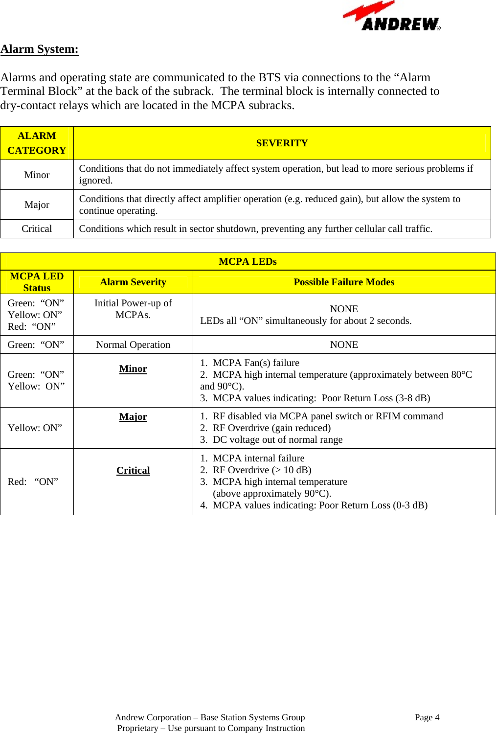
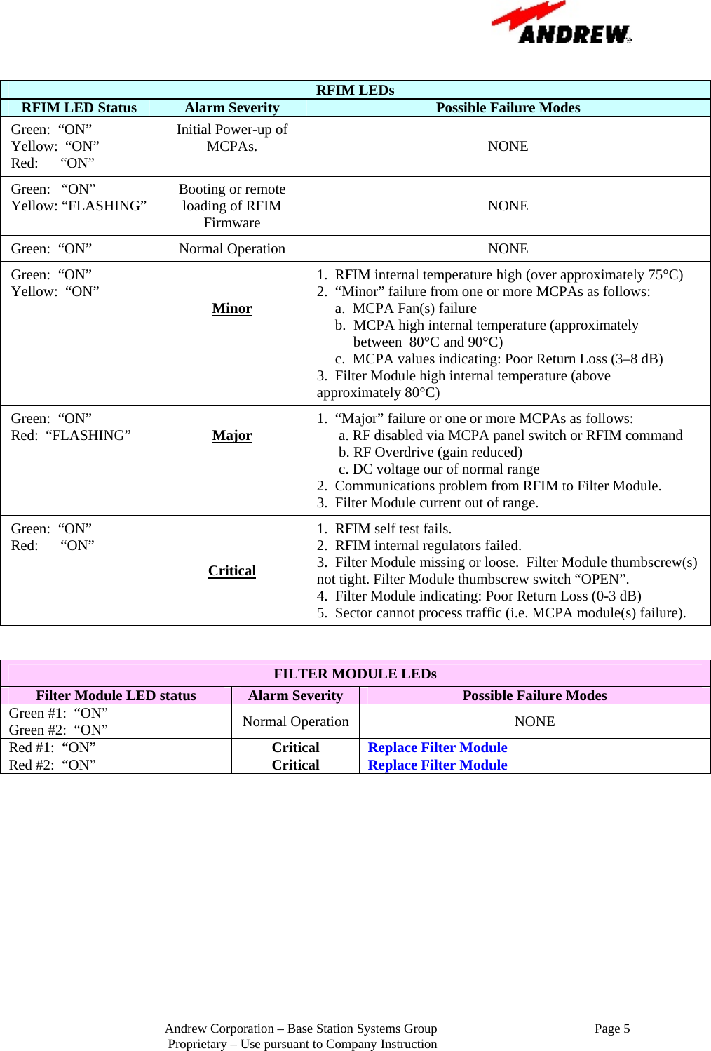
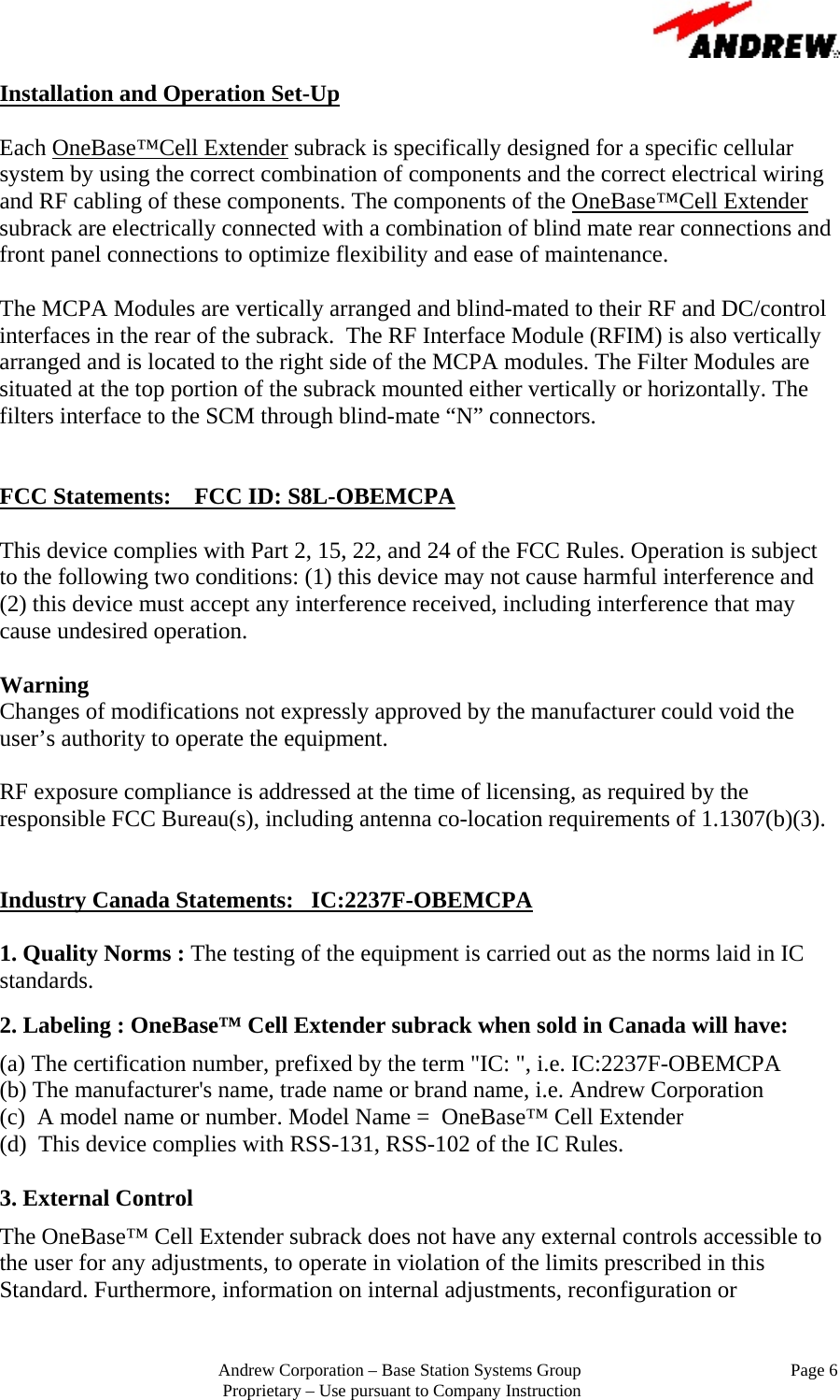
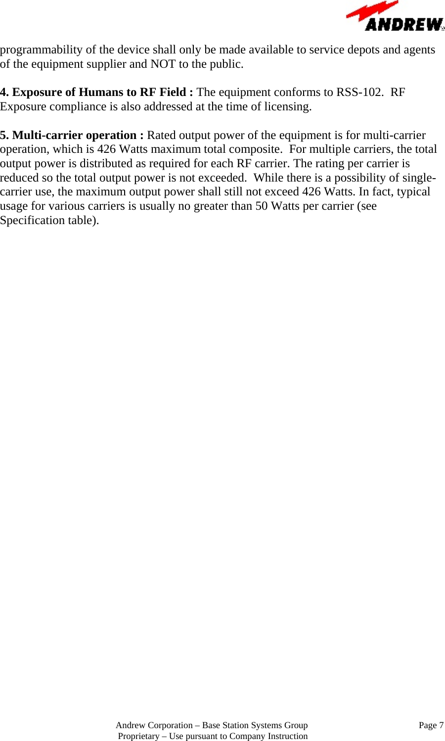
Andrew Base Station Subsystems Group OBEMCPA OneBase Cell Extender OBE-DB-X User Manual

Andrew Corporation, Base Station Subsystems Group OneBase Cell Extender OBE-DB-X

User Manual

      Andrew Corporation – Base Station Systems Group Proprietary – Use pursuant to Company Instruction             OneBase™ Cell Extender  Model: OBE-DB-X  Operation Instruction              December 20, 2006 Version. 1.0  Reference Numbers: FCC ID: S8L-OBEMCPA IC:2237F-OBEMCPA
                                                        Andrew Corporation – Base Station Systems Group                                                Page 1 Proprietary – Use pursuant to Company Instruction Introduction:  The  OneBase™ Cell Extender subrack is a high-power, mixed-mode RF front-end equipment solution which provides signal amplification and conditioning for both uplink and downlink cellular base station signals.  It is a highly modular design, consisting of a minimal set of unique field-replaceable units, capable of being configured and scaled for a variety of system level capacities and air interfaces including TDMA, GSM/EDGE, CDMA, WCDMA and analog air interfaces.   System Specifications:  System specifications for the OneBase™ Cell Extender Subrack are:  Parameter  Specification Frequency Bands    850 MHz Band Tx:   869-894 MHz 1900 MHz Band Tx: 1930-1990 MHz 25 MHz   (29 MHz for -20dB bandwidth, nominal) Operation Bandwidth 60 MHz   (70 MHz for -20dB bandwidth, nominal) Input / Output Impedances  50 Ohms Supply Voltage  +21 VDC to +30 VDC Nominal Passband Gain (dB)  55 dB     +/- 1 dB Power Amplifier Module Power Rating  135 Watts Subrack Capacity  4 MCPAs Total Rated Mean Output Power  426 Watts  (+56.3 dBm) Supported Output Power (Typical)  40 Watts/carrier  (WCDMA) 25 Watts/carrier  (TDMA) 25 Watts/carrier  (CDMA) 25 Watts/carrier   (GSM/EDGE) DC current draw  <140 Amps per Subrack In-Band emissions  -13 dBm/MHz Receive Path Noise Figure  3.5 dB
                                                        Andrew Corporation – Base Station Systems Group                                                Page 2 Proprietary – Use pursuant to Company Instruction Functional Blocks:  The OneBase™ Cell Extender subrack is comprised of the following functional blocks:  − RFIM (Radio Frequency Interface Module):  − MCPAs (Multi-carrier Power Amplifiers—850 MHz or 1900 MHz) − SCM (Switch Combiner Module) − Filter Module (850 MHz or 1900 MHz) − PDP (Power Distribution Panel) − Inputs and Outputs  Inputs and Outputs:  The amplifier is powered from a DC supply voltage which can range from 20VDC-to-30VDC (with a nominal voltage of 27 VDC).  The DC power is brought into the subrack at a terminal that is in the back of the subrack.    The RF signal is brought into the RFIM, passes into the amplifers, then through the SCM which is blind-mate connected to the amplifiers, and finally into the Filter Modules and subsequent antenna ports.
                                                        Andrew Corporation – Base Station Systems Group                                                Page 3 Proprietary – Use pursuant to Company Instruction System Pictures:                                             Front View                                                                      Rear View
                                                        Andrew Corporation – Base Station Systems Group                                                Page 4 Proprietary – Use pursuant to Company Instruction Alarm System:  Alarms and operating state are communicated to the BTS via connections to the “Alarm Terminal Block” at the back of the subrack.  The terminal block is internally connected to dry-contact relays which are located in the MCPA subracks.  ALARM CATEGORY  SEVERITY Minor  Conditions that do not immediately affect system operation, but lead to more serious problems if ignored.   Major  Conditions that directly affect amplifier operation (e.g. reduced gain), but allow the system to continue operating. Critical  Conditions which result in sector shutdown, preventing any further cellular call traffic.  MCPA LEDs MCPA LED Status  Alarm Severity  Possible Failure Modes Green:  “ON”    Yellow: ON” Red:  “ON” Initial Power-up of MCPAs.  NONE  LEDs all “ON” simultaneously for about 2 seconds. Green:  “ON”  Normal Operation  NONE Green:  “ON” Yellow:  ON” Minor   1.  MCPA Fan(s) failure 2.  MCPA high internal temperature (approximately between 80°C and 90°C). 3.  MCPA values indicating:  Poor Return Loss (3-8 dB) Yellow: ON”  Major   1.  RF disabled via MCPA panel switch or RFIM command 2.  RF Overdrive (gain reduced) 3.  DC voltage out of normal range Red:   “ON”  Critical   1.  MCPA internal failure 2.  RF Overdrive (> 10 dB) 3.  MCPA high internal temperature      (above approximately 90°C). 4.  MCPA values indicating: Poor Return Loss (0-3 dB)
                                                        Andrew Corporation – Base Station Systems Group                                                Page 5 Proprietary – Use pursuant to Company Instruction  RFIM LEDs RFIM LED Status  Alarm Severity  Possible Failure Modes Green:  “ON”              Yellow:  “ON” Red:      “ON”  Initial Power-up of MCPAs.   NONE Green:   “ON” Yellow: “FLASHING”  Booting or remote loading of RFIM Firmware  NONE Green:  “ON”  Normal Operation  NONE Green:  “ON” Yellow:  “ON”  Minor    1.  RFIM internal temperature high (over approximately 75°C) 2.  “Minor” failure from one or more MCPAs as follows:      a.  MCPA Fan(s) failure      b.  MCPA high internal temperature (approximately            between  80°C and 90°C)      c.  MCPA values indicating: Poor Return Loss (3–8 dB) 3.  Filter Module high internal temperature (above  approximately 80°C) Green:  “ON” Red:  “FLASHING”  Major    1.  “Major” failure or one or more MCPAs as follows:        a. RF disabled via MCPA panel switch or RFIM command       b. RF Overdrive (gain reduced)       c. DC voltage our of normal range 2.  Communications problem from RFIM to Filter Module. 3.  Filter Module current out of range. Green:  “ON” Red:      “ON” Critical 1.  RFIM self test fails. 2.  RFIM internal regulators failed. 3.  Filter Module missing or loose.  Filter Module thumbscrew(s) not tight. Filter Module thumbscrew switch “OPEN”. 4.  Filter Module indicating: Poor Return Loss (0-3 dB) 5.  Sector cannot process traffic (i.e. MCPA module(s) failure).   FILTER MODULE LEDs Filter Module LED status Alarm Severity  Possible Failure Modes Green #1:  “ON” Green #2:  “ON”  Normal Operation  NONE Red #1:  “ON”  Critical   Replace Filter Module   Red #2:  “ON”  Critical  Replace Filter Module
                                                        Andrew Corporation – Base Station Systems Group                                                Page 6 Proprietary – Use pursuant to Company Instruction Installation and Operation Set-Up  Each OneBase™Cell Extender subrack is specifically designed for a specific cellular system by using the correct combination of components and the correct electrical wiring and RF cabling of these components. The components of the OneBase™Cell Extender subrack are electrically connected with a combination of blind mate rear connections and front panel connections to optimize flexibility and ease of maintenance.  The MCPA Modules are vertically arranged and blind-mated to their RF and DC/control interfaces in the rear of the subrack.  The RF Interface Module (RFIM) is also vertically arranged and is located to the right side of the MCPA modules. The Filter Modules are situated at the top portion of the subrack mounted either vertically or horizontally. The filters interface to the SCM through blind-mate “N” connectors.     FCC Statements:    FCC ID: S8L-OBEMCPA  This device complies with Part 2, 15, 22, and 24 of the FCC Rules. Operation is subject to the following two conditions: (1) this device may not cause harmful interference and (2) this device must accept any interference received, including interference that may cause undesired operation.  Warning  Changes of modifications not expressly approved by the manufacturer could void the user’s authority to operate the equipment.  RF exposure compliance is addressed at the time of licensing, as required by the responsible FCC Bureau(s), including antenna co-location requirements of 1.1307(b)(3).   Industry Canada Statements:   IC:2237F-OBEMCPA  1. Quality Norms : The testing of the equipment is carried out as the norms laid in IC standards.   2. Labeling : OneBase™ Cell Extender subrack when sold in Canada will have:  (a) The certification number, prefixed by the term "IC: ", i.e. IC:2237F-OBEMCPA  (b) The manufacturer's name, trade name or brand name, i.e. Andrew Corporation (c)  A model name or number. Model Name =  OneBase™ Cell Extender (d)  This device complies with RSS-131, RSS-102 of the IC Rules.  3. External Control  The OneBase™ Cell Extender subrack does not have any external controls accessible to the user for any adjustments, to operate in violation of the limits prescribed in this Standard. Furthermore, information on internal adjustments, reconfiguration or
                                                        Andrew Corporation – Base Station Systems Group                                                Page 7 Proprietary – Use pursuant to Company Instruction programmability of the device shall only be made available to service depots and agents of the equipment supplier and NOT to the public.  4. Exposure of Humans to RF Field : The equipment conforms to RSS-102.  RF Exposure compliance is also addressed at the time of licensing.  5. Multi-carrier operation : Rated output power of the equipment is for multi-carrier operation, which is 426 Watts maximum total composite.  For multiple carriers, the total output power is distributed as required for each RF carrier. The rating per carrier is reduced so the total output power is not exceeded.  While there is a possibility of single-carrier use, the maximum output power shall still not exceed 426 Watts. In fact, typical usage for various carriers is usually no greater than 50 Watts per carrier (see Specification table).

Navigation menu