Apprion APP2X001 Wireless Access Point User Manual IONizer Reference Guide
Apprion, Inc. Wireless Access Point IONizer Reference Guide
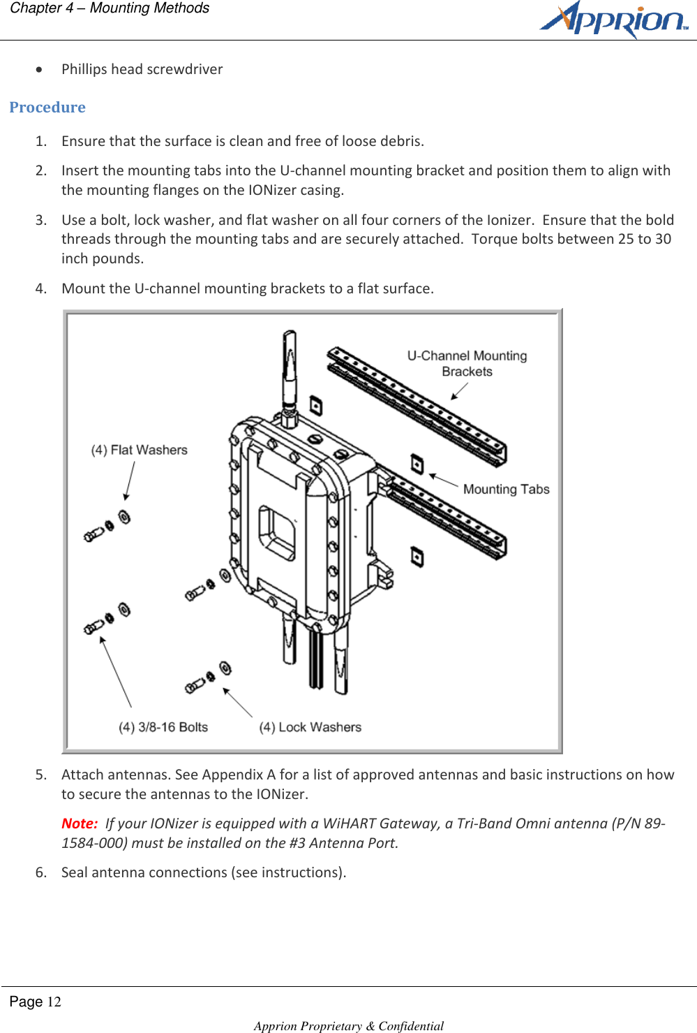
Apprion >
Contents
- 1. 4000 Series Manual
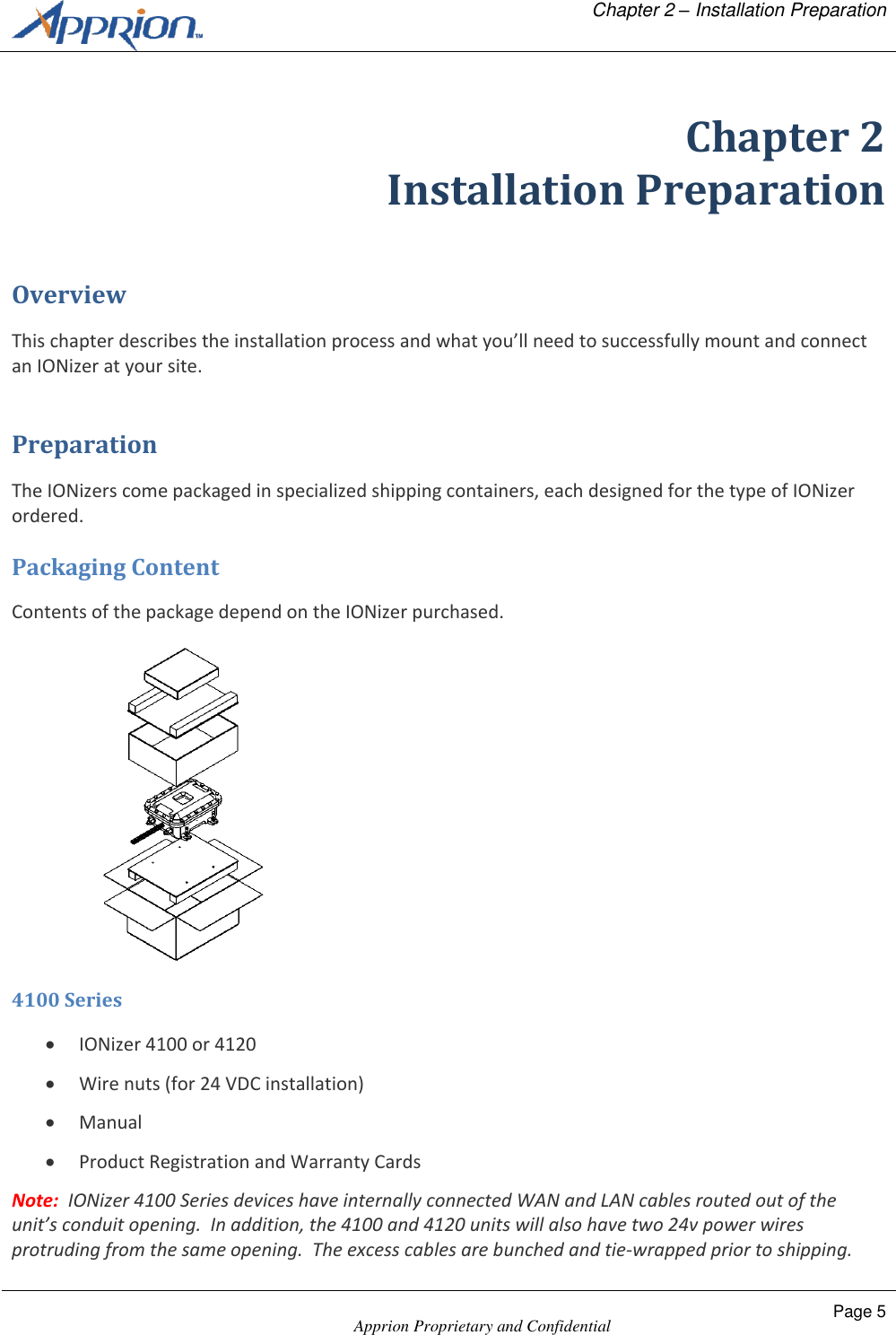
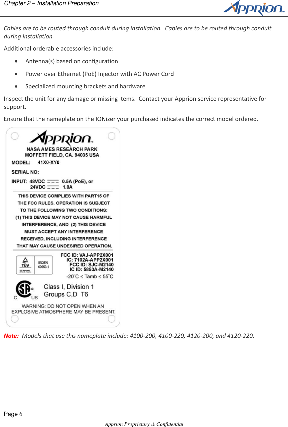
- 2. 4100 Series Manual
- 3. 4200 Series Manual
- 4. 4300 Series Manual
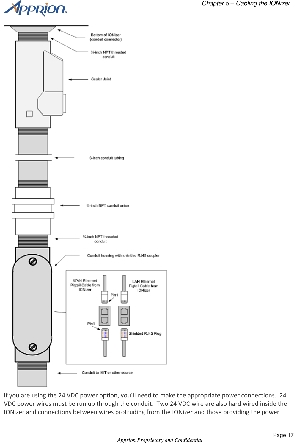
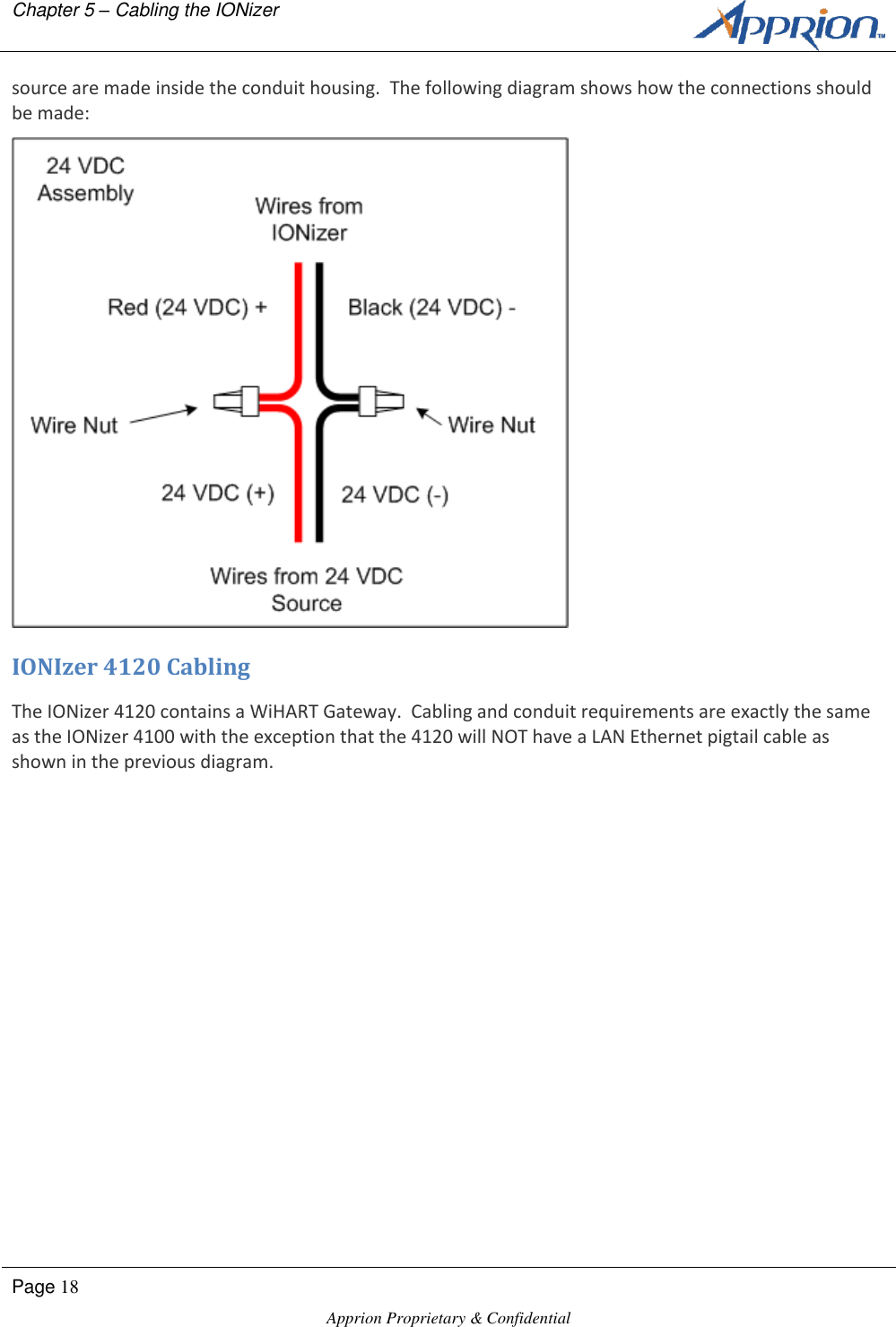
4100 Series Manual