Argus Technologies Co AGS-EW2104 Wireless Router User Manual WA601 WE2104
Argus Technologies Co Ltd Wireless Router WA601 WE2104
UserManual.wiki
>
Argus Technologies Co
>
AGS EW2104 User Manual
Manual
Navigation menu
Upload a User Manual
Namespaces
Wiki Guide
HTML
PDF
Info
Views
User Manual
Discussion / Help
Navigation

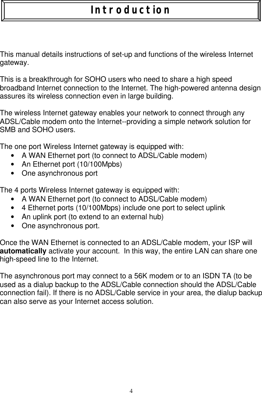
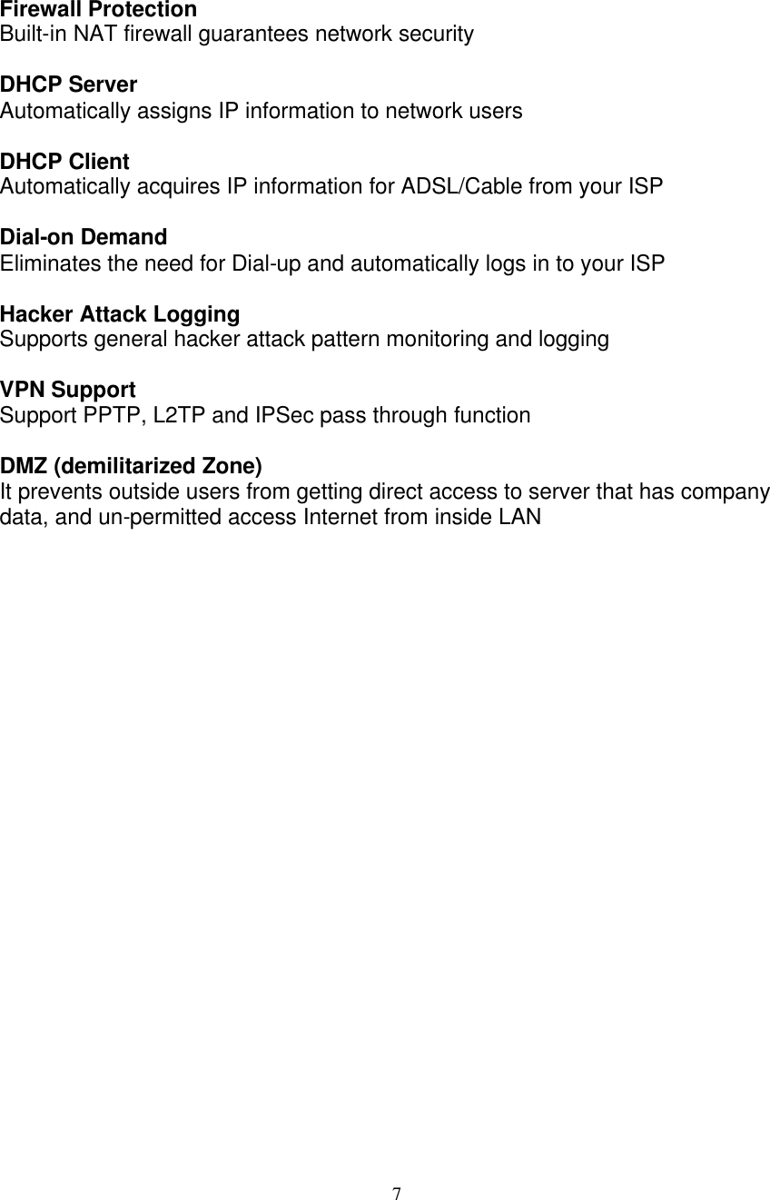
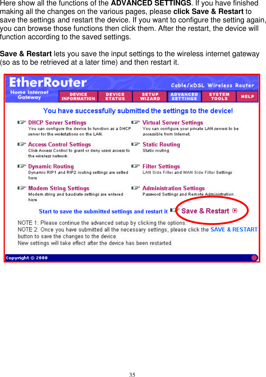
![10 4 - Ports Wireless Internet Gateway ADSL/Cable Router The Wireless Internet Gateway Front View LED indicators LINK (Green) LAN [1:4] Link/Act ACT (Green) Wireless (Green) Green LED will BLINK if packet is transmitting or receiving. Serial (Green) Green LED will LIGHT when a good link is established. WAN (Green) Green LED will LIGHT when a good link is established. STATUS (Yellow) Yellow LED will BLINK when device boot and upgrade firmware. POWER (Red) Red LED will LIGHT if the gateway is receiving power. Green LED will LIGHT when a good link is established. Green LED will BLINK if packet is transmitting or receiving.](https://usermanual.wiki/Argus-Technologies-Co/AGS-EW2104/User-Guide-179184-Page-10.png)
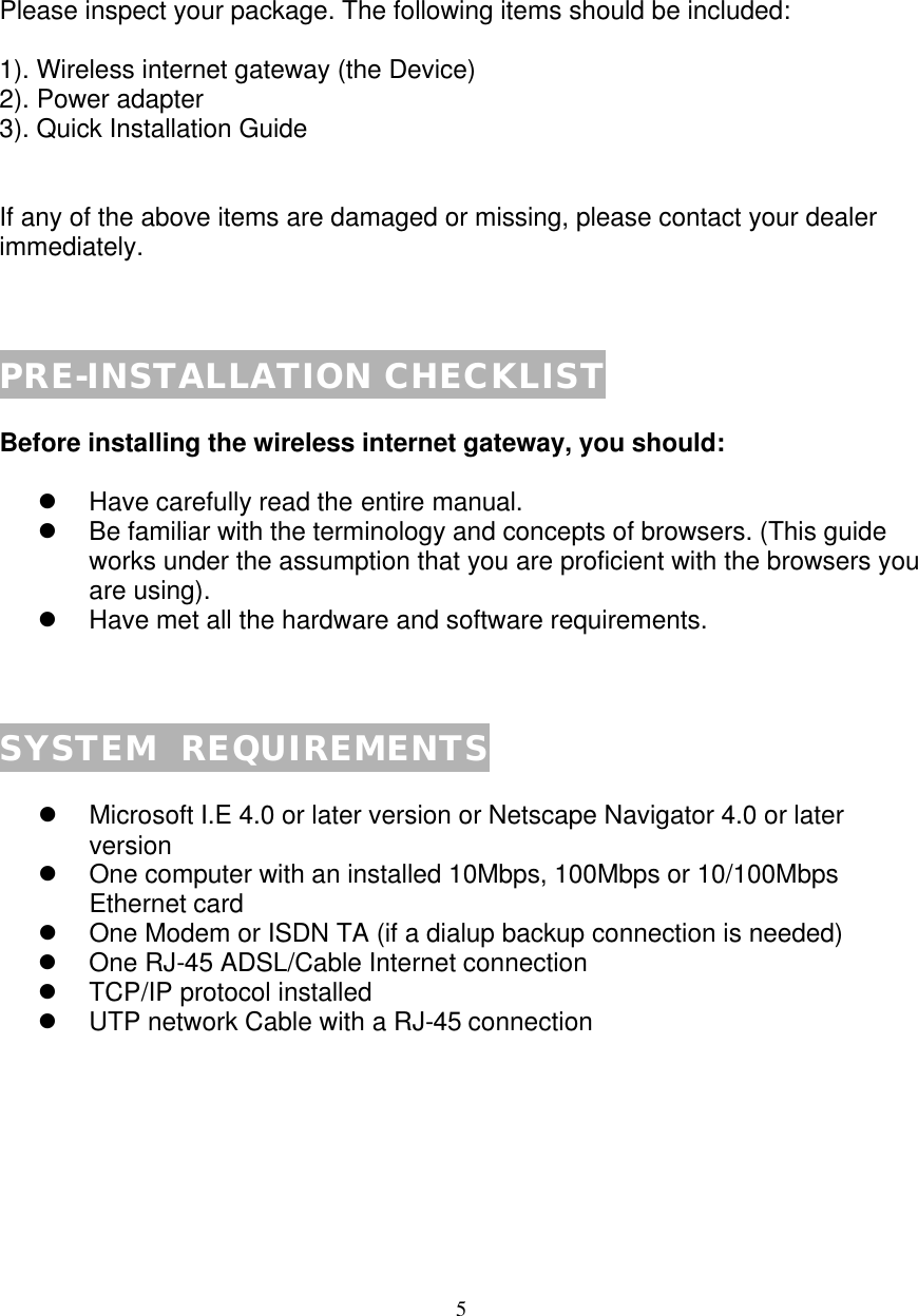
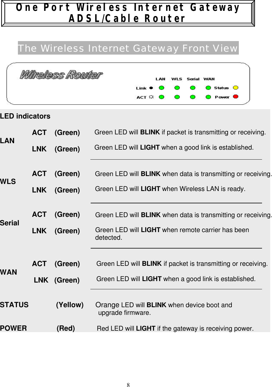
![11 The Wireless Internet Gateway Rear View The rear panel of the wireless Internet gateway is where all connections are made. POWER (5 VDC) The power port is where you will connect the AC to DC switching power adapter. WAN The WAN 10M Ethernet port is where you will connect your ASDL/Cable modem. Serial The Serial port is where you will connect the 56K modem or ISDN TA. LAN[1:4] The LAN port on the rear panel. This is where you will connect networked devices, such as PCs, ftp servers or anything else you want to put on your network. The Reset Button If you would like to load default settings, press the reset button and hold it for 5 ~ 6 seconds. It will load the factory default settings for the device. Please be careful. Do not press the reset button unless you want to clear the current data. NOTE¡I](https://usermanual.wiki/Argus-Technologies-Co/AGS-EW2104/User-Guide-179184-Page-11.png)

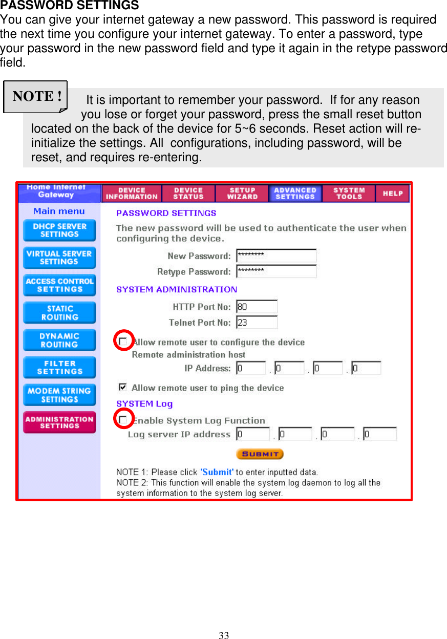
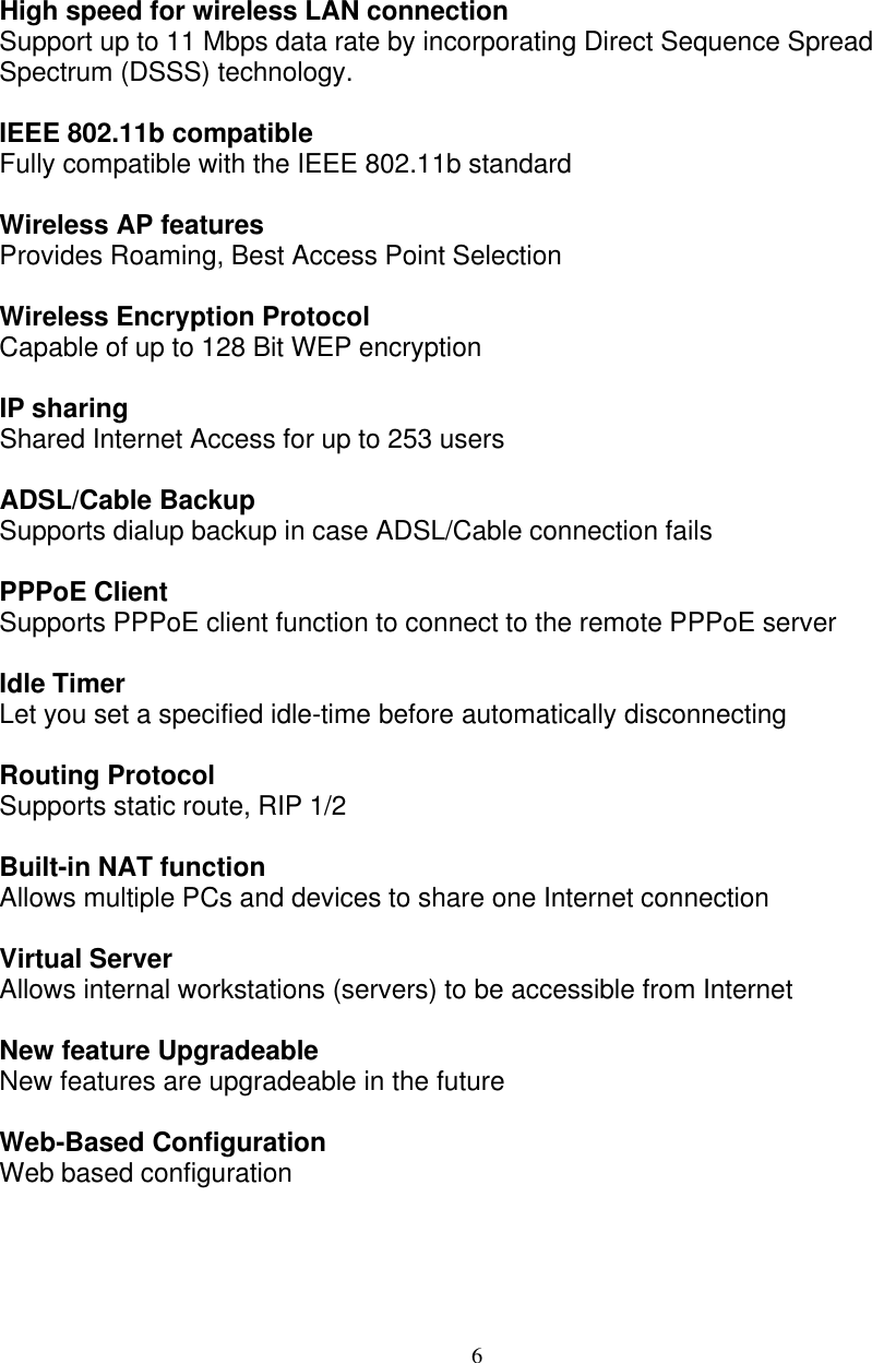
![34 http://<WAN IP Address>: <Port No> NOTE ! SYSTEM ADMINISTRATION Here allows remote user to configure and administrate the wireless internet gateway through Internet. The default port no for HTTP and TELNET are 80 and 23 respectively. The default IP address of remote administration host is: 0.0.0.0. (IP address 0.0.0.0 means that any PC on the network can remote access and manage the wireless internet gateway) If you use this function you have to enable the feature “Allow remote user to configure the device” first. Once you have enabled this function, type the wireless internet gateway WAN IP address (http://192.168.100.1:1023) into the browser of any or specific PC on the network. Once HTTP port no (NOT PORT 80) have be changed and the users of LAN terminal want to configure the wireless internet gateway, the users have to type the wireless internet gateway LAN IP address with port no (http://192.168.2.1:1023) SYSTEM LOG System Log function allows the administrator to assign the IP address of a server, on which, a log server is running. When a particular event happens, the router sends a notification to the log server. The log server can then present the log to the users. [Free log server can be download from internet, such as Kiwis SysLog Daemon] If you finished all the settings, please click Submit button to go to the next page…](https://usermanual.wiki/Argus-Technologies-Co/AGS-EW2104/User-Guide-179184-Page-34.png)