Arista Networks SS300AT60 SpectraGuard® Access Point User Manual
AirTight Networks, Inc. SpectraGuard® Access Point
user manual

Installation Guide
SS-300-AT-C-60
3x3 802.11abgn Access Point/Sensor
AirTight
®
Networks, Inc., 339 N. Bernardo Avenue, # 200, Mountain View, CA 94043
http://www.airtightnetworks.com
Product documentation is being enhanced continuously based on customer feedback. To obtain a latest copy of this document, visit
http://www.airtightnetworks.com/home/support.html
Thispagehasbeenintentionallyleftblank.

SS-300-AT-C-60 Access Point/Sensor
InstallationGuide

SS‐300‐AT‐C‐60InstallationGuide
ENDUSERLICENSEAGREEMENT
PleasereadtheEndUserLicenseAgreementbeforeinstallingtheSS‐300‐AT‐C‐60AccessPoint/Sensor.TheEndUserLicense
Agreementisavailableatthefollowinglocation‐.http://www.airtightnetworks.com/fileadmin/pdf/AirTight‐EULA.pdf.
InstallingtheSS‐300‐AT‐C‐60AccessPoint/SensorconstitutesyouracceptanceofthetermsandconditionsoftheEndUser
LicenseAgreement.
DISCLAIMER
THEINFORMATIONINTHISGUIDEISSUBJECTTOCHANGEWITHOUTANYPRIORNOTICE.
AIRTIGHT®NETWORKS,INC.ISNOTLIABLEFORANYSPECIAL,INCIDENTAL,INDIRECT,ORCONSEQUENTIAL
DAMAGESWHATSOEVER(INCLUDING,WITHOUTLIMITATION,DAMAGESFORLOSSOFBUSINESSPROFITS,
BUSINESSINTERRUPTION,LOSSOFBUSINESSINFORMATION,ORANYOTHERPECUNIARYLOSS)ARISINGOUTOF
THEUSEOFORINABILITYTOUSETHISPRODUCT.
THISPRODUCTHASTHECAPABILITYTOBLOCKWIRELESSTRANSMISSIONSFORTHEPURPOSEOFPROTECTING
YOURNETWORKFROMMALICIOUSWIRELESSACTIVITY.BASEDONTHEPOLICYSETTINGS,YOUHAVETHE
ABILITYTOSELECTWHICHWIRELESSTRANSMISSIONSAREBLOCKEDAND,THEREFORE,THECAPABILITYTO
BLOCKANEXTERNALWIRELESSTRANSMISSION.IFIMPROPERLYUSED,YOURUSAGEOFTHISPRODUCTMAY
VIOLATEUSFCCPART15ANDOTHERLAWS.BUYERACKNOWLEDGESTHELEGALRESTRICTIONSONUSAGEAND
UNDERSTANDSANDWILLCOMPLYWITHUSFCCRESTRICTIONSASWELLASOTHERGOVERNMENT
REGULATIONS.AIRTIGHTISNOTRESPONSIBLEFORANYWIRELESSINTERFERENCECAUSEDBYYOURUSEOF
THEPRODUCT.AIRTIGHTANDITSAUTHORIZEDRESELLERSORDISTRIBUTORSWILLASSUMENOLIABILITYFOR
ANYDAMAGEORVIOLATIONOFGOVERNMENTREGULATIONSARISINGFROMYOURUSAGEOFTHEPRODUCT,
EXPECTASEXPRESSLYDEFINEDINTHEINDEMNITYSECTIONOFTHISDOCUMENT.
LIMITATIONOFLIABILITY
AirTightwillnotbeliabletocustomeroranyotherpartyforanyindirect,incidental,special,consequential,exemplary,or
reliancedamagesarisingoutoforrelatedtotheuseofSpectraGuard®Enterpriseunderanylegaltheory,includingbutnot
limitedtolostprofits,lostdata,orbusinessinterruption,evenifAirTightknowsoforshouldhaveknownofthepossibilityof
suchdamages.Regardlessofthecauseofactionortheformofaction,AirTight’stotalcumulativeliabilityforactualdamages
arisingoutoforrelatedtotheuseofSpectraGuard®EnterprisewillnotexceedthepricepaidforSpectraGuard®Enterprise.
Copyright©2012AirTight®Networks,Inc.AllRightsReserved.
AirTight®Networks,TheAirTightlogo,andSpectraGuard®areregisteredtrademarksofAirTight®Networks.Allother
productsandservicesaretrademarks,registeredtrademarks,andservicemarksorregisteredservicemarksoftheirrespective
owners.
ThisproductcontainscomponentsfromOpenSourcesoftware.Thesecomponentsaregovernedbythetermsandconditions
oftheGNUPublicLicense.Toreadthesetermsandconditionsvisithttp://www.gnu.org/copyleft/gpl.html.
ThisproductisprotectedbyoneormoreofU.S.patentNos.7,002,943,7,154,874,7,216,365,7,333,800,7,333,481,7,339,914,
7,406,320,7,440,434,7,447,184,7,496,094,7,536,723,7,558,253,7,710,933,7,751,393,7,764,648,7,804,808,7,856,209,7,856,656,
7,970,894,7,971,253,8,032,939;AustralianpatentNo.200429804;U.K.patentNo.2410154;JapanpatentNo.4639195,andany
otherslistedatwww.airtightnetworks.com/patents.Morepatentspending.

SS‐300‐AT‐C‐60InstallationGuide
FEDERALCOMMUNICATIONSCOMMISSIONINTERFERENCESTATEMENT
ThisequipmenthasbeentestedandfoundtocomplywiththelimitsforaClassBdigitaldevice,pursuanttopart15ofthe
FCCRules.Theselimitsaredesignedtoprovidereasonableprotectionagainstharmfulinterferenceinaresidentialinstallation.
Thisequipmentgenerates,usesandcanradiateradiofrequencyenergyand,ifnotinstalledandusedinaccordancewiththe
instructions,maycauseharmfulinterferencetoradiocommunications.However,thereisnoguaranteethatinterferencewill
notoccurinaparticularinstallation.Ifthisequipmentdoescauseharmfulinterferencetoradioortelevisionreception,which
canbedeterminedbyturningtheequipmentoffandon,theuserisencouragedtotrytocorrecttheinterferencebyoneor
moreofthefollowingmeasures:
‐Reorientorrelocatethereceivingantenna.
‐Increasetheseparationbetweentheequipmentandreceiver.
‐Connecttheequipmentintoanoutletonacircuitdifferentfromthattowhichthereceiverisconnected.
‐Consultthedealeroranexperiencedradio/TVtechnicianforhelp.
CAUTION
Anychangesormodificationsnotexpresslyapprovedbytheguaranteeofthisdevicecouldvoidtheuserʹsauthorityto
operatetheequipment.
Labelingrequirements
ThisdevicecomplieswithPart15oftheFCCRules.Operationissubjecttothefollowingtwoconditions:(1)thisdevicemay
notcauseharmfulinterference,and(2)thisdevicemustacceptanyinterferencereceived,includinginterferencethatmay
causeundesiredoperation.
RFexposurewarning
This equipment must be installed and operated in accordance with provided instructions and the antenna(s) used for this
transmitter must be installed to provide a separation distance of at least 20 cm from all persons and must not be co-located or
operating in conjunction with any other antenna or transmitter. End-users and installers must be provide with antenna
installation instructions and transmitter operating conditions for satisfying RF exposure compliance.
Thisdeviceisoperationin5.15–5.25GHzfrequencyrange,thenrestrictedinindooruseonly,Outdooroperationsinthe
5150~5250MHzisprohibit.
Canada,IndustryCanada(IC)Notices
ThisClassBdigitalapparatuscomplieswithCanadianICES‐003andRSS‐210.
Operationissubjecttothefollowingtwoconditions:(1)thisdevicemaynotcauseinterference,and(2)thisdevicemustaccept
anyinterference,includinginterferencethatmaycauseundesiredoperationofthedevice.
RadioFrequency(RF)ExposureInformation
TheradiatedoutputpoweroftheWirelessDeviceisbelowtheIndustryCanada(IC)radiofrequencyexposurelimits.The
WirelessDeviceshouldbeusedinsuchamannersuchthatthepotentialforhumancontactduringnormaloperationis
minimized.
ThisdevicehasalsobeenevaluatedandshowncompliantwiththeICRFExposurelimitsundermobileexposureconditions.
(antennasaregreaterthan20cmfromapersonʹsbody).

SS‐300‐AT‐C‐60InstallationGuide
Canada,avisdʹIndustryCanada(IC)
CetappareilnumériquedeclasseBestconformeauxnormescanadiennesICES‐003etRSS‐210.
Sonfonctionnementestsoumisauxdeuxconditionssuivantes:(1)cetappareilnedoitpascauserdʹinterférenceet(2)cet
appareildoitacceptertouteinterférence,notammentlesinterférencesquipeuventaffectersonfonctionnement.
Informationsconcernantlʹexpositionauxfréquencesradio(RF)
Lapuissancedesortieémiseparl’appareildesansfilestinférieureàlalimitedʹexpositionauxfréquencesradiodʹIndustry
Canada(IC).Utilisezl’appareildesansfildefaçonàminimiserlescontactshumainslorsdufonctionnementnormal.
CepériphériqueaégalementétéévaluéetdémontréconformeauxlimitesdʹexpositionauxRFdʹICdansdesconditions
dʹexpositionàdesappareilsmobiles(lesantennessesituentàmoinsde20cmducorpsdʹunepersonne).
FCCNOTICE:
TocomplywithFCCpart15rulesintheUnitedStates,thesystemmustbeprofessionallyinstalledtoensurecompliancewith
thePart15certification.Itistheresponsibilityoftheoperatorandprofessionalinstallertoensurethatonlycertifiedsystems
aredeployedintheUnitedStates.Theuseofthesysteminanyothercombination(suchasco‐locatedantennastransmitting
thesameinformation)isexpresslyforbidden.
OnlytheantennaslistedbelowareallowedtobeusedwiththeEUToutputpower.
AntennaList
No.ManufacturerPartNo.PeakGainNOTE
1.JOYMAX
JWX‐614XRSXX‐3613dBifor2.4GHz
5dBifor5.15~5.25GHz
5dBifor5.725~5.850GHz
ExternalAntenna
(Dipole)
2.MAG.LAYERSMSA‐3810‐2G4C1‐A36
MSA‐3810‐2G4C1‐A37
MSA‐3810‐2G4C1‐A38
MSA‐3810‐2G4C1‐B3
MSA‐3810‐2G4C1‐B4
4.14dBifor2.4GHz
2.64dBifor5.15~5.25GHz
5.72dBifor5.725~5.850GHz
InternalAntenna
(PIFA)

TableofContents
SS‐300‐AT‐C‐60InstallationGuide
TableofContents
CHAPTER 1GETTING STARTED...................................................................................................................................1
1.1BEFORE YOU BEGIN.......................................................................................................................................................1
1.2HOW TO GET MORE INFORMATION ..................................................................................................................................1
1.3CONTACT INFORMATION.................................................................................................................................................1
CHAPTER 2PACKAGE CONTENTS..............................................................................................................................2
CHAPTER 3SS-300-AT-C-60 OVERVIEW......................................................................................................................3
CHAPTER 4INSTALLING SS-300-AT-C60.....................................................................................................................7
4.1ZERO CONFIGURATION OF SS-300-AT-C-60 AS SENSOR ................................................................................................7
4.2CONNECTING SS-300-AT-C-60......................................................................................................................................7
4.2.1Mount SS-300-AT-C-60 ..........................................................................................................................................7
4.2.1.1Ceiling Mounting..................................................................................................................................................................7
4.2.1.2Wall or Electrical Box Mounting ..........................................................................................................................................9
4.2.2Prerequisites to connect the device to the network.................................................................................................9
4.2.3Using SS-300-AT-C-60 with PoE..........................................................................................................................10
4.2.4Using SS-300-AT-C-60 with power adapter.........................................................................................................10
CHAPTER 5MANUALLY CONFIGURING THE SS-300-AT-C-60 AS SENSOR .....................................................12
5.1INTRODUCTION.............................................................................................................................................................12
5.2CONFIGURING SENSOR THROUGH CONFIG SHELL ........................................................................................................12
5.2.1Invoke HyperTerminal (or minicom)....................................................................................................................12
5.2.1.1Launching HyperTerminal ..................................................................................................................................................12
5.2.1.2Defining a New HyperTerminal Connection.......................................................................................................................13
5.2.1.3Specifying HyperTerminal Connection Details...................................................................................................................14
5.2.1.4Editing Serial Port Settings.................................................................................................................................................14
5.2.2Log in and Change the Default Password............................................................................................................15
5.2.3Set Server Discovery ............................................................................................................................................15
5.2.4Set Sensor Mode...................................................................................................................................................15
5.2.5Configure Network Settings..................................................................................................................................16
5.2.5.1Configure IPv6 settings.......................................................................................................................................................16
5.2.5.2How to configure Communication Key or Passphrase........................................................................................................16
CHAPTER 6SS-300-AT-C-60 CONFIG SHELL COMMANDS ..................................................................................17
CHAPTER 7SS-300-AT-C-60 TROUBLESHOOTING.................................................................................................19
CHAPTER 8APPENDIX A: SERVER SENSOR MUTUAL AUTHENTICATION ...................................................21

TableofFigures
SS‐300‐AT‐C‐60InstallationGuide
TableofFigures
FIGURE 1.SS-300-AT-C-60 PACKAGE CONTENTS.......................................................................................................................................2
FIGURE 2.FRONT PANEL OF SS-300-AT-C-60.............................................................................................................................................3
FIGURE 3.REAR PANEL OF SS-300-AT-C-60...............................................................................................................................................5
FIGURE 4.SIDE PANEL OF SS-300-AT-C-60................................................................................................................................................6
FIGURE 5.ATTACHING THE METAL SLIDER..................................................................................................................................................8
FIGURE 6.CLIPPING THE METAL CEILING-BRACKET ....................................................................................................................................8
FIGURE 7.SLIDING THE MOVABLE SECTION .................................................................................................................................................8
FIGURE 8.FINAL POSITIONING OF THE SENSOR ............................................................................................................................................9
FIGURE 9.HOLES FOR INSERTING SCREWS ...................................................................................................................................................9
FIGURE 10.POWER UP AND CONNECT SS-300-AT-C-60 USING POE.............................................................................................................10
FIGURE 11.POWER UP SS-300-AT-C-60.....................................................................................................................................................10
FIGURE 12.CONNECT SS-300-AT-C-60 TO THE NETWORK.......................................................................................................................... 11
FIGURE 13.CONNECTING SS-300-AT-C-60 TO YOUR COMPUTER USING A SERIAL CABLE ............................................................................12
FIGURE 14.OPENING HYPERTERMINAL ......................................................................................................................................................13
FIGURE 15.DEFINE A NEW HYPERTERMINAL CONNECTION FOR SENSOR.....................................................................................................13
FIGURE 16.SPECIFY HYPERTERMINAL CONNECTION DETAILS.....................................................................................................................14
FIGURE 17.EDIT SERIAL PORT SETTINGS FOR SENSOR SS-300-AT-C-60.....................................................................................................15
FIGURE 18.SET SERVER DISCOVERY COMMAND ...........................................................................................................................................15
FIGURE 19.SET SENSOR MODE COMMAND FOR SS-300-AT-C-60 ................................................................................................................. 16

SS‐300‐AT‐C‐60InstallationGuide
1
Chapter1GettingStarted
1.1BeforeYouBegin
ThankyouforpurchasingSS‐300‐AT‐C‐60fromAirTight®Networks,Inc.TheSS‐300‐AT‐C‐60isa3x3802.11abgnAccess
Point/Sensor.
PleasereadtheEULAbeforeinstallingtheSS‐300‐AT‐C‐60.Installingthesensorconstitutesyouracceptanceofthetermsand
conditionsoftheEULAmentionedaboveinthisdocument.Thisproductcannotberentedorleased–youarethesoleownerof
theproduct.
ThisinstallationguidegivesanoverviewofthepackagecontentsandexplainshowtomountandconfiguretheSS‐300‐AT‐
C60.Thisguidecontainsthefollowingchapters:
• PackageContents:Liststhecomponentsincludedinthesystempackage.
• SS‐300‐AT‐C‐60Overview:Providesanoverviewofsensor.
• Installingthedevice:DescribeshowtoconnectandinstallSS‐300‐AT‐C‐60.
• ManuallyConfiguringthedevice:DescribeshowtoconfigureSS‐300‐AT‐C‐60throughtheconfigshell.
• ConfigShellCommands:Listsapre‐definedsetofcommandsthatallowyoutoconfigureandviewthestatusofthe
sensors.
• Troubleshooting:Providestroubleshootingtipswhileinstallingthesensor.
1.2Howtogetmoreinformation
Toreceiveimportantnewsonproductupdates,pleasevisitourwebsiteatsupport@airtightnetworks.com.
1.3ContactInformation
AirTight®Networks,Inc.
339N,BernardoAvenue,Suite#200,
MountainView,CA94043
Tel:(650)961‐1111
Fax:(650)963‐3388
Fortechnicalsupportsendanemailtosupport@airtightnetworks.com.
SS‐300‐AT‐C‐60InstallationGuide
2
Chapter2PackageContents
ThischapterliststhecomponentsincludedintheSS‐300‐AT‐C‐60devicepackage.SS‐300‐AT‐C‐60isa3x3802.11abgnAccess
Point/Sensor.ItcanfunctioneitherasanAPorasasensordependingonhowitisconfigured.
PleaseensurethatthefollowingitemsareincludedintheSS‐300‐AT‐C‐60devicepackage.Ifthepackageisnotcomplete,
pleasecontactAirTight®Networks,Inc.TechnicalSupportatsupport@airtightnetworks.com,orreturnthepackagetothe
vendorordealerwhereyoupurchasedtheproduct.
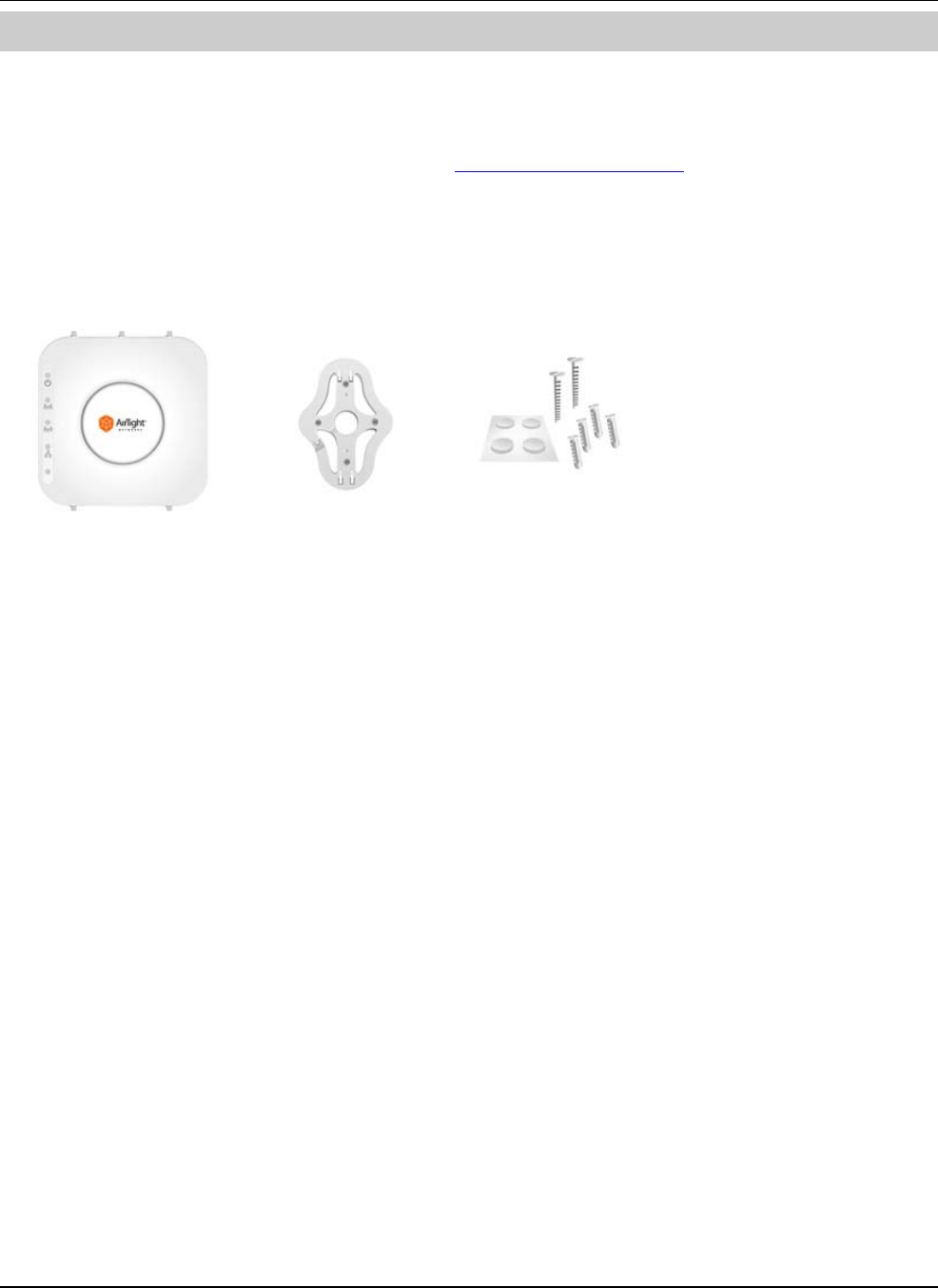
ThecontentsoftheSS‐300‐AT‐C‐60packageareasfollows:
• SS‐300‐AT‐C‐60
• MountingBracketandAccessories
Figure 1. SS-300-AT-C-60 Package Contents
SS‐300‐AT‐C‐60InstallationGuide
Chapter3SS‐300‐AT‐C‐60Overview
ThischapterprovidesanoverviewoftheSS‐300‐AT‐C‐60anddescribesindetailaboutthefollowing.
• FrontpanelofSS‐300‐AT‐C‐60
• RearpanelofSS‐300‐AT‐C‐60
SS‐300‐AT‐C‐60isa802.11naccesspoint/sensordevicewithaCiscocompatibleconsoleport.Ithasfiveexternalantennaports‐
threeatthetopandtwoatthebottom.Itisadualradiodevicecapableofactingasanaccesspointorasensor.Thetopthree
antennasareforradio1andthebottomtwoantennasareforradio2.
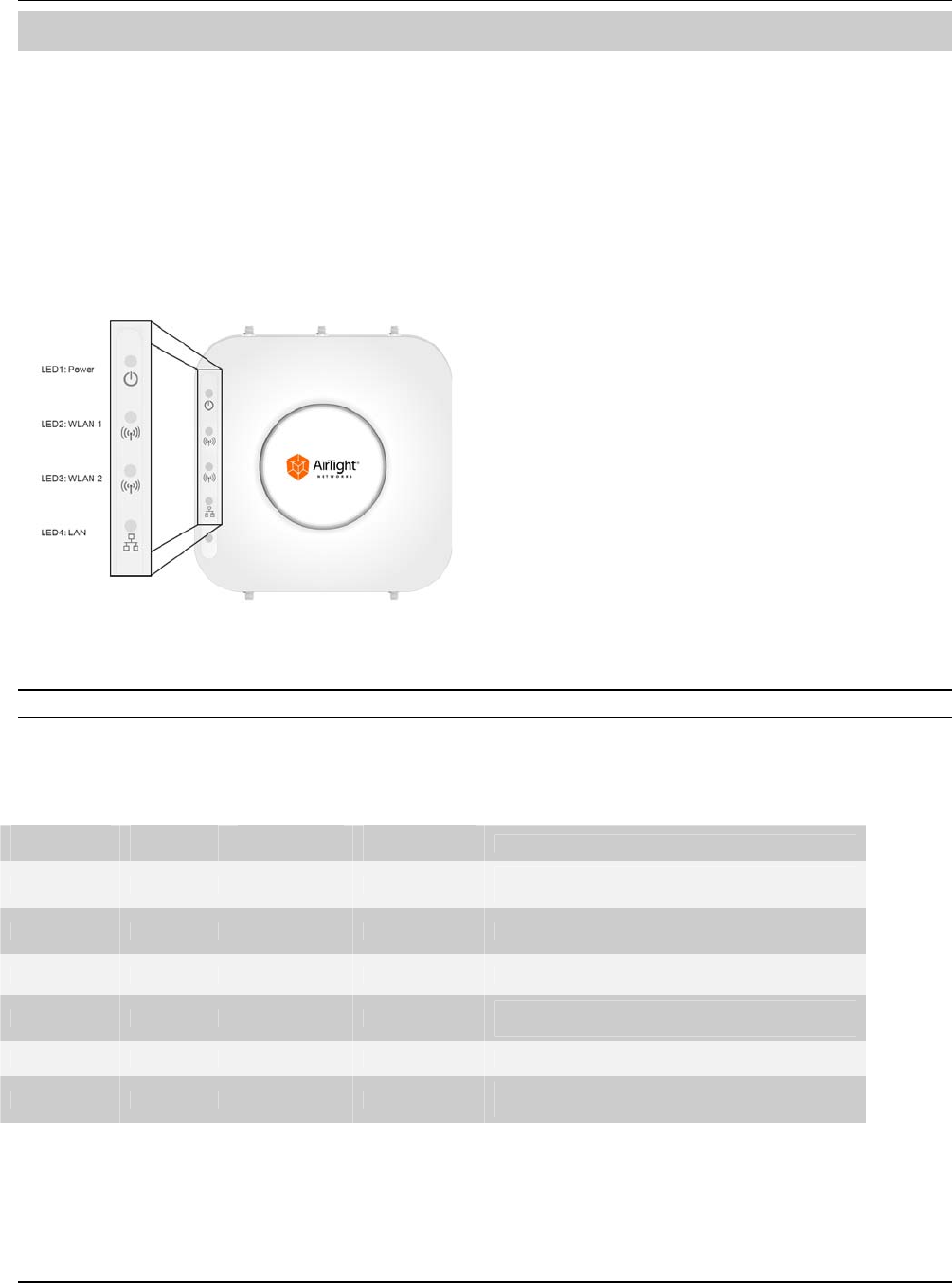
ThefrontpaneloftheSS‐300‐AT‐C‐60hasLEDsthatindicatetheworkingofthedevice.
Figure 2. Front Panel of SS-300-AT-C-60
Note:LED5,thatisnotvisibleinthezoomed‐inviewintheabovefigure,isnotinuse.OnlyLED1,LED2,LED3andLED4areinuse.
ThefollowingtableindicatesvariousdevicestatesusingtheLEDsonthedevice,whenthedeviceisinAPmode.
Table 1. LED details for SS-300-AT-C-60 in AP mode
LED1 or
Power
LED2 or
WLAN1
LED3 or
WLAN2
LED4 or
LANDescription
Solid Green Any Any Solid Green The AP is receiving power and is working
normally. The AP is connected to the Server.
Solid Green Off Slow Blink Slow Blink The AP upgrade is in progress.
Solid Orange Any Any Solid Green The AP is unable to get Ethernet link.
Solid Orange Any Any Fast Blink The AP did not receive a valid IP address via the
DHCP.
Solid Orange Any Any Slow Blink The AP is unable to connect to the Server.
Off Off Off Off The AP is not powered on or it is in the process
of starting up.
WLAN1andWLAN2LEDswillblinkwhenthereisactivityontherespectiveradios.
ThefollowingtableindicatesvariousdevicestatesusingtheLEDsonthedevice,whenthedeviceisinsensormode.

SS‐300‐AT‐C‐60InstallationGuide
Table 2. LED details for SS-300-AT-C-60 in sensor mode
LED1 or
Power
LED2 or
WLAN1
LED3 or
WLAN2
LED4 or
LANDescription
Solid Green Solid Green Solid Green Solid Green The Sensor is receiving power and is working
normally. The Sensor is connected to the
Server.
Solid Green Solid Green Fast Blink Solid Green The Sensor is performing troubleshooting on
802.11a/n.
Solid GreenSolid GreenSlow BlinkSolid GreenThe Sensor is performing intrusion prevention
on 802.11a/n.
Solid GreenFast BlinkSolid GreenSolid GreenThe Sensor is performing troubleshooting on
802.11b/g/n.
Solid GreenFast BlinkFast BlinkSolid GreenThe Sensor is performing troubleshooting on
802.11b/g/n and 802.11a/n.
Solid GreenFast BlinkSlow BlinkSolid GreenThe Sensor is performing troubleshooting on
802.11b/g/n and intrusion prevention on
802.11a/n.
Solid GreenSlow BlinkSolid GreenSolid GreenThe Sensor is performing intrusion prevention
on 802.11b/g/n.
Solid GreenSlow BlinkFast BlinkSolid GreenThe Sensor is performing intrusion prevention
on 802.11b/g/n and troubleshooting on
802.11a/n.
Solid GreenSlow BlinkSlow BlinkSolid GreenThe Sensor is performing intrusion prevention
on 802.11b/g/n and 802.11a/n.
Solid Green Off Slow Blink Slow Blink The Sensor upgrade is in progress.
Solid Orange Any Any Solid Green The Sensor is unable to get Ethernet link.
Solid Orange Any Any Fast Blink The Sensor did not receive a valid IP address
via the DHCP.
Solid Orange Any Any Slow Blink The Sensor is unable to connect to the Server.
Solid OrangeSolid GreenAnyAnyThere is an error on 802.11a/b/g/n interfaces.
Solid OrangeAnySolid GreenAnyThe Sensor is experiencing a software error.
OffOffOffOffThe Sensor is not powered on or it is in the
process of starting up.
ThefollowingtableindicatesvariousdevicestatesusingtheLEDsonthedevice,whenthedeviceisinAP/sensorcombomode,
thatisoneradioisconfiguredtofunctionasanAPandtheotherradioisconfiguredtofunctionasasensor.
Table 3. LED details for SS-300-AT-C-60 in AP/sensor combo mode
LED1 or
Power LED2 or
WLAN1 LED3 or
WLAN2 LED4 or
LAN Description
Solid Green Solid Green Any Solid Green The AP-Sensor is receiving power and is working
normally. The AP-Sensor is connected to the
Server.
Solid Green Fast Blink Any Solid Green The Sensor is performing Troubleshooting on
802.11a/b/g/n
Solid Green Slow Blink Any Solid Green The Sensor is performing Prevention on
802.11a/b/g/n
Solid Green Off Slow Blink Slow Blink The AP upgrade is in progress.
Solid Orange Any Any Solid Green The AP is unable to get Ethernet link.
Solid Orange Any Any Fast Blink The AP did not receive a valid IP address via the
DHCP.
SS‐300‐AT‐C‐60InstallationGuide
Solid Orange Any Any Slow Blink The AP is unable to connect to the Server.
Off Off Off Off The AP is not powered on or it is in the process of
starting up.
WLAN2LEDwillblinkwhenthereisactivityontheAPradio.
Note:Ifnochannelsarespecifiedformonitoringandpreventiononthesensorradio,therespectiveLEDwillhavenoactivityanditwill
notglow.
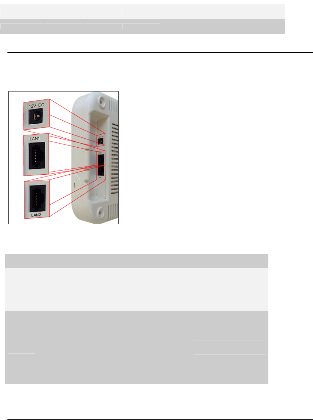
TherearpaneloftheSS‐300‐AT‐C‐60hastwoEthernetports‐LAN1andLAN2,thatenablesthedevicetobeconnectedtothe
wiredLANthroughaswitchorahubandprovidesthepowerforthedeviceusing802.3afstandard.
Figure 3. Rear Panel of SS-300-AT-C-60
Table 4. Rear Panel Port Settings for SS-300-AT-C-60
Port Description Connector
Type Speed/Protocol
Ethernet
(LAN1)
This enables the device to be connected to
the wired LAN through a switch or a hub.
This connection allows the SpectraGuard
Sensor to communicate with the
SpectraGuard Enterprise® Server.
This port also provides the power for the
device using 802.3af standard
RJ-45 10/100/1000 Mbps Ethernet
Power over Ethernet
Ethernet
(LAN2)
This enables the device to be connected to
the wired LAN through a switch or a hub.
This connection allows the SpectraGuard
Sensor to communicate with the
SpectraGuard Enterprise® Server.
This port also provides the power for the
device using 802.3af standard
RJ-45 10/100/1000 Mbps Ethernet
Power over Ethernet
SS‐300‐AT‐C‐60InstallationGuide
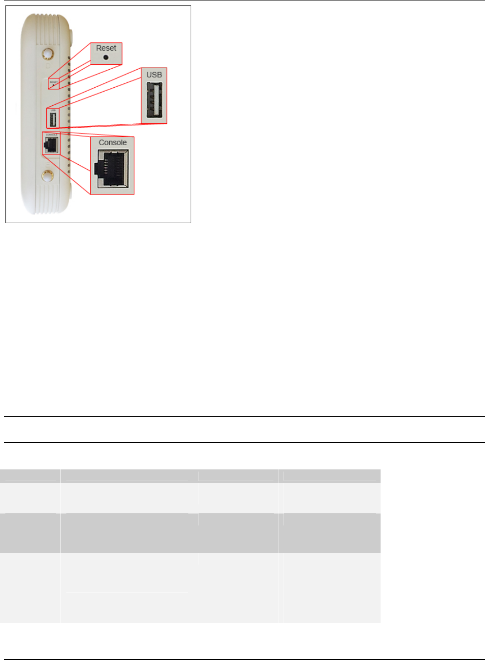
Figure 4. Side Panel of SS-300-AT-C-60
Thesidepanelhasthefollowingports:
• Serialport:ConnectstheSS‐300‐AT‐C‐60devicetoserialterminalemulationprogramssuchasHyperTerminalfor
WindowsorminicomforLinux.
• USBport:ConnectstheSS‐300‐AT‐C‐60devicetoaUSBdevice.
• Resetswitch:ResetstheSS‐300‐AT‐C‐60devicetofactorydefaults.ToresettheSS‐300‐AT‐C‐60device,pressthe
Resetswitchandpowercycle(removethepowercableonceandconnectitbackagain)thedevice,untilallLEDs
blinkgreen.Pressing<Reset>whilethedeviceisrunningwillnothaveanyeffect.Thefollowingsettingsarereset:
ConfigShellPasswordisresettoconfig.
ServerDiscoveryvalueiserasedandchangedtothedefault,wifi‐security‐server.
AlltheVLANconfigurationsarelost.
DevicemodeischangedtoSensorOnly.
IfstaticIPwasconfiguredonthedevice,theIPiserasedandDHCPmodeisset.
Afterreset,alltheLEDswillblinkonce,implyingthattheresetissuccessful.
Note:ForSS‐300‐AT‐C‐60,theuserisexpectedtopressandholdtheresetswitchwhileapower‐cyclefor30seconds(actuallytakes26
secondsfortheresettocomplete).
Table 5. Side Panel Port Settings for SS-300-AT-C-60
Port Description Connector Type Speed/Protocol
Reset Allows resetting of
SpectraGuard Sensor™ to
factory settings.
Pin-hole
push-button Hold down and power
cycle the Sensor to
reset
USB Connects the SS-300-AT-C-60
device to a USB device
Console Enables a serial connection to
establish terminal sessions.
Used for launching Config Shell
sessions.
RJ-45 RS 232 Serial
Bits per second:
115200
Data Bits: 8
Parity: None
Stop Bits: 1
Flow Control: None

SS‐300‐AT‐C‐60InstallationGuide
Chapter4InstallingSS‐300‐AT‐C60
WhentheSS‐300‐AT‐C‐60functionsasaWIPSsensor,itmonitorsyournetworkandcommunicateswiththeServertoguard
yourcorporatenetworkagainstover‐the‐airattacks.
WhentheSS‐300‐AT‐C‐60functionsasanaccesspoint(AP),clientscanconnecttoyourcorporatenetworkinwirelessmode
throughtheAPs.
TheSS‐300‐AT‐C‐60mustbepluggedtoyourcorporatenetworktoperformtheaboveoperations.
AsaWIPSsensor,SS‐300‐AT‐C‐60canbeconfiguredinoneofthefollowingtwomodes:
• SensorMode:Thisisthedefaultmode.Inthismode,theSensorshouldbeconnectedintoatrunkport(802.1Q
capable)onaswitch.ItthenmonitorsmultipleVLANsthatareconfiguredonthattrunkportandarechosenbythe
userusingtheNDCLI.ThewirelessinterfaceoftheSensorisenabled.Similarly,aSS‐300‐AT‐C‐60canmonitorupto
16VLANs.
• NetworkDetector(ND)Mode:Thismodeneedstobeexplicitlyconfigured.Inthismode,theNDshouldbe
connectedintoatrunkport(802.1Qcapable)onaswitch.ItthenmonitorsmultipleVLANsthatareconfiguredon
thattrunkportandarechosenbytheuserusingtheNDCLI.ThewirelessinterfaceoftheNDisdisabled.ASS‐300‐
AT‐C‐60canmonitorupto100VLANs.
Important:TopreventabuseandintrusionbyNon‐authorizedpersonnel,itisextremelyimportanttoinstalltheSensorsuchthatitis
difficulttounplugthedevicefromthenetworkorfromthepoweroutlet.
4.1ZeroConfigurationofSS‐300‐AT‐C‐60asSensor
Zeroconfigurationissupportedifthefollowingconditionsaresatisfied:
• Thedeviceisin‘Sensor’mode.
• ADNSentry‘wifi‐security‐server’issetuponallDNSServers.ThisentryshouldpointtotheIPaddressoftheServer.
Bydefault,thedevicelooksfortheServerDNSentry‘wifi‐security‐server’.
SensorisplacedonasubnetthatisDHCPenabled.
Important:IfaSensorisplacedonanetworksegmentthatisseparatedfromtheServerbyafirewall,youmustfirstopenport3851for
UserDatagramProtocol(UDP)andTransportControlProtocol(TCP)bidirectionaltrafficonthatfirewall.Thisportnumberisassigned
toAirTight®Networks.IfmultipleSensorsaresetuptoconnecttomultipleServers,zeroconfigurationisnotpossible.Inthiscasemanual
configurationofSensorsisneeded.RefertoManuallyConfiguringtheSensorfordetails.
ThestepstoinstalltheSensorwithnoconfiguration(zeroconfiguration)areasfollows.
• MounttheSensor
• PoweruptheSensor
• ConnecttheSensortothenetwork
4.2ConnectingSS‐300‐AT‐C‐60
ThisinvolvesmountingtheSensor/APCombo,poweringitup,andconnectingittothenetwork.
4.2.1MountSS‐300‐AT‐C‐60
TakeaconfiguredSS‐300‐AT‐C‐60,thatis,makesurethatthedeviceisgivenastaticIPorthesettingshavebeenchangedfor
DHCP.NotetheMACaddressandtheIPaddressofthedeviceinasafeplacebeforeitisinstalledinahard‐to‐reachlocation.
TheMACaddressofthedeviceisprintedonalabelatthebottomoftheproduct.
Recommended:YoushouldlabelthedevicesusingMACaddressesoratleastyourownconvention.Forexample,useserialnumbers,so
thatyoucaneasilyidentifythedevices.
4.2.1.1CeilingMounting
UsethemountingbrackettoinstalltheSS‐300‐AT‐C‐60ontheceiling.
Tomountthedevice:
SS‐300‐AT‐C‐60InstallationGuide
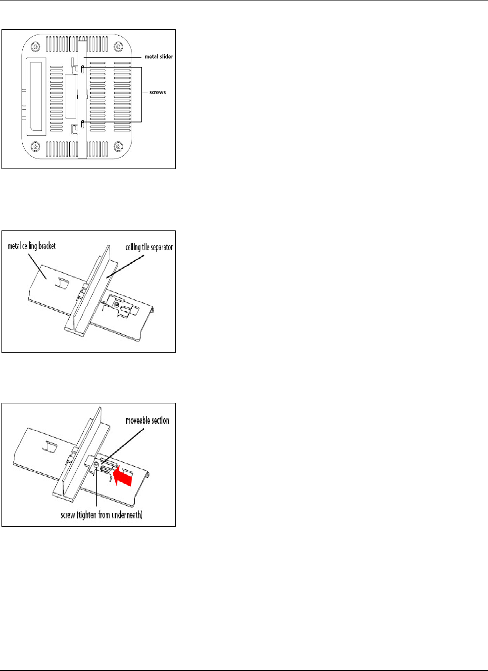
1.Attachthemetalslidertothebackofthedeviceusingthetwosmallscrews.Theslidershouldstillbeabletoslideafter
thescrewsaretightened.
Figure 5. Attaching the Metal Slider
Makesurethattheslideisleftinthesamepositionasshownabove.
Clipthemetalceilingbrackettoasuitably‐locatedceilingtileseparator.
Figure 6. Clipping the Metal Ceiling-bracket
Slidethemovablesectionintoplaceandtightenthescrew(foundunderneath)tosecureit
Figure 7. Sliding the movable section
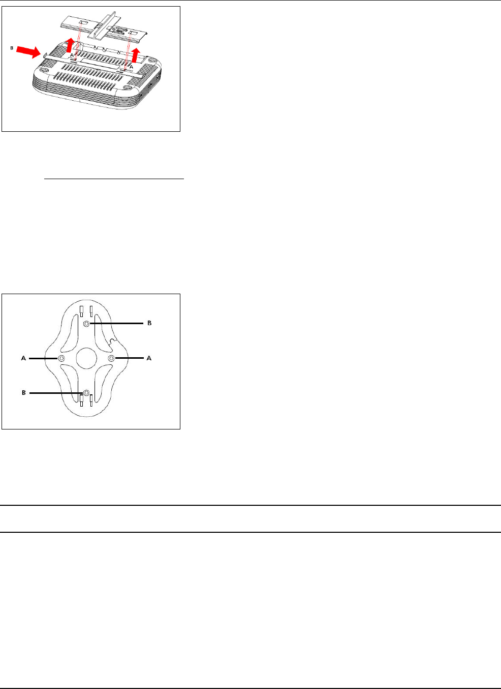
Positionthedevicesuchthatthetwotabsfromtheceilingbracketlocateintheslotsinthedevice(A),thenslidetheslider
acrosstolockthedevicetothebracket(B).
SS‐300‐AT‐C‐60InstallationGuide
Figure 8. Final positioning of the Sensor
4.2.1.2WallorElectricalBoxMounting
Toinstallthedeviceonawallorelectricalbox,usethemountingbracketthatcomeswiththedevice.Followthesesteps:
1.Followingtheseguidelines,screwthemountingbrackettoawallorelectricalbox(NEMAenclosure):
• Themountingbrackettabsshouldbepointingupward.
• Ifmountingtodrywall,usethe4screwsand4wallanchors.
• IfmountingtoanEUelectricalbox(60.3mm),use2threadedscrewsandinsertintotheholesmarked“A ” inthe
diagramshownbelow.
IfmountingtoaUSelectricalbox(83.3mm),use2threadedscrewsandinsertintotheholesmarked“B”inthediagramshown
below.
Figure 9. Holes for inserting screws
ConnecttheEthernetcable(forpowerandnetworkconnection)totheLANportonthebackofthedevice.
TomounttheSS‐300‐AT‐C‐60deviceontothemountingbracket,insertthemounting‐brackettabsintotheslotsonthebackof
theAP.
IMPORTANT:Ifyouaremountingthedeviceonawall,youcannotusetheslotsonthebottomnarrowedgeofthedevice.Instead,the
slotsonthebackofthedevicemustbeused.
ASS‐300‐AT‐C‐60devicecanbepoweredonby802.3afClass0PowerOverEthernetofNominalinputvoltage48VDC.You
canconnectthedevicetothenetworkusingPoEorapoweradapter.
4.2.2Prerequisitestoconnectthedevicetothenetwork
1.EnsurethattheServerisalreadyrunningonyournetwork.
2.AddtheDNSentry‘wifi‐security‐server’onallDNSServers.ThisentryshouldpointtotheIPaddressoftheServer.
3.EnsurethatDHCPisrunningonthesubnettowhichthedevicewillbeconnected.
SS‐300‐AT‐C‐60InstallationGuide
4.Important:IfDHCPisnotenabledonasubnet,Sensorscannotconnecttothatsubnetwithzeroconfiguration.IftheDNSentryis
notpresentontheDNSserversoryoudonothavetheDHCPserverrunningonthesubnet,youneedtoconfigurethesensor
manually.RefertoManuallyConfiguringSS‐300‐AT‐C‐60asSensorfordetailsonmanualconfigurationofSensor.
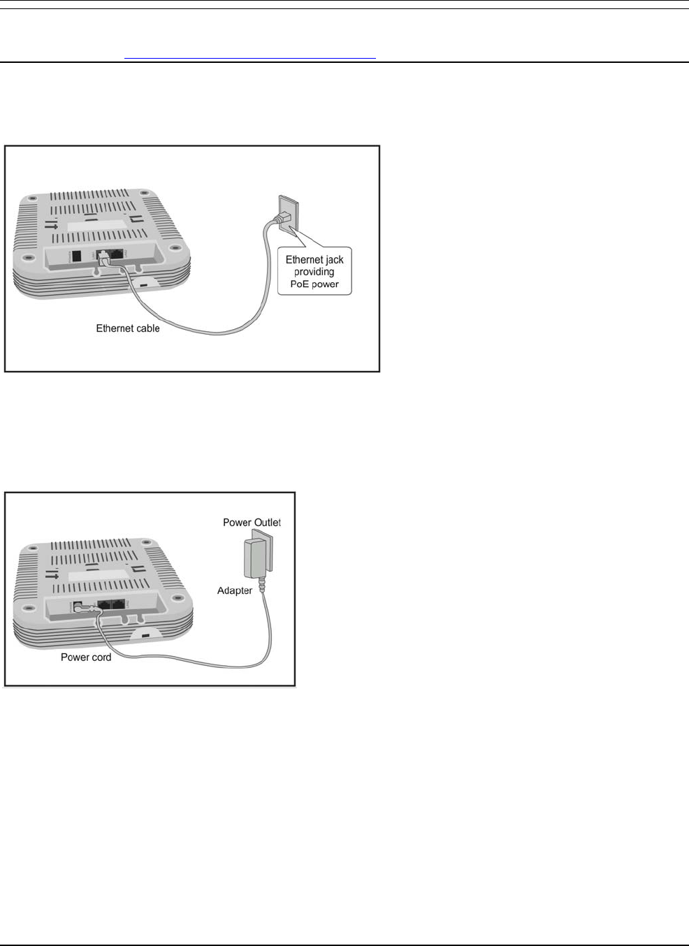
4.2.3UsingSS‐300‐AT‐C‐60withPoE
Topoweron,andconnectSS‐300‐AT‐C‐60tothenetworkusingPoE,dothefollowing.
1.ConnectoneendofthenetworkinterfacecabletotheEthernetportattherearoftheSS‐300‐AT‐C‐60device.
2.ConnecttheotherendofthenetworkinterfacecabletotheEthernetjackthatprovidesPoEpower.
Figure 10. Power up and connect SS-300-AT-C-60 using PoE
4.2.4UsingSS‐300‐AT‐C‐60withpoweradapter
Topowerupthedevice,performthefollowingsteps:
1.PlugthepowercableintotheDCpowerreceptacleattherearofthedevice.
2.Plugtheotherendofthepowercableintoan110V~240V50/60HzACpowersource.
Figure 11. Power up SS-300-AT-C-60
Waitfortwominutes!
ChecktheStatusLEDs.YouwillseeLED1turnOrangeandLED2turngreen,indicatingthattheSensorispoweredon
correctlyandwaitingtobeconnectedtothenetwork.
ToconnectSS‐300‐AT‐C‐60tothenetwork,performthefollowingsteps:
1.EnsurethatDHCPisrunningonthesubnettowhichtheSS‐300‐AT‐C‐60devicewillbeconnected.
2.ConnectoneendoftheNetworkInterfacecabletotheEthernetport(LAN1)attherearoftheSS‐300‐AT‐C‐60device
3.ConnecttheotherendoftheNetworkInterfacecabletoanEthernetjackthatisconnectedtothedesiredsubnet.
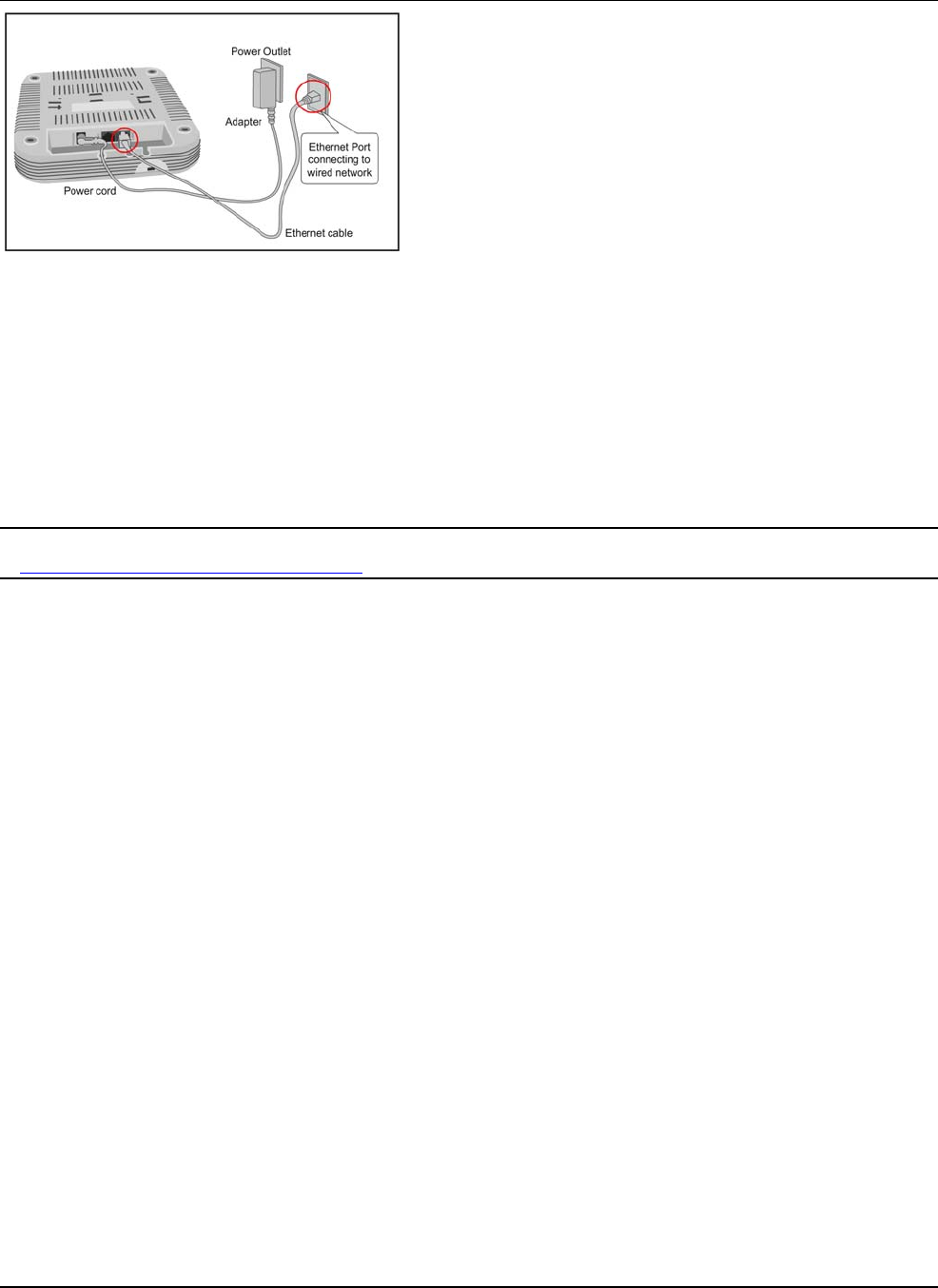
SS‐300‐AT‐C‐60InstallationGuide
Figure 12. Connect SS-300-AT-C-60 to the network
Waitfortwominutes!
ChecktheStatusLEDsonthedevice.IfallLEDsglowgreen,thenthedeviceisoperationalandconnectedtothe
SpectraGuard®Enterpriseserver.
LogontotheSpectraGuard®EnterpriseserverthroughSSH.Runthe‘getsensorlist’command.Youwillseealistofall
SensorsthatarerecognizedbytheSpectraGuard®Enterpriseserver.
TheSensorisconfiguredandreadytogo.ChecktheConsoletoensurethatthisSensorhasbeendetected.
IfalltheSensorshaveconnectedwithzeroconfiguration,youneednotreadthisinstallationguidefurther.
Note:IfLED1turnsOrange,itmeansthatthezeroconfigurationwasnotsuccessfulandtheSensormustbeconfiguredmanually.Refer
toManuallyConfiguringSS‐300‐AT‐C‐60asSensorfordetails
SS‐300‐AT‐C‐60InstallationGuide
12
Chapter5ManuallyConfiguringtheSS‐300‐AT‐C‐60asSensor
Important:IftheinstallationinInstallingSS‐300‐AT‐C‐60wassuccessful,stop!Youdonotneedtoconfigurethedevicemanually.
5.1Introduction
ManualconfigurationofSS‐300‐AT‐C‐60asaSensoristypicallyrequiredinthefollowingcases:
• DeviceneedstobeconfiguredinNDmode.
• SensorOnly(SO)devicescannotconnecttotheSpectraGuard®Enterpriseserverthroughzeroconfiguration.The
DNSentryfortheSpectraGuard®Enterpriseserverhasbeenchangedtoanentryotherthanʺwifi‐security‐serverʺor
thereisnoDNSServerpresentinthenetwork.Thisisapplicableformulti‐serverinstallations.
• SensorisplacedonasubnetthatisnotDHCPenabled.
5.2ConfiguringSensorthroughConfigShell
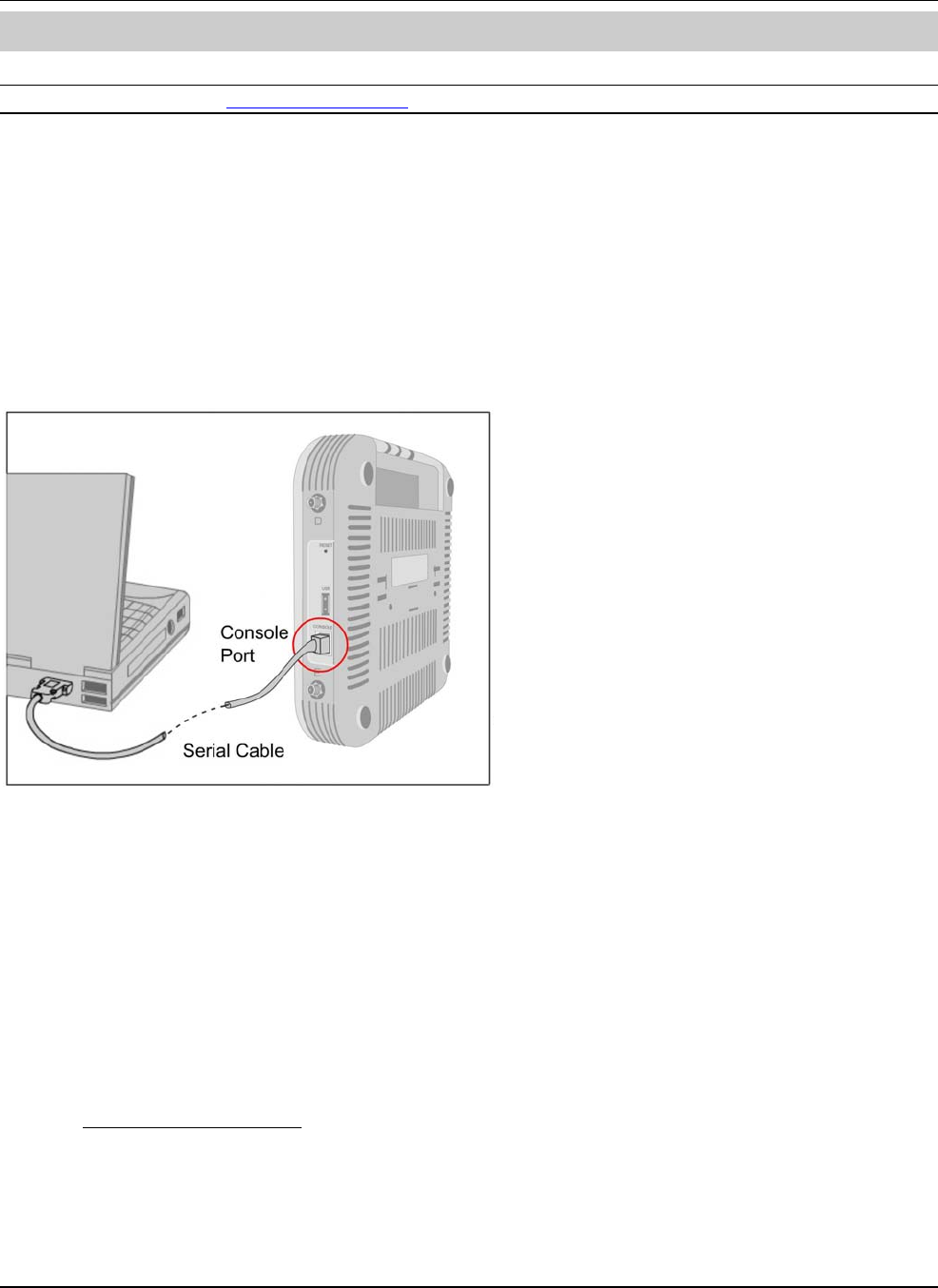
TousetheConfigShell,connectaSerial(RS‐232)cablebetweenyourcomputerandtheSensor.TheConfigShellsupportsa
pre‐definedsetofcommandsusedtoconfiguretheSensor.
Figure 13. Connecting SS-300-AT-C-60 to your computer using a Serial Cable
ThestepstoconfiguretheSensormanuallyareasfollows:
1.InvokeHyperTerminal(orminicom)
Loginandchangethedefaultpassword
SetServerDiscovery
SetSensorMode
SetNetworkSettingsforthatSensorMode
Theabovestepsareexplainedindetailbelow.
5.2.1InvokeHyperTerminal(orminicom)
ToconfiguretheSensor,followthestepsdescribedbelowtoinvoketheConfigShell.
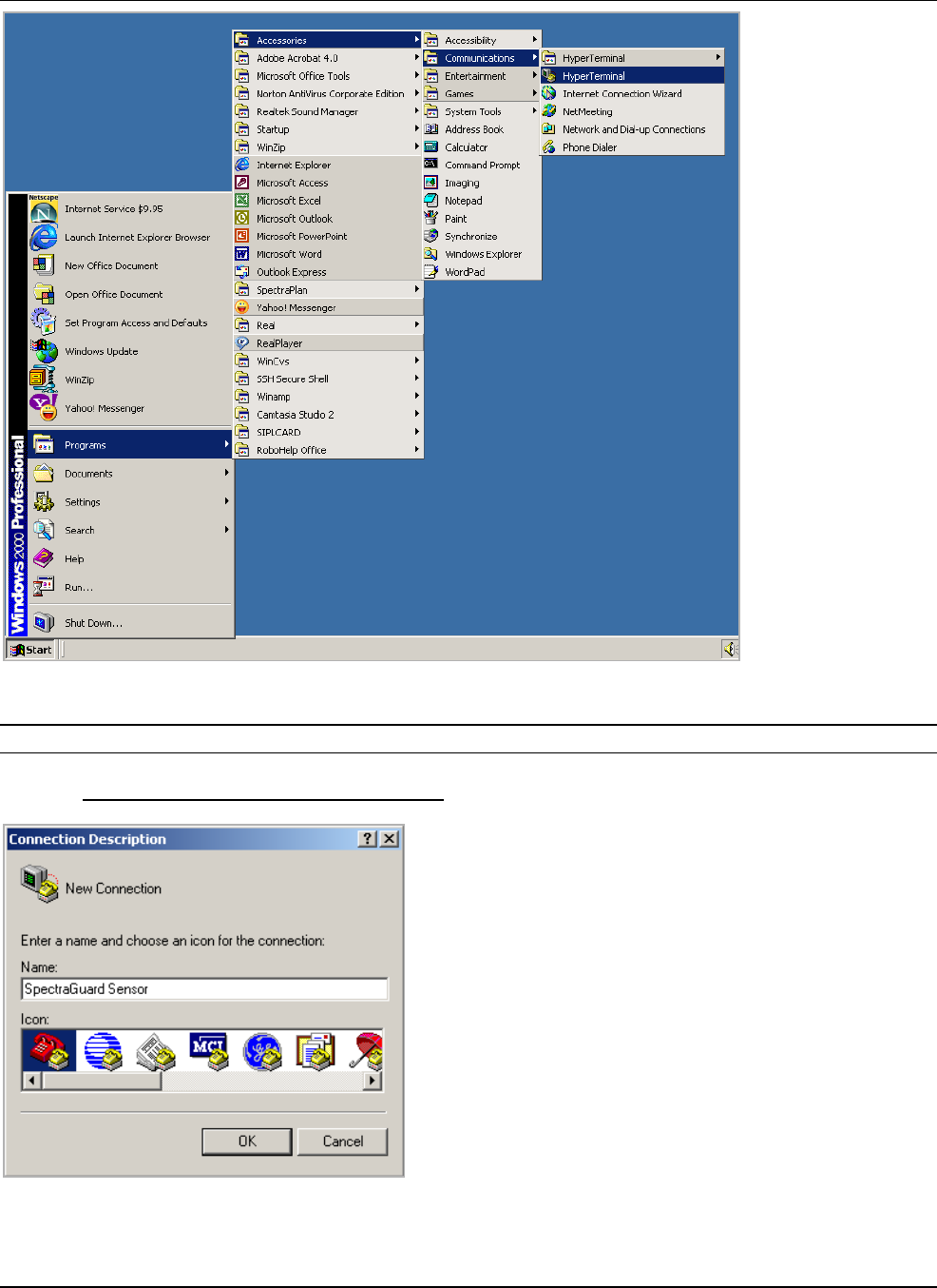
5.2.1.1LaunchingHyperTerminal
TostartHyperTerminal,clickStartProgramsAccessoriesCommunicationsHyperTerminalasshowninthefollowing
figure.
SS‐300‐AT‐C‐60InstallationGuide
Figure 14. Opening HyperTerminal
Note:IfyouareusingaLinuxlaptop,youcanuseminicomtoconnecttotheConfigShell.
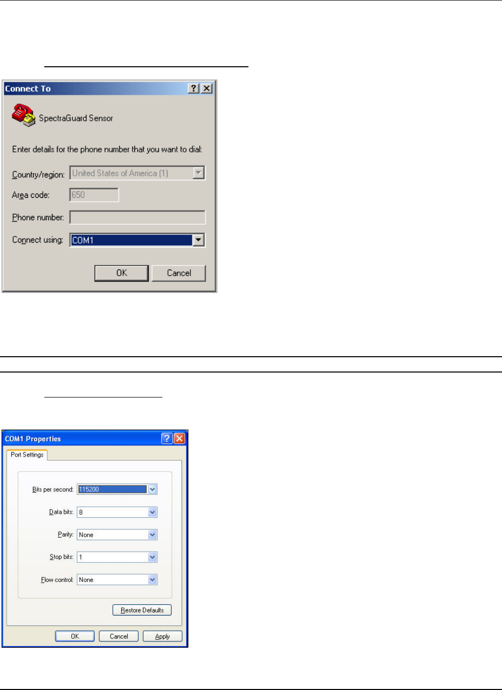
5.2.1.2DefiningaNewHyperTerminalConnection
Figure 15. Define a New HyperTerminal Connection for Sensor
SS‐300‐AT‐C‐60InstallationGuide
• Selectanicontoidentifythenewconnection.
• TypetherequirednamefortheHyperTerminalconnectionintheNamefield
Click<OK>ontheConnectionDescriptiondialog.
5.2.1.3SpecifyingHyperTerminalConnectionDetails
Figure 16. Specify HyperTerminal Connection Details
• Selectorentertheappropriateconnectiondetails.
Click<OK>ontheConnectTodialog.
Note:Thenameoftheserialportwillchangeasperthesettingsofyourcomputer.
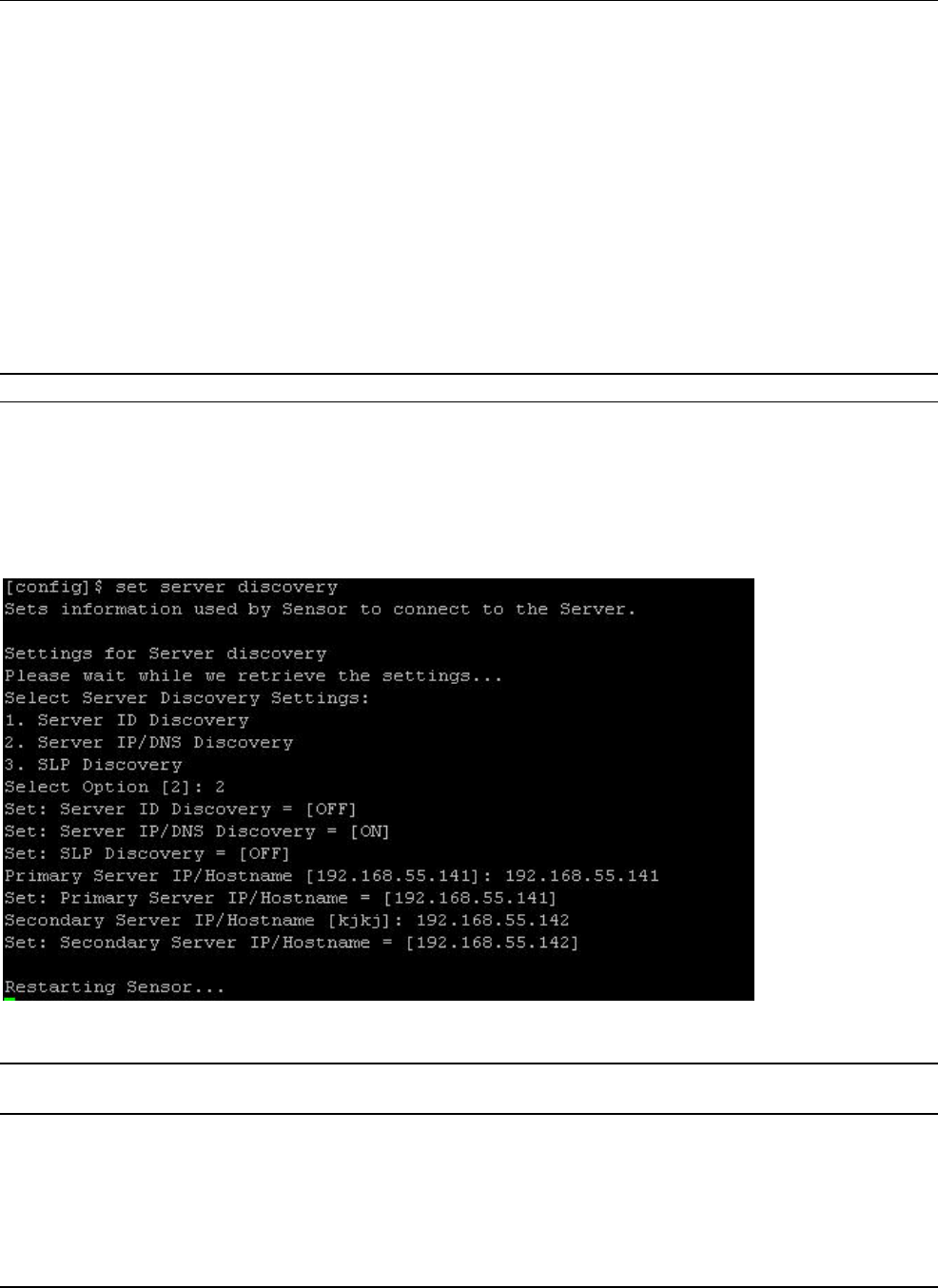
5.2.1.4EditingSerialPortSettings
SensorSS‐300‐AT‐C‐60
SS‐300‐AT‐C‐60InstallationGuide
Figure 17. Edit Serial Port Settings for Sensor SS-300-AT-C-60
• Edittheserialportsettingsasfollowsorclick<RestoreDefaults>toensurepropercommunicationbetweenthe
Sensorandyourcomputer.
Bitspersecond:115200
Databits:8
Parity:None
Stopbits:1
Flowcontrol:None
• Click<OK>ontheCOMPropertiesdialog.
Press<Enter>or<Space>ontheHyperTerminalscreen.
5.2.2LoginandChangetheDefaultPassword
LogintotheConfigShellusingtheusernameconfigandpasswordconfig.Changethedefaultpasswordusingthecommand
passwd.YoucanchangetheSensorpasswordusingSensortemplates.Refertosection8.4.4:SensorConfigurationinthe
SpectraguardEnterpriseUserGuideformoredetails.
Recommended;AirTightrecommendsthatyouchangethedefaultpasswordforsecurityreasons,althoughitisnotmandatory.
5.2.3SetServerDiscovery
ThenextstepistosettheServerDiscoveryinformation.TherearetwotypesofServerDiscovery.
• ServerIPbaseddiscovery(preferred)
• ServerIDbaseddiscovery(deprecated)
ServiceLocationProtocol(SLP)baseddiscovery(ifwifi‐security‐serverservicehasbeenconfigured)
UsethecommandsetserverdiscoverytopointtheSensortothecorrectServer.
Figure 18. set server discovery command
Note:IfIP/HostnamebaseddiscoveryisbeingusedandthereismorethanoneServeronthenetwork,thenyoumustentertheIPaddress
oftheappropriateServer.
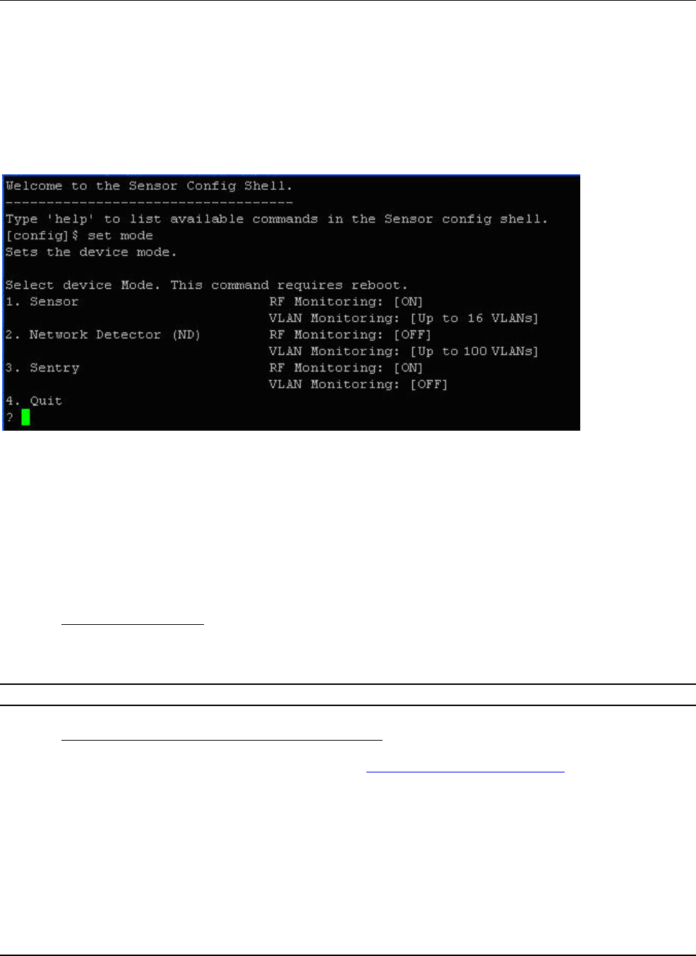
5.2.4SetSensorMode
ThenextstepistosetthemodeoftheSensor.Therearetwopossiblemodes:
SS‐300‐AT‐C‐60InstallationGuide
• SensorMode:Thisisthedefaultmode.Inthismode,thedeviceshouldbeconnectedintoatrunkport(802.1Q
capable)onaswitch.ItthenmonitorsmultipleVLANsthatareconfiguredonthattrunkportandarechosenbythe
userusingtheNDCLI.ThewirelessinterfaceoftheSensorisenabled.Similarly,anSS‐300‐AT‐C‐60canmonitorupto
16VLANs.
• NDMode:Thismodeneedstobeexplicitlyconfigured.Inthismode,thedeviceshouldbeconnectedintoatrunk
port(802.1Qcapable)onaswitch.ItthenmonitorsmultipleVLANsthatareconfiguredonthattrunkportandare
chosenbytheuserusingtheNDCLI.ThewirelessinterfaceoftheNDisdisabled.ASS‐300‐AT‐C‐60functioningasa
WIPSsensorcandetectandmonitorupto100VLANs.
• UsethesetmodecommandtosetthedevicemodeforSS‐300‐AT‐C‐60.
Figure 19. set sensor mode command for SS-300-AT-C-60
5.2.5ConfigureNetworkSettings
Oncethemodeisset,youhavetoenabletheNetworkSettings.
NetworkDetector/SensorMode:Forthismode,usethecommandsetvlanconfig.ThiscommandconfigurestheIPaddresses
ontheND.
RefertoChapter3:GuidelinesforConfiguringandInstallingNDinthedocument‘NetworkDetectorConfigurationfor
SpectraGuardEnterprise_6.7Update1’forfurtherdetails.
5.2.5.1ConfigureIPv6settings
SS‐300‐AT‐C‐60isIPv6capable.Usethecommandsetipv6configtoconfigureadvancedoptionssuchasDHCPsettings,auto
negotiationandmanualconfiguration.
Note:IPv6settingsarenotsupportedintheSS‐200‐ATsensorsHowtoconfigureCommunicationkeyorPassphrase
5.2.5.2HowtoconfigureCommunicationKeyorPassphrase
ToconfigurethecommunicationkeyorpassphrasekindlyrefertoAppendixA:MutualAuthenticationfordetails.

SS‐300‐AT‐C‐60InstallationGuide
1
7
Chapter6SS‐300‐AT‐C‐60ConfigShellCommands
ThefollowingtablesdetailtheSS‐300‐AT‐C‐60configshellcommands.
Table1.getcommands
get Commands
Command Description
get ap Displays all the currently visible APs
get interface Displays Network Interface speed and mode
get ip config
(deprecated) Displays the IP information
get log Displays the log information as it is created
get log config Displays the configuration of the logger
get mode Displays the mode in which the Sensor is currently configured
get rf Displays if RF monitoring for a Sensor is ‘ON’ or ‘OFF’
get serial num Displays the Board Number
get server discovery Displays the Server discovery/setting information
get status Displays the current running status of all the components
get version Displays the version and build information of all the components
get vlan config Displays listing of VLANs which are configured for monitoring by ND or Sensor
get vlan id Displays listing of all VLANs which can be detected by ND or Sensor
get vlan status Displays status of VLANs which are configured for monitoring by ND or Sensor
get model Displays the Sensor Model
get antenna Displays antenna configuration (Internal/ External)
Table2.setcommands
set Commands
Command Description
set erase Sets the erase character to ^H.
set interface Sets Network Interface properties like auto negotiation, speed, and duplex settings.
set ip config Runs through the current VLAN and IP config wizard.
set server discovery Sets the Server discovery information.

SS‐300‐AT‐C‐60InstallationGuide
18
set vlan config Configures list of VLANs and their network settings, to be monitored by ND or Sensor.
set ipv6 config Sets IPv6 network settings.
set mode Sets the mode to Sensor,Network Detector, or Sentry.
set communication key Sets the Sensor-Server shared secret. You need to enter a hexadecimal value, of length
32, as the shared secret. It can be used instead of the ‘set communication passphrase’
command. Use this command if you are comfortable working with hexadecimals.
set communication
passphrase Sets the Sensor-Server shared secret. You need to enter a character string, of length
between 10 and 127, as the shared secret. The string is internally converted to
hexadecimal format. It can be used instead of the‘set communication key’ command.
Table3.Miscellaneouscommands
Other Commands
Command Description
exit Exists the Sensor config Shell session
help Displays help for all commands
help set Displays help for ‘set’ commands
help get Displays help for ‘get’ commands
help other Displays help for ‘other’ commands
passwd Changes the config Shell password
ping <Hostname/IP
address> Pings a host.
Usage: ping <IP_address/host_name> e.g. ping 192.168.1.246
ping6 <IPv6 address or
hostname> Pings an IPv6 host
Usage: ping6 <IPv6_address/host_name>
reboot Reboots the Sensor
restart Restarts the Sensor application
reset factory Resets the Sensor to ‘out of the box’ status
upgrade Upgrades the Sensor manually from a given IP address

SS‐300‐AT‐C‐60InstallationGuide
19
Chapter7SS‐300‐AT‐C‐60Troubleshooting
FollowingarethetroubleshootingguidelinesforSS‐300‐AT‐C‐60inAPmode.
FollowingarethetroubleshootingguidelinesforSS‐300‐AT‐C‐60insensormode.
Symptoms Diagnosis Solution
LED1: Solid Orange
LED4: Fast Blink The AP did not receive
a valid IP address via
the DHCP.
The DHCP Server is unreachable. Restore the connectivity
to the DHCP Server or set a static IP address via the HTTP
interface or the Config Shell CLI.
LED1: Solid Orange
LED4: Slow Blink
Unable to connect to
the Server.
Ensure that the Server is running and is reachable from the
network to which the AP is attached. If there is a firewall or
a router with ACLs enabled between the AP and the Server,
ensure that the traffic is allowed on UDP port 3851.
If utilizing the Server ID based discovery, ensure that
multicast is enabled on the network.
Alternatively, if utilizing the Server IP based discovery,
ensure that the DNS name ‘wifi-security-server’ has been
correctly entered on the DNS Server. Also ensure that the
DNS Server IP addresses are either correctly configured on
the AP, or are provided by the DHCP Server.
It is also possible that the AP is unable to connect to the
Server because it has failed to authenticate with the
Server. If this is the case, there will be an 'Authentication
failed for AP's event raised on the Server. Refer to the
Event for recommended action.
LED1: Solid Orange
LED4: Solid Green The Ethernet cable is
loose. It is probably
disconnected from the
network.
Ensure that the Ethernet cable is connected.
LED1: Solid Orange
LED3: Solid Green A fatal Software error
has occurred. Contact support@airtightnetworks.com for more details.

SS‐300‐AT‐C‐60InstallationGuide
20
Symptoms Diagnosis Solution
LED1: Solid Orange
LED4: Fast Blink The Sensor did not
receive a valid IP
address via the DHCP.
The DHCP Server is unreachable. Restore the connectivity
to the DHCP Server or set a static IP address via the HTTP
interface or the Config Shell CLI.
LED1: Solid Orange
LED4: Slow Blink
Unable to connect to
the Server.
Ensure that the Server is running and is reachable from the
network to which the Sensor is attached. If there is a
firewall or a router with ACLs enabled between the Sensor
and the Server, ensure that the traffic is allowed on UDP
port 3851.
If utilizing the Server ID based discovery, ensure that
multicast is enabled on the network.
Alternatively, if utilizing the Server IP based discovery,
ensure that the DNS name ‘wifi-security-server’ has been
correctly entered on the DNS Server. Also ensure that the
DNS Server IP addresses are either correctly configured on
the Sensor, or are provided by the DHCP Server.
It is also possible that the Sensor is unable to connect to
the Server because it has failed to authenticate with the
Server. If this is the case, there will be an 'Authentication
failed for Sensor's event raised on the Server. Refer to the
Event for recommended action.
LED1: Solid Orange
LED4: Solid Green The Ethernet cable is
loose. It is probably
disconnected from the
network.
Ensure that the Ethernet cable is connected.
LED1: Solid Orange
LED2: Solid Green An error on the 802.11
interface has occurred. Contact support@airtightnetworks.com for more details.
LED1: Solid Orange
LED3: Solid Green A fatal Software error
has occurred. Contact support@airtightnetworks.com for more details.

SS‐300‐AT‐C‐60InstallationGuide
21
Chapter8AppendixA:ServerSensorMutualAuthentication
TheSensor‐ServercommunicationbeginswithamutualauthenticationstepinwhichtheSensorandServerauthenticateeach
otherusingasharedsecret.Sensor‐Servercommunicationtakesplaceonlyifthisauthenticationsucceeds.
Onceauthenticationsucceeds,asessionkeyisgenerated.AllcommunicationbetweentheSensorandServerfromthispoint
onisencryptedusingthesessionkey.
TheSensorandServerareshippedwiththesamedefaultvalueofthesharedsecret.TheCLIcommandsareprovidedonboth
ServerandSensorforchangingthesharedsecret.
Note:Oncethesharedsecret(communicationkey)ischangedontheServer,allSensorsconnectedtotheServerwillautomaticallybe
setuptousethenewcommunicationkey.SensorsthatarenotconnectedtotheServeratthistimewillneedtobesetupwiththesame
communicationkeyforthemtobeabletocommunicatewiththisServer.
Note:WhiletheServerisbackwardcompatible,thatis,preversion6.7Update1Sensorscanconnecttoaversion6.7Update1Server,this
isnotrecommended.OnceallSensorshavebeenupgradedtoversion6.7Update1,thesetsensorlegacyauthentication
CLIcommand
canbeusedtodisableolderSensorsfromconnectingtotheServer.