Array Solutions Array Solutions A600S Amateur Radio Linear Amplifier User Manual A600S User Operational Manual
Array Solutions dba Array Solutions Amateur Radio Linear Amplifier A600S User Operational Manual
UserManual.wiki
>
Array Solutions Array Solutions
>
A600S User Manual
A600S User Operational Manual
Navigation menu
Upload a User Manual
Namespaces
Wiki Guide
HTML
PDF
Info
Views
User Manual
Discussion / Help
Navigation
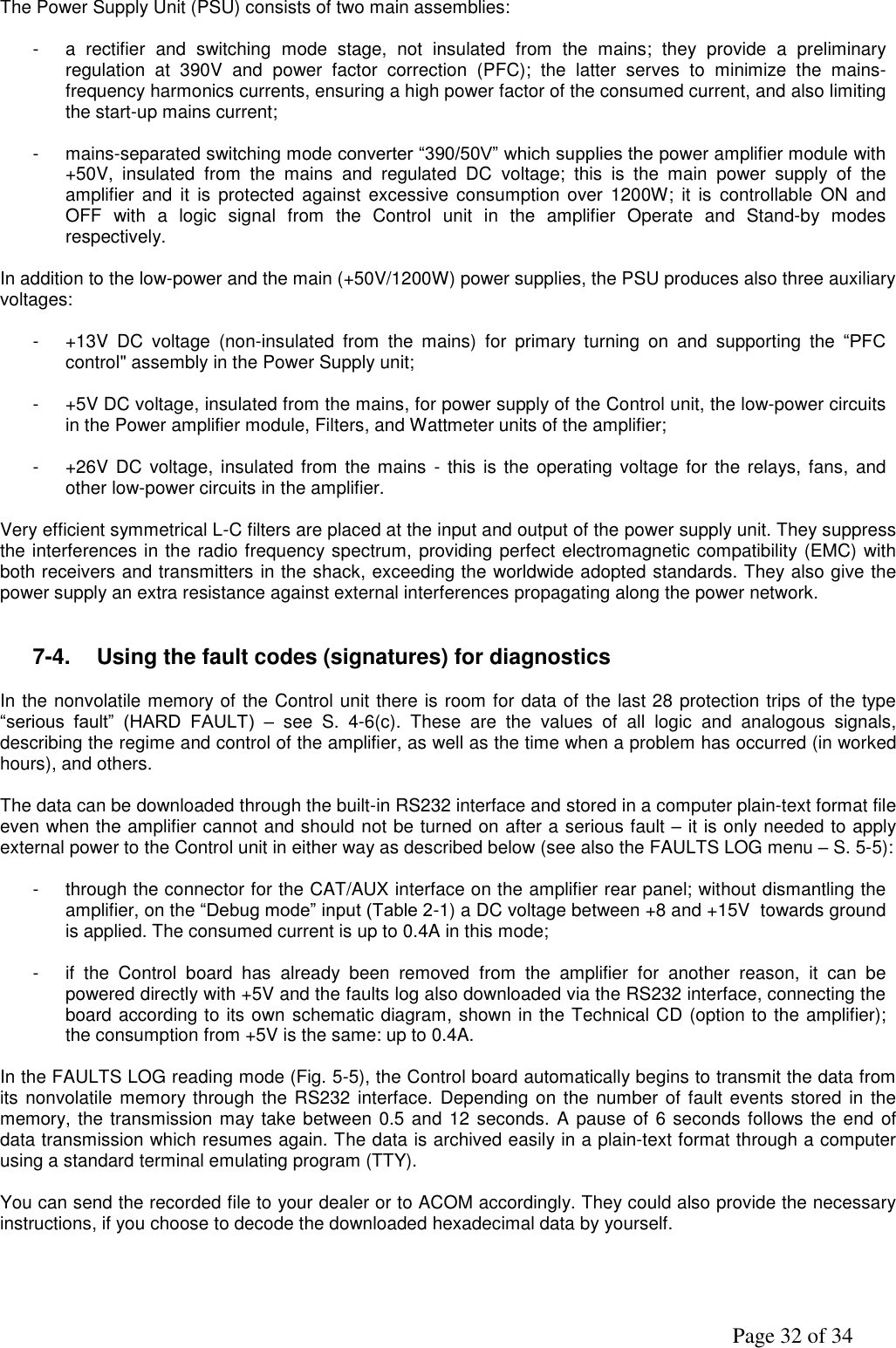
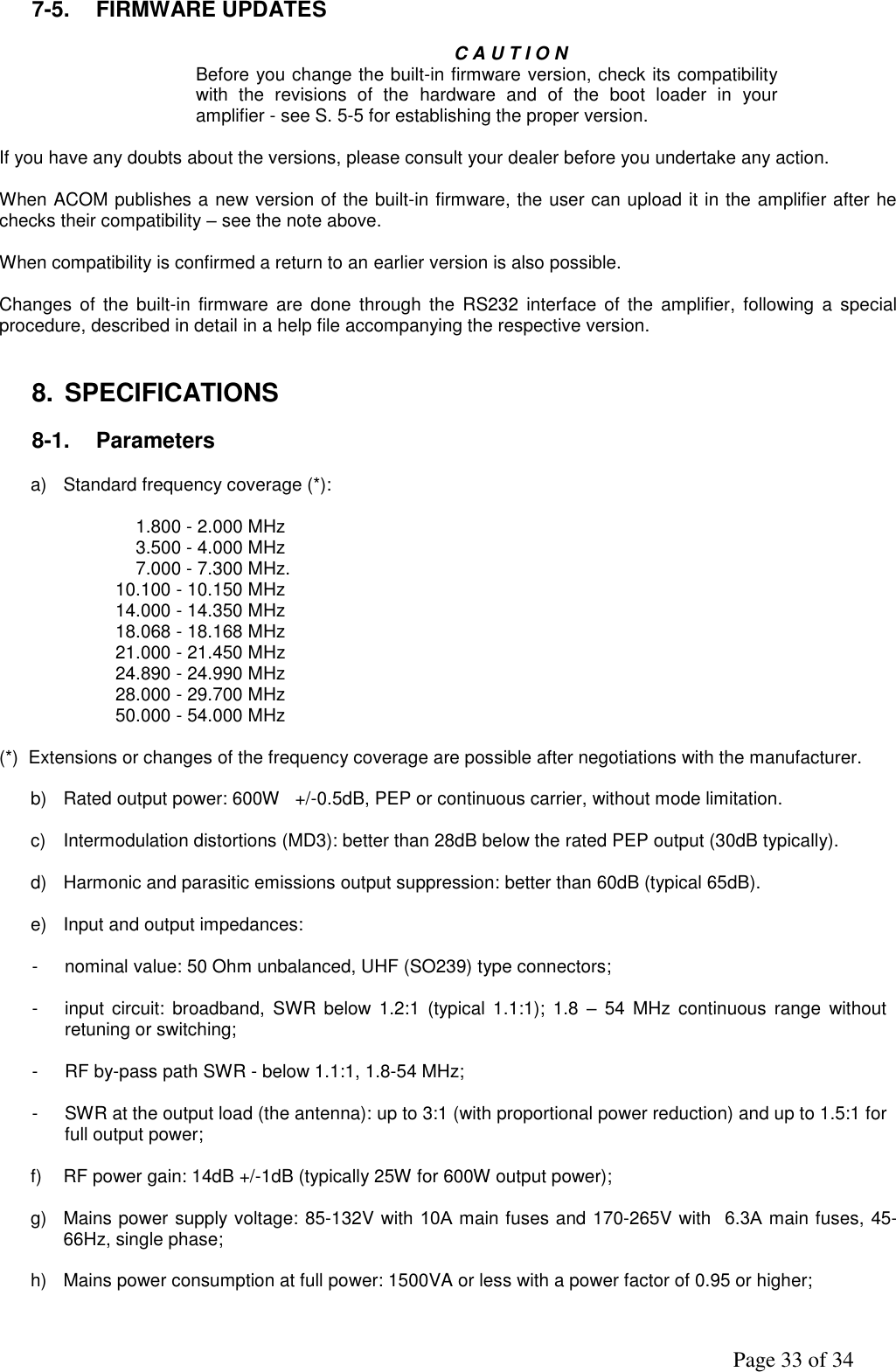
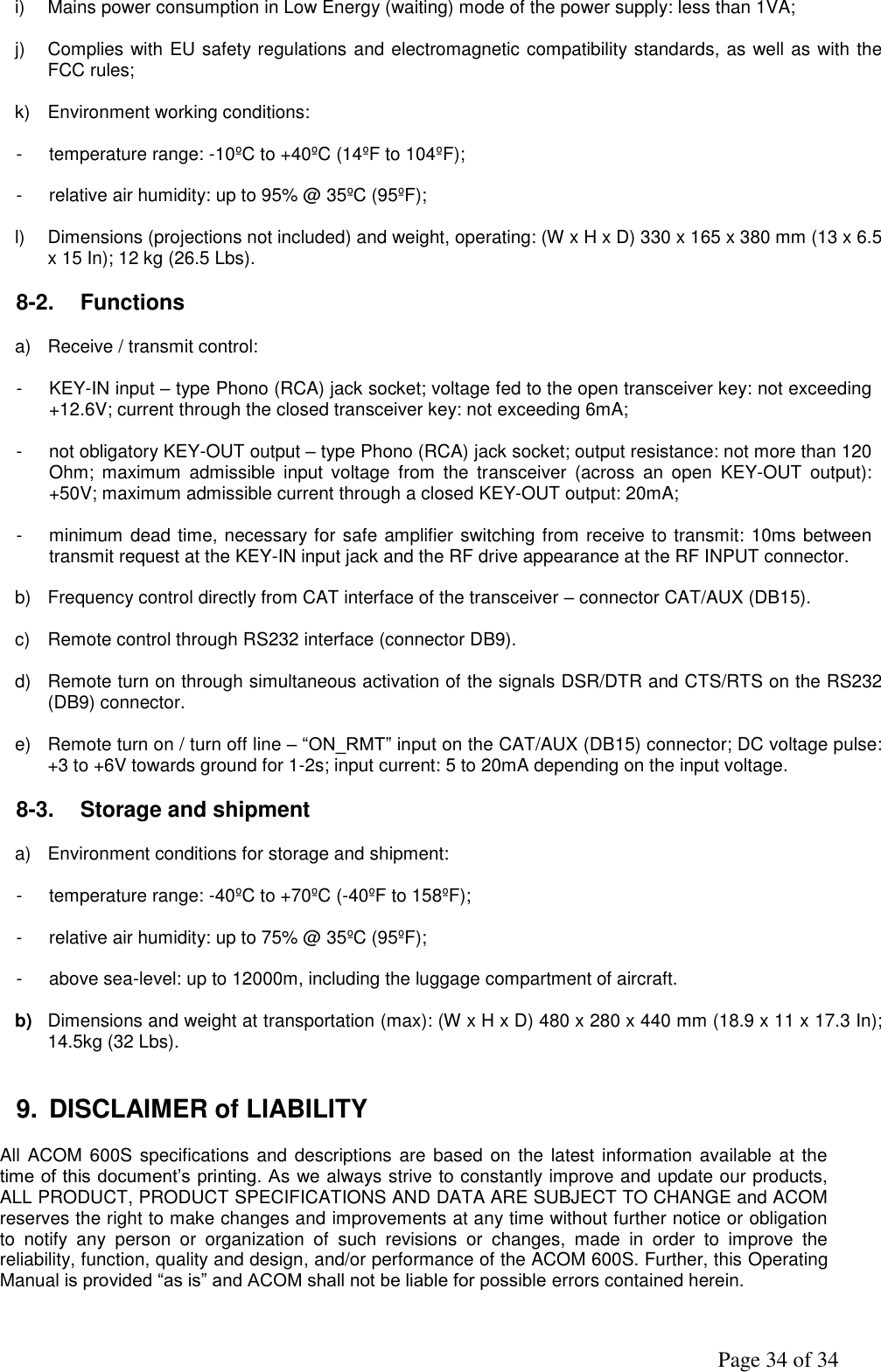
![Page 23 of 34 Fig. 5.2 Menu “Service functions in the amplifier” – AMP SERVICE 5-3. Menu “Selection of CAT/AUX interface” – CAT/AUX SETTINGS The type and parameters of the CAT/AUX interface for your transceiver are assigned here. If your transceiver has no CAT interface control, nor parallel or analog voltage output (BCD / VOLTAGE BAND DATA), you should select [OFF] at the uppermost row which will disable the amplifier CAT/AUX interface. Fig. 5-3 Menu “Selection of CAT/AUX interface” – CAT/AUX SETTINGS](https://usermanual.wiki/Array-Solutions-Array-Solutions/A600S/User-Guide-2204470-Page-23.png)