Avalan Wireless Systems orporated AW5802MR AW5802MR User Manual FCC Part 15
Avalan Wireless Systems Incorporated AW5802MR FCC Part 15
UserManual.wiki
>
Avalan Wireless Systems orporated
>
AW5802MR User Manual
Manual
Navigation menu
Upload a User Manual
Namespaces
Wiki Guide
HTML
PDF
Info
Views
User Manual
Discussion / Help
Navigation
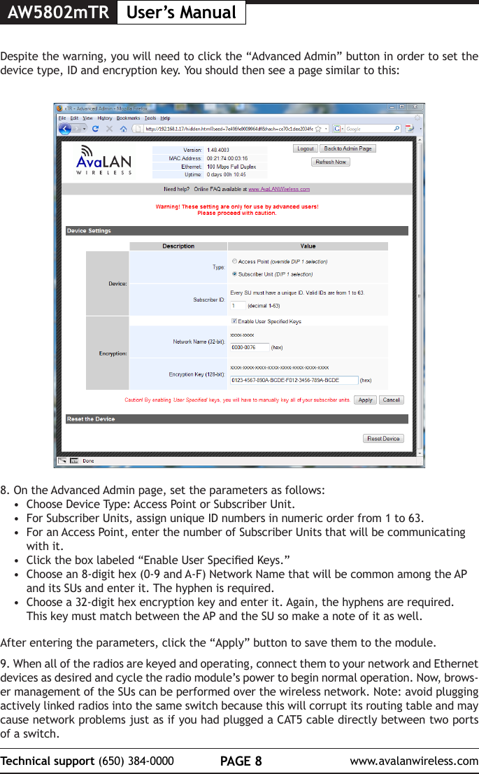
![PAGE 7Technical support (650) 384-0000 www.avalanwireless.comUser’s Manual AW5802mTR7. The admin page has sections similar to the login page showing radio statistics and device information plus it adds several new sections. The Device Settings section allows setting the network information and choosing an RF frequency channel. The default is to allow the radio to choose its own frequency based on minimizing interference. If you set a xed channel, make sure the AP and all SUs use the same one. References to DIPs on this and the next web page refer to the DIP switches on the module that are used in the “easy key” method of con-guration and may be ignored when using the browser method.If you scroll down in the Admin browser page, you will come to three more sections:• A graphical spectrum analyzer display that may help you to select radio channels that avoid interference• A section to be used if an update to the AW5802mTR’s rmware is required• An Advanced Links section with a dire warning about advanced users only.5. Make note of the chosen IP address and password, then click “Go to Device Web Page.” This will cause your default web browser to launch with the device IP address in the browser address bar. Or you may launch the browser on your own and enter the web page address manually: http://[the IP address you just set]. 6. The browser page that loads rst shows the current device information and QoS statistics and provides a login at the upper right. Log in using the password you just specied (or “pass-word” if you kept the default). If the login succeeds, you will see an admin page similar to this:](https://usermanual.wiki/Avalan-Wireless-Systems-orporated/AW5802MR/User-Guide-1862250-Page-8.png)