Avalan Wireless Systems orporated AW900G2LP MOD090-LP User Manual
Avalan Wireless Systems Incorporated MOD090-LP
UserManual.wiki
>
Avalan Wireless Systems orporated
>
AW900G2LP User Manual
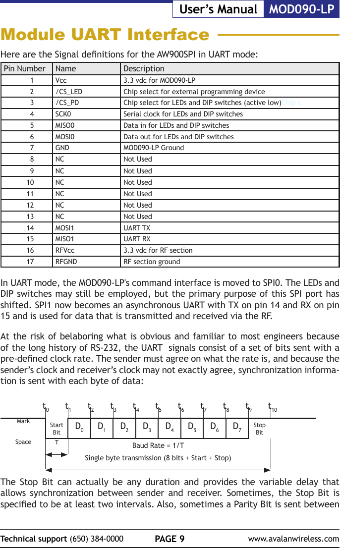
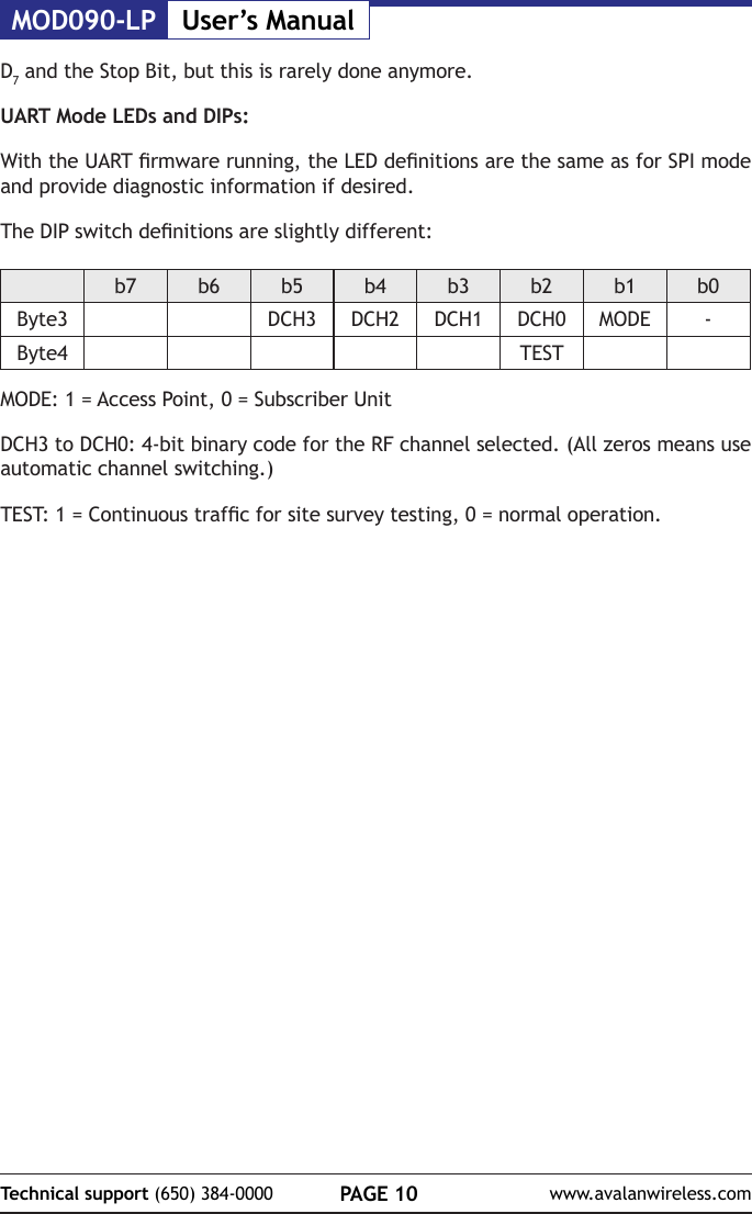
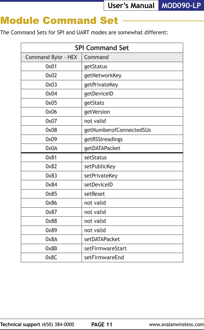
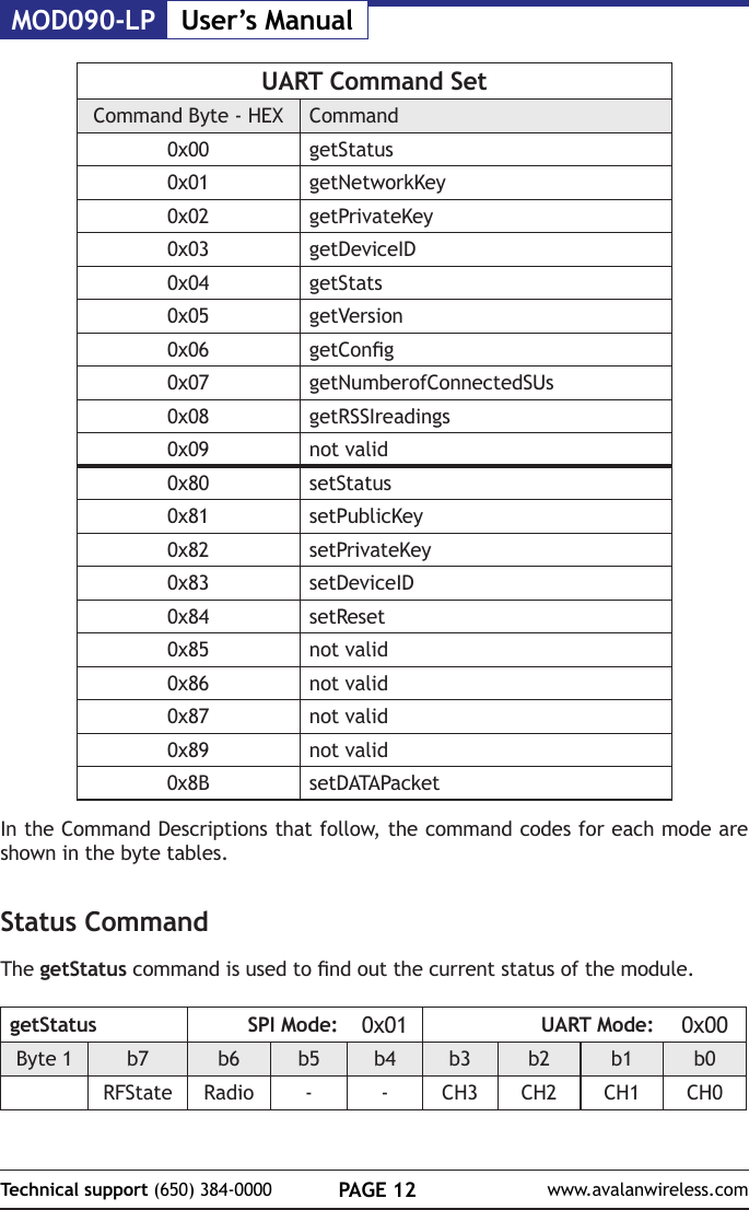
User Manual
Navigation menu
Upload a User Manual
Namespaces
Wiki Guide
HTML
PDF
Info
Views
User Manual
Discussion / Help
Navigation
![PAGE 31Technical support (650) 384-0000 www.avalanwireless.comMOD090-LPUser’s ManualWARNING: WARNING: The FCC requires that all spread spectrum devices operating within the Unlicensed radio frequency bands must limit themselves to a maximum radiated power of 4 Watts EIRP. Failure to observe this limit is a violation of our warranty terms, and shall void the user’s authority to operate the equipment. This can be stated as follows:RF power - cable loss + antenna gain <= 36 dBm EIRPFixed Base Station and Mobile ApplicationsAvaLAN Modules are pre-FCC approved for use in xed base station and mobile applications. When the antenna is mounted at least 21.05 cm (8”) from nearby persons, the application is considered a mobile application.Portable Applications and SAR TestingWhen the module will be used closer than 21.05 cm to nearby persons, then the application is considered “portable” and requires an additional test be performed on the nal product. This test is called the Specic Absorption Rate (SAR) testing and measures the emissions from the module and how they affect the person.RF Exposure(This statement must be included as a CAUTION statement in OEM product manuals.) WARNING: This equipment is approved only for mobile and base station transmitting devices. Antenna(s) used for this transmitter must be installed to provide a separation distance of at least 21.05 cm from all persons and must not be co-located or operating in conjunction with any other antenna or transmitter.To fulll FCC Certication requirements:1. Integrator must ensure required text [Figure 1] is clearly placed on the outside of the nal product.2. AW900G2LP Module may be used only with Approved Antennas that have been tested with this module. IC RSS-102 RF Exposure statement:This system has been evaluated for RF Exposure per RSS-102 and is in compliance with the limits specied by Health Canada Safety Code 6. The system must be installed at a minimum separation distance from the antenna to a general bystander of 31.2 cm to maintain compliance with the General Population limits.L’exposition aux radiofréquences de ce système a été évaluée selon la norme RSS-102 et est jugée conforme aux limites établies par le Code de sécurité 6 de Santé Canada. Le système doit être installé à une distance minimale de 31.2 cm séparant l’antenne d’une personne présente en conformité avec les limites permises d’exposition du grand public.Antenna Pattern Type GainOmni directional Monopole ≤ 6dBiDirectional Yagi ≤ 15dBiDirectional Panel ≤ 10dBiType certied AntennasIC (Industry Canada) CerticationThis device complies with Industry Canada licence-exempt RSS standard(s). Operation is subject to the following two conditions: (1) this device may not cause interference, and (2) this device must accept any interference, including interference that may cause undesired operation of the device.Le présent appareil est conforme aux CNR d'Industrie Canada applicables aux appareils radio exempts de licence. L'exploitation est autorisée aux deux conditions suivantes: (1) l'appareil ne doit pas produire de brouillage, et (2) l'utilisateur de l'appareil doit accepter tout brouillage radioélectrique subi, même si le brouillage est susceptible d'en compromettre le fonctionnement.Contains Model AW900G2LP Radio, IC: 5303A-AW900G2LPIntegrator is responsible for its product to comply with IC ICES-003 & FCC Part 15, Sub. B - Unintentional Radiators. ICES-003 is the same as FCC Part 15 Sub. B and Industry Canada accepts FCC test report or CISPR 22 test report for compliance with ICES-003.Transmitters with Detachable Antennas This radio transmitter (IC: 1846A-XLRP) has been approved by Industry Canada to operate with the antenna types listed in AW900G2LP Approved Antennas abov with the maximum permissible gain and required antenna impedance for each antenna type indicated. Antenna types not included in this list, having a gain greater than the maximum gain indicated for that type, are strictly prohibited for use with this device.Le présent émetteur radio (IC: 1846A-XLRP) a été approuvé par Industrie Canada pour fonctionner avec les types d'antenne énumérés ci?dessous et ayant un gain admissible maximal et l'impédance requise pour chaque type d'antenne. Les types d'antenne non inclus dans cette liste, ou dont le gain est supérieur au gain maximal indiqué, sont strictement interdits pour l'exploitation de l'émetteur.Detachable AntennaUnder Industry Canada regulations, this radio transmitter may operate using only an antenna of a type and maximum (or lesser) gain approved for the transmitter by Industry Canada. To reduce potential radio interference to other users, the antenna type and its gain should be so chosen that the equivalent isotropically radiated power (e.i.r.p.) is not more than that necessary for successful communication.Conformément à la réglementation d'Industrie Canada, le présent émetteur radio peutfonctionner avec une antenne d'un type et d'un gain maximal (ou inférieur) approuvépour l'émetteur par Industrie Canada. Dans le but de réduire les risques de brouillageradioélectrique à l'intention des autres utilisateurs, il faut choisir le type d'antenne etson gain de sorte que la puissance isotrope rayonnée équivalente (p.i.r.e.) ne dépassepas l'intensité nécessaire àl'établissement d'une communication satisfaisante.](https://usermanual.wiki/Avalan-Wireless-Systems-orporated/AW900G2LP/User-Guide-3329580-Page-31.png)