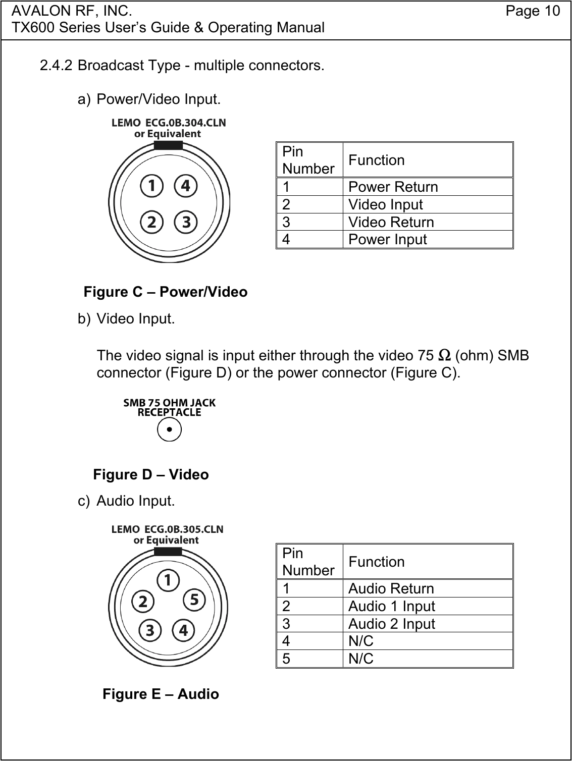
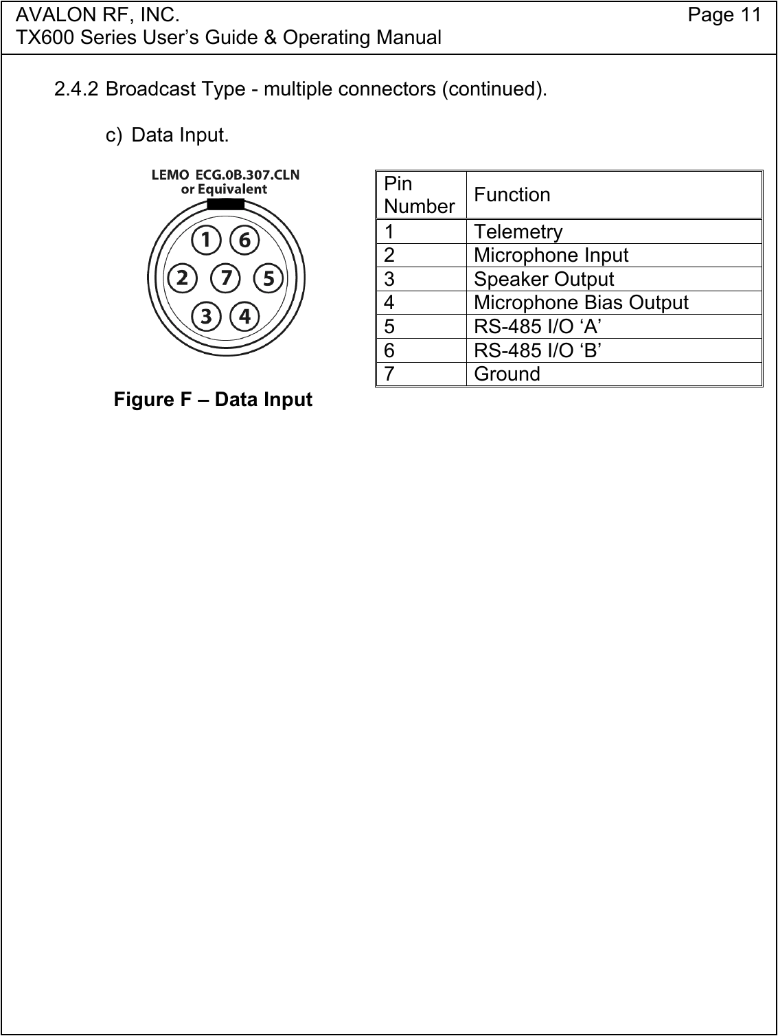
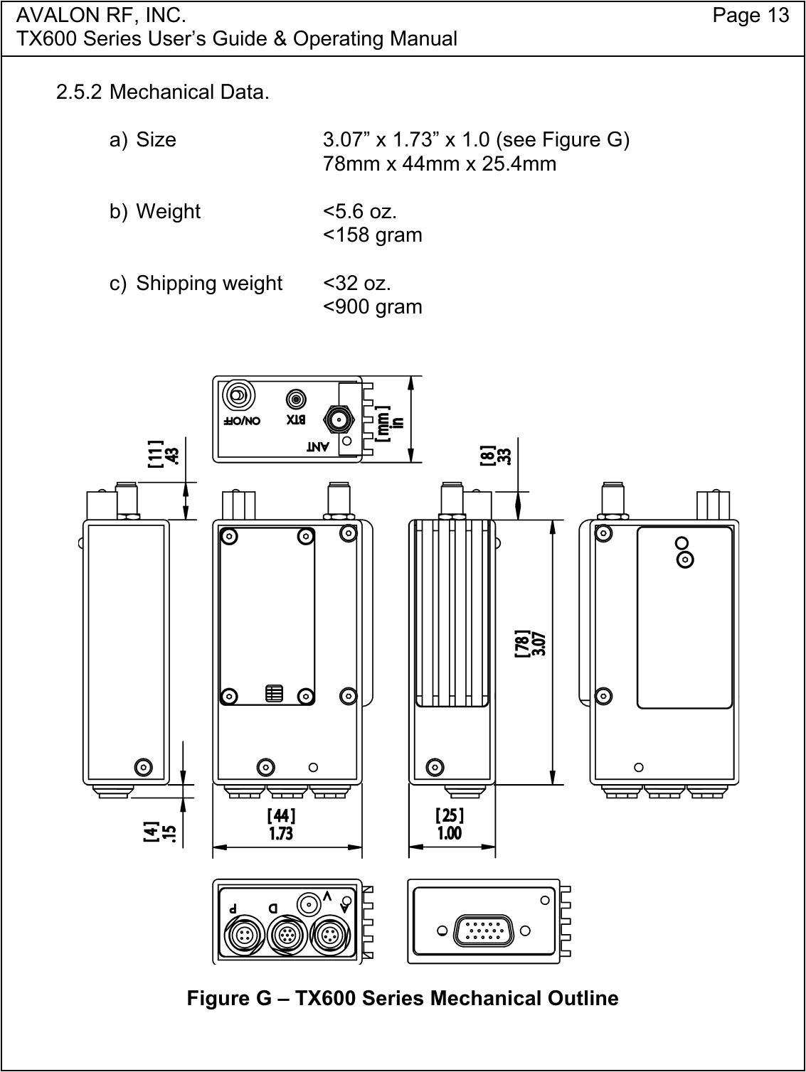
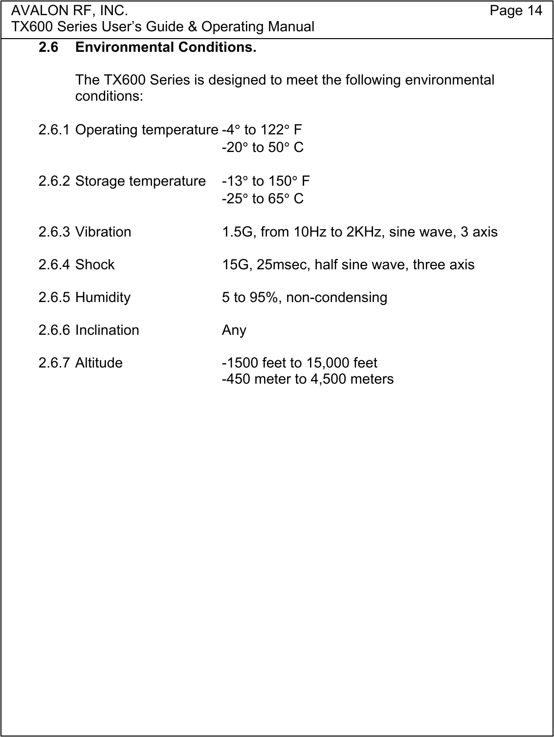
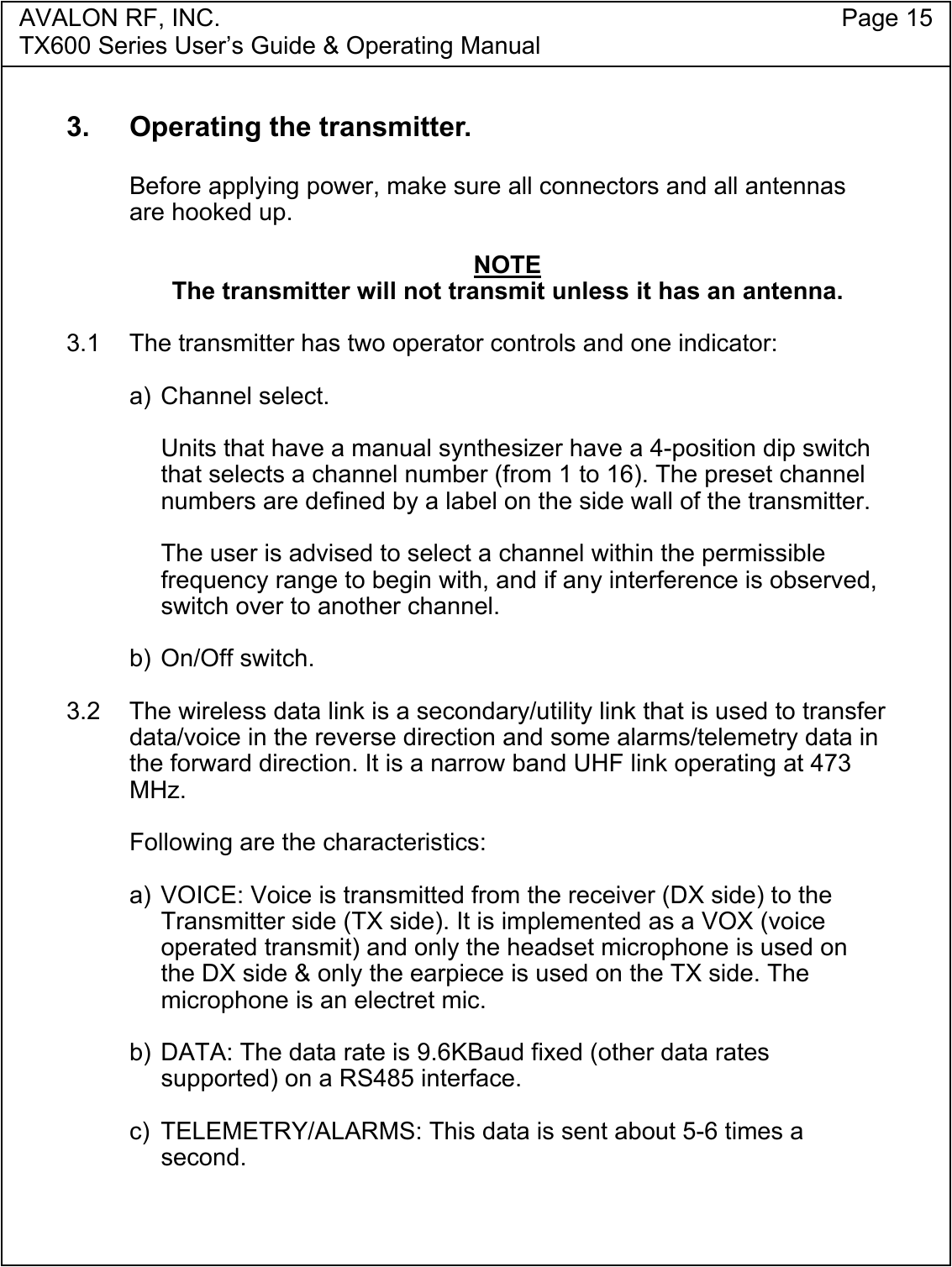
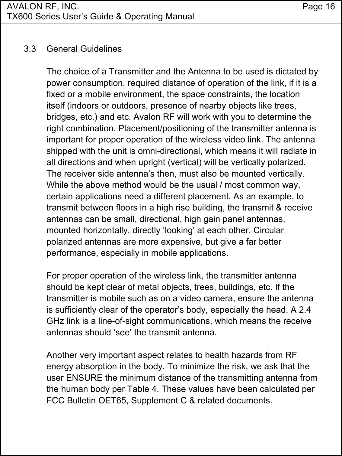
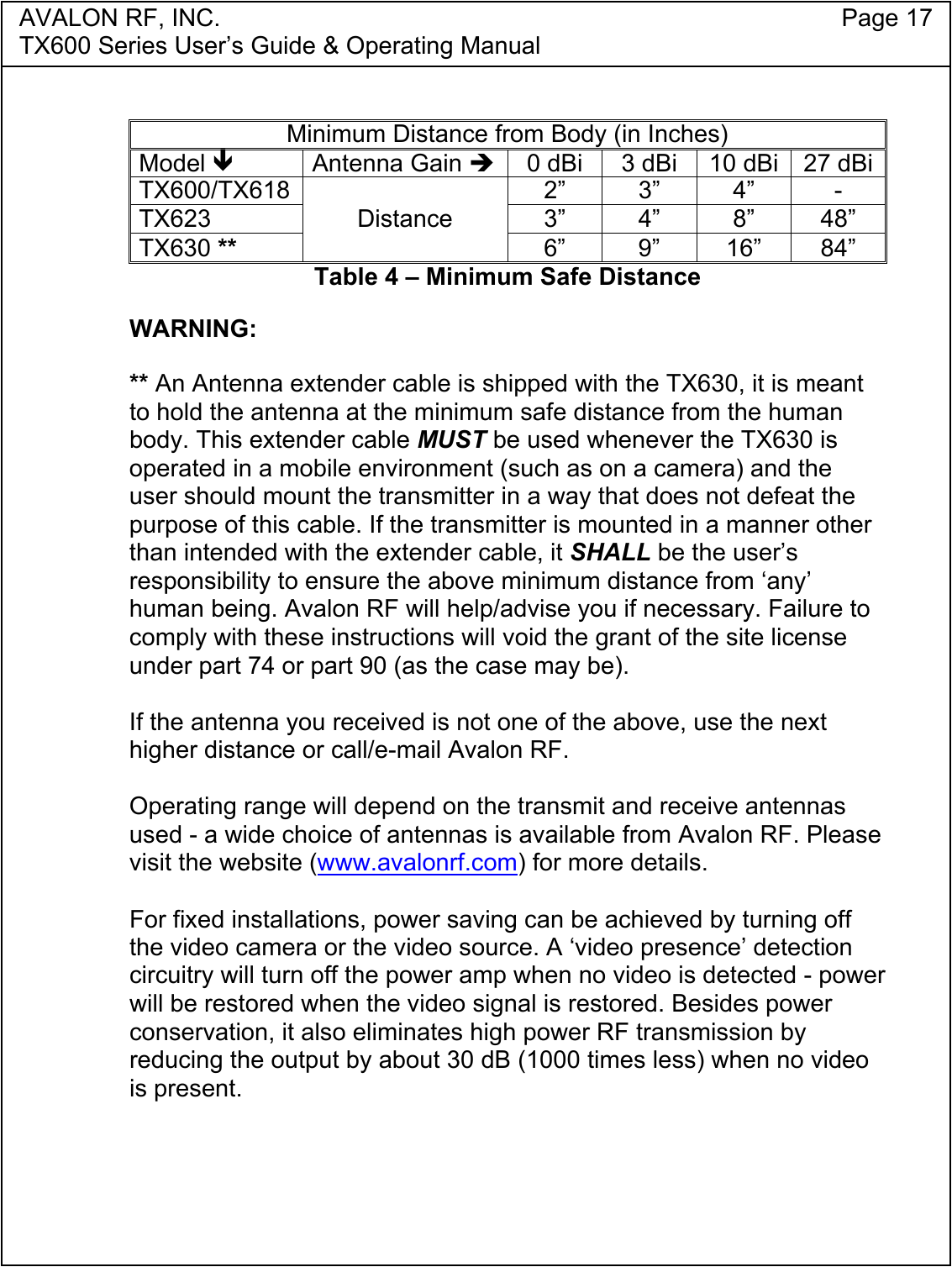
Avalon RF TX600-18-23-30 Wireless Video and Audio Transmitter User Manual TX600 Series Manual Rev C2

Avalon RF Inc. Wireless Video and Audio Transmitter TX600 Series Manual Rev C2

manual

Avalon RF, Inc. • 344 Coogan Way • El Cajon, CA 92020Phone: (619) 401-1969 • Fax: (619) 401-1971 • Email: sales@avalonrf.comTX600/TX618/TX623/TX6302.4GHz Video Transmitters User's Guide & Operating ManualAV030201/1-000REV. C2 - 1 October 2003FCC ID: Q7ITX600-18-23-30Authored by Guru MujumdarPrepared by Steve Joneshttp://www.avalonrf.com/
AVALON RF, INC. Page iiTX600 Series User’s Guide & Operating ManualFCC INFORMATIONFCC ID: Q7ITX600-18-23-30This unit complies with Parts 74 & 90 of the FCC regulations.Maximum Permissible ExposureAny Wireless Equipment can pose health hazards if precaution is notexercised in its use/operation, especially its proximity to the human body.Excessive absorption of RF energy in the body is known to cause Cancerand/or other diseases. The FCC has issued guidelines to determine thesafe distance of a transmitting antenna from the human body, to limitabsorption to safe levels. Please follow the instructions given in thismanual.WARNING: Refer to Table 4 in Section 3 (Operating the transmitter) todetermine the MINIMUM DISTANCE the Transmitter with Antennamounted, or the Antenna itself (if connected via coax to the transmitter),must be placed away from the body to minimize the health hazard.  Also,note the Warning for TX630 after Table 4. User’s failure to comply with theinstructions in this manual voids the site license granted.
AVALON RF, INC. Page iiiTX600 Series User’s Guide & Operating ManualTable of Contents1. General .................................................................................................1Table 1 – Model/Output Power .............................................................1Figure A – TX600 Series Controls and Connectors ..............................3Video.....................................................................................................4Audio.....................................................................................................4Talk Back Audio Channel (Optional).....................................................4Two Way Digital Data Link (DDL) (Optional) ........................................4Motion Sensor Input (Optional) .............................................................4Telemetry Input (Optional) ....................................................................5RF Outputs............................................................................................52. Specifications ........................................................................................6User Interface .......................................................................................6Setup ....................................................................................................6Electrical Interface ................................................................................7Table 2 – Current Consumption............................................................7Table 3 – Power Output ........................................................................8Interconnecting .....................................................................................9Figure B – DB 15 ..................................................................................9Figure C – Power/Video......................................................................10Figure D – Video.................................................................................10Figure E – Audio .................................................................................10Figure F – Data Input..........................................................................11Mounting .............................................................................................12Mechanical Data .................................................................................13Environmental Conditions ...................................................................143. Operating the transmitter. ...................................................................15Operater Controls & Indicators ...........................................................15General Guidelines .............................................................................16Table 4 – Minimum Safe Distance ......................................................174. Ordering information ...........................................................................18Base Models .......................................................................................18Options ...............................................................................................19Recommended Accessories ...............................................................20Antennas .........................................................................................20Table 5 – Permissible Antenna/Transmitter Model Combinations...21Cables .............................................................................................22Battery Packs ..................................................................................22
AVALON RF, INC. Page 1TX600 Series User’s Guide & Operating Manual1. GeneralThe TX600 series rugged transmitters are intended for use in military,homeland security, mobile security, broadcasting and motion pictureproduction.The TX600 Series is an FM modulated transmitter with a tuning rangeof 2.4GHz-2.483GHz and an optional extended range of 2.15GHz-2.5GHz.The following table details the RF output power of the various models:Model Output PowerTX600 1mWTX618 70mWTX623 200mWTX630 900mWTable 1 – Model/Output PowerEach Transmitter is available with a choice of 2 types of EndConnector’s:Suffix ‘B’ is Broadcast style and comes with LEMO connectors.Suffix ‘S’ is Security style and has only a DB15 connector.Refer to Figure ‘A’ for connector style.The type of connector is primarily a matter of preference for the user,with only 1 audio being a limitation of the ‘Security’ type. TheBroadcast industry also prefers to use the LEMO connector for itsrobustness for connect-disconnect applications, typical to thatindustry. LEMO connectors are also expensive connectors.While ordering, please specify the desired style with the above suffixe.g. TX630B for LEMO connectors.All transmitters offer the following features:•  A single broadcast quality video channel with no delay.•  One/Two broadcast quality audio channels depending on model.
AVALON RF, INC. Page 2TX600 Series User’s Guide & Operating ManualOptional features (each ordered individually).•  Two-way Wireless Data Link (WDL) to a DX series receiver.•  Talk back audio channel.•  Alarm/Motion sensor interface.• Telemetry inputs.
AVALON RF, INC. Page 3TX600 Series User’s Guide & Operating ManualTop View1 Power Switch2 WDL Antenna3 Main AntennaBottom View – Broadcast4 Power/Video Input – see Figure C5 Data Input – see Figures F6 Video Input – see Figure D7 Audio Input – see Figure EBottom View – Security8 Power/Video Input – see Figure BSide Views9 Power LED Indicator10 Channel Select Dip SwitchFigure A – TX600 Series Controls and Connectors
AVALON RF, INC. Page 4TX600 Series User’s Guide & Operating Manual1.1 Video.The video input is buffered, combined with the two audio subcarriers,then DC level restored, limited by a white level clipping circuit, pre-emphasized and FM modulates the transmitter RF carrier.Avalon RF offers the following video indices of modulation:•  Industry standard frequency deviation of 4MHz.Compatible to GMS, Coherent and others.This option offers longer range at reference quality.•  Wide frequency deviation of 6MHz.Compatible to Dynapix, Trango and others.This option offers broadcast quality but with slightly shorter range.1.2 Audio.The two audio inputs are buffered and FM modulated on twosubcarriers. The factory preset subcarrier frequency is 6MHz and6.5MHz but may be programmed to any frequency from 5MHz to7.5MHz.1.3  Talk Back Audio Channel (optional).The talk back audio channel allows the camera operator (on thetransmit side) to receive instructions from the operator at thereceiver’s side. It drives an earpiece.1.4  Two Way Wireless Digital Link (WDL) (optional).The WDL serves as a Pan-Tilt-Zoom (PTZ) / general-purpose two-way RS422/RS485 digital link.1.5  Alarm/Motion Sensor Input (optional).The motion sensor option turns the transmitter on whenever a drycontact relay closes an external circuit and controls a remote relay inthe receiver.
AVALON RF, INC. Page 5TX600 Series User’s Guide & Operating Manual1.6  Telemetry Inputs (optional).The telemetry input has 3 analog inputs. These inputs are sampledand transmitted out to the receiver through the WDL.1.7 RF Outputs.The transmitters have two RF outputs (Only 1 for a standard unit,without WDL or Talk Back Audio Option). A female SMA connectorfor the main transmitter and a MCX for the WDL.Both outputs feed antennas, either directly or through a cable.
AVALON RF, INC. Page 6TX600 Series User’s Guide & Operating Manual2. Specifications2.1 User Interface.a) On/Off Switch.The TX600 series transmitter has an on/off switch. This shuts offpower to the entire transmitter.b) Power on LED.This LED has the following states:i)  Green when power in on.ii) Red when the transmitter is on air.c) Hands Free Back Channel (optional).This option allows the receiver operator to communicate with thetransmitter operator via a headset that includes an earpiece and amicrophone, when the transmitter is on air.2.2 Setup.   The TX600 series transmitters have the following setups:a) Video carrier frequency (2.4GHz to 2.483GHz(*)).b) Audio 1 sub-carrier frequency (5MHz to 6MHz).c)  Audio 2 sub-carrier frequency (6MHz to 7.5MHz).(*) Option 04 extends the tuning range. See Section 4.
AVALON RF, INC. Page 7TX600 Series User’s Guide & Operating Manual2.3 Electrical Interface.The transmitter has the following interfaces:2.3.1 Power Inputa) The transmitters operate off a 9Vdc-16Vdc unregulated voltagesource.a)  This input is switched and protected against reverse polarity.b) Typical power input current consumption for the basicconfiguration is (with video present):Model Input CurrentTX600/TX618 <200mATX623 350mATX630 450mATable 2 – Current Consumption‘Video Presence’ detection circuitry will turn off the power amplifierif no video is detected. This conserves power considerably andreduces the RF output by more than 30 dB (1000 times less), if novideo is present.Addition of option 11 (WDL) will increase the current draw by amaximum of 170mA.2.3.2 Video Input.a) The video input accepts RS170, CCIR, NTSC or PAL signals.b) Input voltage is 1Vp.p with a negative sync tip of 0.3V.c)  The input impedance is 75 Ω (ohm).2.3.3 Audio 1 and Audio 2 Inputs.The audio inputs accept signals of 1Vp.p. and have an inputimpedance of 600 Ω (ohm).2.3.4 "Talk back" audio channel to the transmitter operator (optional).The “talk back” output drives an electromagnetic earpiece.
AVALON RF, INC. Page 8TX600 Series User’s Guide & Operating Manual2.3.5  Two Way Wireless Digital Link (WDL) (Option 11)The WDL is a 9.6KBaud (standard, other Baud rates are supported)Half-Duplex RS485 compatible serial interface.2.3.6  Main RF output to antenna.a) The main RF output connector is a 50 Ω (ohm) female SMAreceptacle.b) The RF output power is as follows:Model Output PowerTX600 1mW at VSWR of 1.5:1TX618 70mW at VSWR of 1.5:1TX623 200mW at VSWR of 1.5:1TX630 900mW at VSWR of 1.5:1Table 3 – Power Output2.3.8 Wireless Digital Link (WDL) RF output.The WDL RF output is via a 50 Ω (ohm) MCX connector. Maximumoutput power is 10dbm.The main RF and the WDL RF outputs are identical on all thetransmitter versions.2.3.9 Alarm/Motion Sensor input (optional – Security Type Only).The Alarm/Motion Sensor input is an interface to a dry contact relay.Whenever the relay circuit is closed, the transmitter goes on air.2.3.10 Telemetry inputs (optional).These analog inputs (3 on Security Type, 1 on Broadcast Type)have a 1M Ω (ohm) input impedance and a sampling rate of 500Hz.Resolution is 8 bit.
AVALON RF, INC. Page 9TX600 Series User’s Guide & Operating Manual2.4 Interconnecting.All interfaces to/from the transmitter are available in one of thefollowing connector configurations:2.4.1 Security Type - DB15P connector with the following pin-out:Figure B – DB15Pin # Function Pin # Function1 Power Input (+9Vdc to +16Vdc) 9 Signal Ground2 Video Input 10 Telemetry 1 Input3 Video Return Ground 11 Alarm/Motion Sensor Input4 Audio 1 Input 12 RS-485 I/O ‘A’5 Microphone Input 13 RS-485 I/O ‘B’6 Microphone Bias 14 Telemetry 2 Input7 Earpiece Output 15 Telemetry 3 Input8 Power Return GroundNOTE: This connector option allows for one audio input only, Audio 1 at 6.0MHz (default factory set).
AVALON RF, INC. Page 10TX600 Series User’s Guide & Operating Manual2.4.2 Broadcast Type - multiple connectors.a) Power/Video Input.PinNumber Function1 Power Return2 Video Input3 Video Return4 Power InputFigure C – Power/Videob) Video Input.The video signal is input either through the video 75 Ω (ohm) SMBconnector (Figure D) or the power connector (Figure C).Figure D – Videoc) Audio Input.PinNumber Function1 Audio Return2 Audio 1 Input3 Audio 2 Input4N/C5N/CFigure E – Audio
AVALON RF, INC. Page 11TX600 Series User’s Guide & Operating Manual2.4.2 Broadcast Type - multiple connectors (continued).c) Data Input.PinNumber Function1 Telemetry2 Microphone Input3 Speaker Output4 Microphone Bias Output5 RS-485 I/O ‘A’6 RS-485 I/O ‘B’7 GroundFigure F – Data Input
AVALON RF, INC. Page 12TX600 Series User’s Guide & Operating Manual2.5 Mechanical2.5.1 Mounting.Mounting can be done in one of the following methods:a) Clamping.Clamping (or hard mounting) is the only method of mounting in allfixed installations.Clamping is the preferred method of mounting in all mobileinstallations where most electrical interfaces are used. This is dueto the heat sinking needed and the weight of the connector’s andthe cable’s.b) Clip on.Avalon RF offers a clip on kit. This method is recommended whenonly one or two interfaces are in use. Not practical for TX623 andTX630.c) Velcro® to a flat surface.Using Velcro® to secure the transmitter is recommended whenonly a few interfaces are in use. Not practical for TX623 andTX630.d) Drop-in.The transmitter can be dropped into a bucket mounted on the sideof the video camera, like the ones usually found in ENG service.This can be done for the TX623 or TX630 only if adequateventilation (for cooling) is available in the bucket and care is takenwith other cables/equipment not being damaged from thetransmitter heat.
AVALON RF, INC. Page 13TX600 Series User’s Guide & Operating Manual2.5.2 Mechanical Data.a) Size 3.07” x 1.73” x 1.0 (see Figure G)78mm x 44mm x 25.4mmb) Weight <5.6 oz.<158 gramc) Shipping weight <32 oz.<900 gramFigure G – TX600 Series Mechanical Outline
AVALON RF, INC. Page 14TX600 Series User’s Guide & Operating Manual2.6 Environmental Conditions.The TX600 Series is designed to meet the following environmentalconditions:2.6.1 Operating temperature -4° to 122° F-20° to 50° C2.6.2 Storage temperature -13° to 150° F-25° to 65° C2.6.3 Vibration 1.5G, from 10Hz to 2KHz, sine wave, 3 axis2.6.4 Shock 15G, 25msec, half sine wave, three axis2.6.5 Humidity 5 to 95%, non-condensing2.6.6 Inclination Any2.6.7 Altitude -1500 feet to 15,000 feet-450 meter to 4,500 meters
AVALON RF, INC. Page 15TX600 Series User’s Guide & Operating Manual3.  Operating the transmitter.Before applying power, make sure all connectors and all antennasare hooked up.NOTEThe transmitter will not transmit unless it has an antenna.3.1  The transmitter has two operator controls and one indicator:a) Channel select.Units that have a manual synthesizer have a 4-position dip switchthat selects a channel number (from 1 to 16). The preset channelnumbers are defined by a label on the side wall of the transmitter.The user is advised to select a channel within the permissiblefrequency range to begin with, and if any interference is observed,switch over to another channel.b) On/Off switch.3.2  The wireless data link is a secondary/utility link that is used to transferdata/voice in the reverse direction and some alarms/telemetry data inthe forward direction. It is a narrow band UHF link operating at 473MHz.Following are the characteristics:a) VOICE: Voice is transmitted from the receiver (DX side) to theTransmitter side (TX side). It is implemented as a VOX (voiceoperated transmit) and only the headset microphone is used onthe DX side & only the earpiece is used on the TX side. Themicrophone is an electret mic.b) DATA: The data rate is 9.6KBaud fixed (other data ratessupported) on a RS485 interface.c) TELEMETRY/ALARMS: This data is sent about 5-6 times asecond.
AVALON RF, INC. Page 16TX600 Series User’s Guide & Operating Manual3.3 General GuidelinesThe choice of a Transmitter and the Antenna to be used is dictated bypower consumption, required distance of operation of the link, if it is afixed or a mobile environment, the space constraints, the locationitself (indoors or outdoors, presence of nearby objects like trees,bridges, etc.) and etc. Avalon RF will work with you to determine theright combination. Placement/positioning of the transmitter antenna isimportant for proper operation of the wireless video link. The antennashipped with the unit is omni-directional, which means it will radiate inall directions and when upright (vertical) will be vertically polarized.The receiver side antenna’s then, must also be mounted vertically.While the above method would be the usual / most common way,certain applications need a different placement. As an example, totransmit between floors in a high rise building, the transmit & receiveantennas can be small, directional, high gain panel antennas,mounted horizontally, directly ‘looking’ at each other. Circularpolarized antennas are more expensive, but give a far betterperformance, especially in mobile applications.For proper operation of the wireless link, the transmitter antennashould be kept clear of metal objects, trees, buildings, etc. If thetransmitter is mobile such as on a video camera, ensure the antennais sufficiently clear of the operator’s body, especially the head. A 2.4GHz link is a line-of-sight communications, which means the receiveantennas should ‘see’ the transmit antenna.Another very important aspect relates to health hazards from RFenergy absorption in the body. To minimize the risk, we ask that theuser ENSURE the minimum distance of the transmitting antenna fromthe human body per Table 4. These values have been calculated perFCC Bulletin OET65, Supplement C & related documents.
AVALON RF, INC. Page 17TX600 Series User’s Guide & Operating ManualMinimum Distance from Body (in Inches)Model !Antenna Gain "0 dBi 3 dBi 10 dBi 27 dBiTX600/TX618 2” 3” 4” -TX623 3” 4” 8” 48”TX630 **Distance6” 9” 16” 84”Table 4 – Minimum Safe DistanceWARNING:** An Antenna extender cable is shipped with the TX630, it is meantto hold the antenna at the minimum safe distance from the humanbody. This extender cable MUST be used whenever the TX630 isoperated in a mobile environment (such as on a camera) and theuser should mount the transmitter in a way that does not defeat thepurpose of this cable. If the transmitter is mounted in a manner otherthan intended with the extender cable, it SHALL be the user’sresponsibility to ensure the above minimum distance from ‘any’human being. Avalon RF will help/advise you if necessary. Failure tocomply with these instructions will void the grant of the site licenseunder part 74 or part 90 (as the case may be).If the antenna you received is not one of the above, use the nexthigher distance or call/e-mail Avalon RF.Operating range will depend on the transmit and receive antennasused - a wide choice of antennas is available from Avalon RF. Pleasevisit the website (www.avalonrf.com) for more details.For fixed installations, power saving can be achieved by turning offthe video camera or the video source. A ‘video presence’ detectioncircuitry will turn off the power amp when no video is detected - powerwill be restored when the video signal is restored. Besides powerconservation, it also eliminates high power RF transmission byreducing the output by about 30 dB (1000 times less) when no videois present.
AVALON RF, INC. Page 18TX600 Series User’s Guide & Operating Manual4. Ordering information4.1 Base ModelsTX600 2.4GHz-2.483GHz, FM modulated, O/P of 1mWTX618 2.4GHz-2.483GHz, FM modulated, O/P of 70mWTX623 2.4GHz-2.483GHz, FM modulated, O/P of 200mWTX630 2.4GHz-2.483GHz, FM modulated, O/P of 900mWNOTEModels with 200mW and up are licensed to customers per FCCPart 74 and Part 90 or for export only.While ordering, please specify the desired connector style with theproper suffix e.g. TX630B for LEMO connectors.Suffix ‘B’ is Broadcast style and comes with LEMO connectors.Suffix ‘S’ is Security style and has only a DB15 connector.Refer to Figure ‘A’ for connector style.All units come with the following standard accessories:4.1.1 Omni directional whip antenna4.1.2 A 3-foot power cord with flying leads, to be connected to a customerspecific battery pack.4.1.3 User guide and operating manual (this manual).4.1.4 A heavy-duty reusable carton.
AVALON RF, INC. Page 19TX600 Series User’s Guide & Operating Manual4.2 Options.4.2.1 Option 01 – Remote programming. Requires option 114.2.2  Option 04 – Extended tuning rangeTX600 series – 2.150GHz to 2.5GHzThis is ONLY the available range. User should indicate specificfrequencies licensed to them in this band at the time of ordering.4.2.3 Option 11 – Wireless Data Link (WDL)Includes an AX402 omni-directional whip antenna with MCXconnector.4.2.4 Option 31 – Talk back audio channel. Requires option 11.4.2.5 Option 41 – Alarm/Motion Sensor input. Requires option 11.4.2.6 Option 51 – Telemetry inputs (3 on Security Type, 1 on BroadcastType). Requires option 11.4.2.7 Option NM – Basic unit installed in an outdoor NEMA 4 box with aninternal power and signal distribution panel.4.2.8 Option SP – Basic unit installed in an outdoor NEMA 4 box withsolar panel, charger and internal lead-acid battery
AVALON RF, INC. Page 20TX600 Series User’s Guide & Operating Manual4.3 Recommended accessories.4.3.1 AntennasThe following is a list of antennas available from Avalon RF. Onlycertain antennas can be used with high power models like TX623 &TX630 to comply with FCC’s EIRP restrictions. Overseas customersmust check local regulations for compliance before ordering. Thechoice of a particular antenna is dictated by transmitter powerconsumption, the application environment, physical size constraints,governing local regulations, etc. As a rule, the higher the antennagain, the larger it’s size and narrower the beam width (the moredirectional the antenna).Omni-directional antennas for mobile application:Gain 2.4GHz Comments0dbi AX600 ¼ wave whip (needs ground plane)3dbi AX603CP Circular polarized whip3dbi AX603 Linear polarized4dbi AX604 Linear polarized6dbi AX606 Linear polarized8dbi AX608 Linear polarized10dbi AX610 Linear polarizedDirectional antennas for fixed point-to-point applications:Gain 2.4GHz Comments10dbi AX610CP Circular polarized panel13dbi AX613CP Circular polarized panel16dbi AX616CP Circular polarized panel24dbi AX624PD Parabolic Dish27dbi AX627PD Parabolic Dish
AVALON RF, INC. Page 21TX600 Series User’s Guide & Operating ManualThe following table shows permissible Antennas that can be used with thedifferent transmitters:Permissible for use with ModelAntenna FCC Part 15(License Free)RSS210(Canada)FCC Part 90(Licensed)FCC Part 74(Licensed)AX600 TX600 Any TX6XX Any TX6XX Any TX6XXAX603AX603CP -TX600TX618TX623Any TX6XX Any TX6XXAX604 -TX600TX618TX623Any TX6XX Any TX6XXAX606 -TX600TX618TX623Any TX6XX Any TX6XXAX608 - TX600TX618TX600TX618TX623Any TX6XXAX610AX610CP -TX600TX618TX600TX618TX623Any TX6XXAX613CP - TX600TX600TX618TX623TX600TX618TX623AX616CP - TX600 TX600TX618TX600TX618TX623AX624PD*AX627PD*- TX600 TX600 TX600* These antennas must be mounted on a roof or mast.Table 5 - Permissible Antenna/Transmitter Model Combinations
AVALON RF, INC. Page 22TX600 Series User’s Guide & Operating Manual4.3.2 CablesThe length of the cable between the transmitter and the antenna willhave a bearing on the output power transmitted. It is notrecommended to have more than 30 feet of cable, as the cable losswill become appreciable, even with a low loss cable. If a cable mustbe used, we recommend a low loss cable like the LMR240 orLMR400 or equivalent.4.3.3 Battery packsa) BAT80 – 14.4V/80WH Li-Ion battery pack with charger and powercable to transmitter - will run a TX630 transmitter for approximately9 hours.b) BAT92 – 14.4V/92WH Li-Ion battery pack with charger and powercable to transmitter - will run a TX630 transmitter for approximately12 hours.c)  BAT103 – 14.4V/103WH Li-Ion battery pack with charger andpower cable to transmitter - will run a TX630 transmitter forapproximately 15 hours.

Navigation menu