B plus B SmartWorx QTM85242000 Radio RF Modem, QTM-8524 User Manual man
B&B; Electronics Radio RF Modem, QTM-8524 man
UserManual.wiki
>
B plus B SmartWorx
>
QTM85242000 User Manual
>
manual
Contents
1.
manual
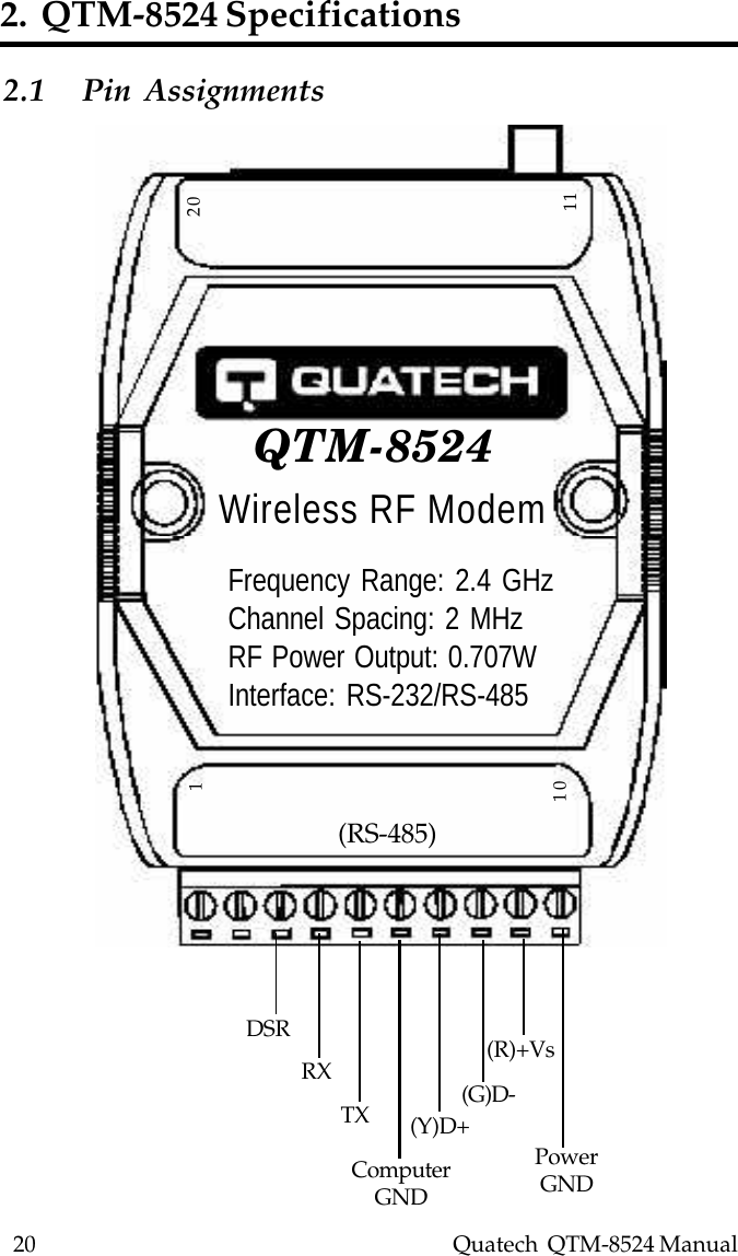
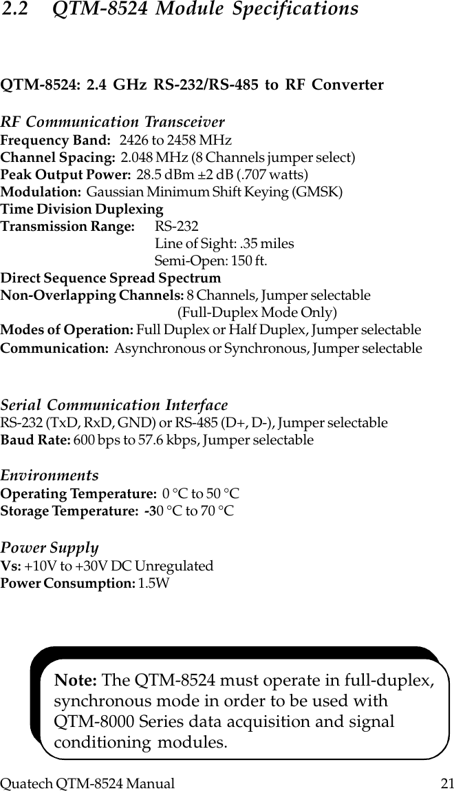
2.
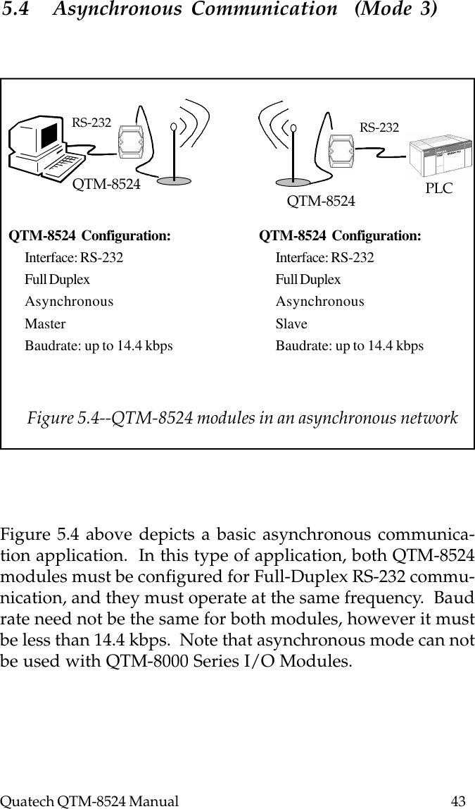
page 34 has revised warning statement in manual
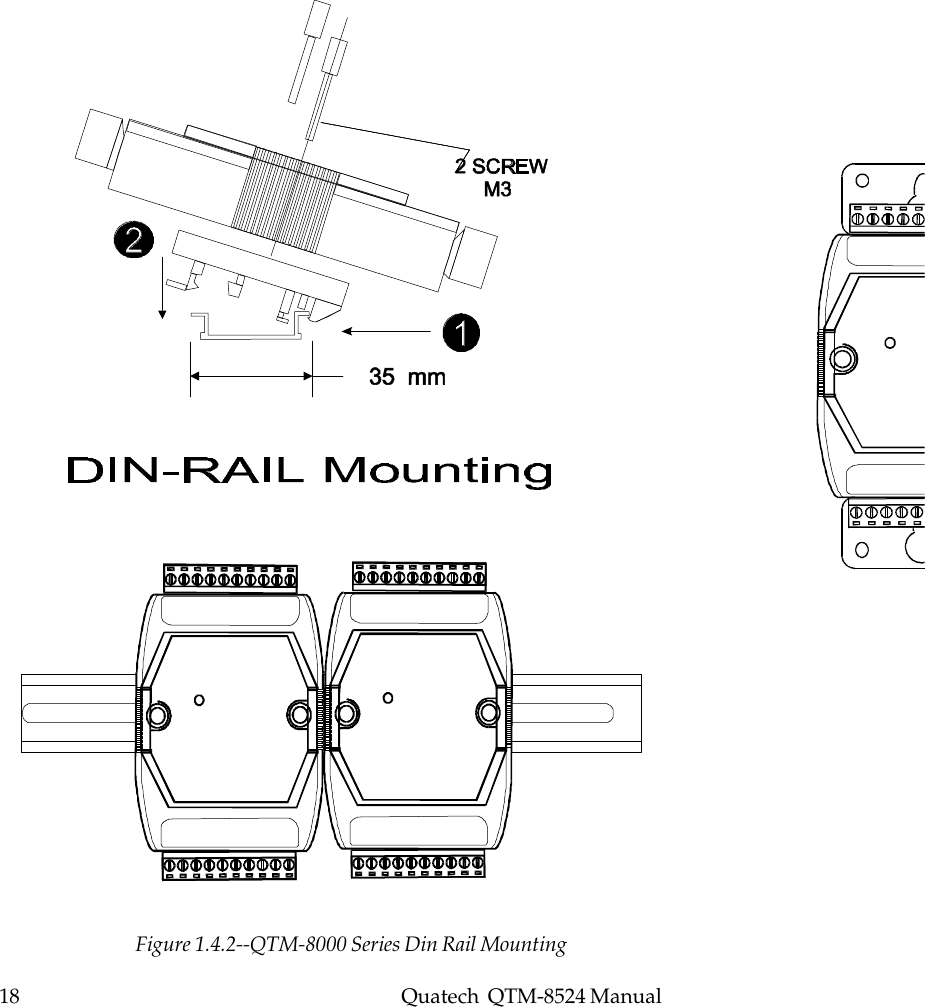
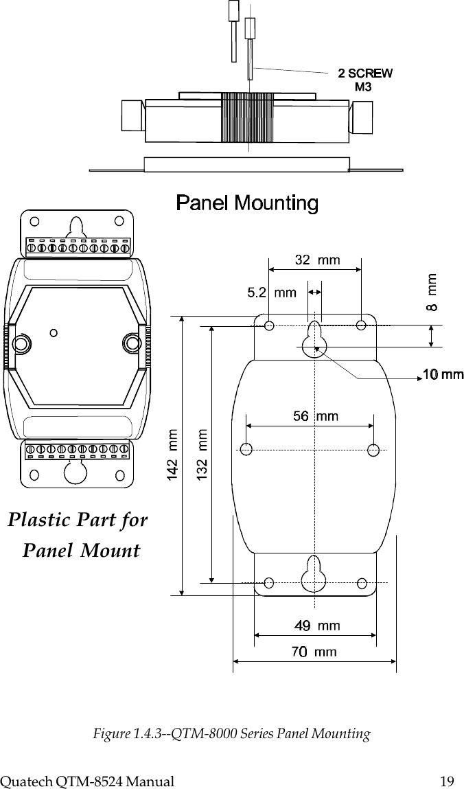
manual
Navigation menu
Upload a User Manual
Namespaces
Wiki Guide
HTML
PDF
Info
Views
User Manual
Discussion / Help
Navigation