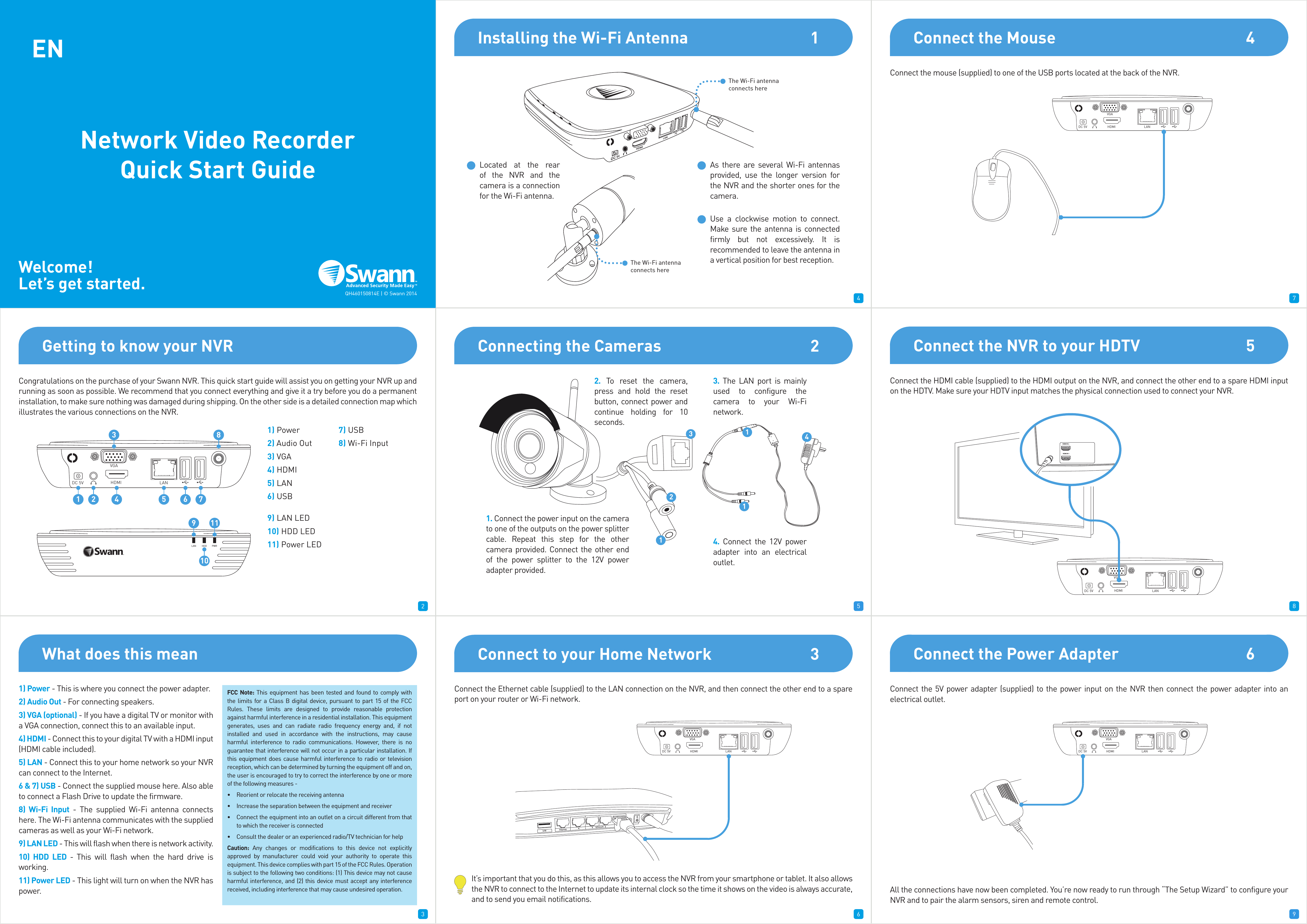
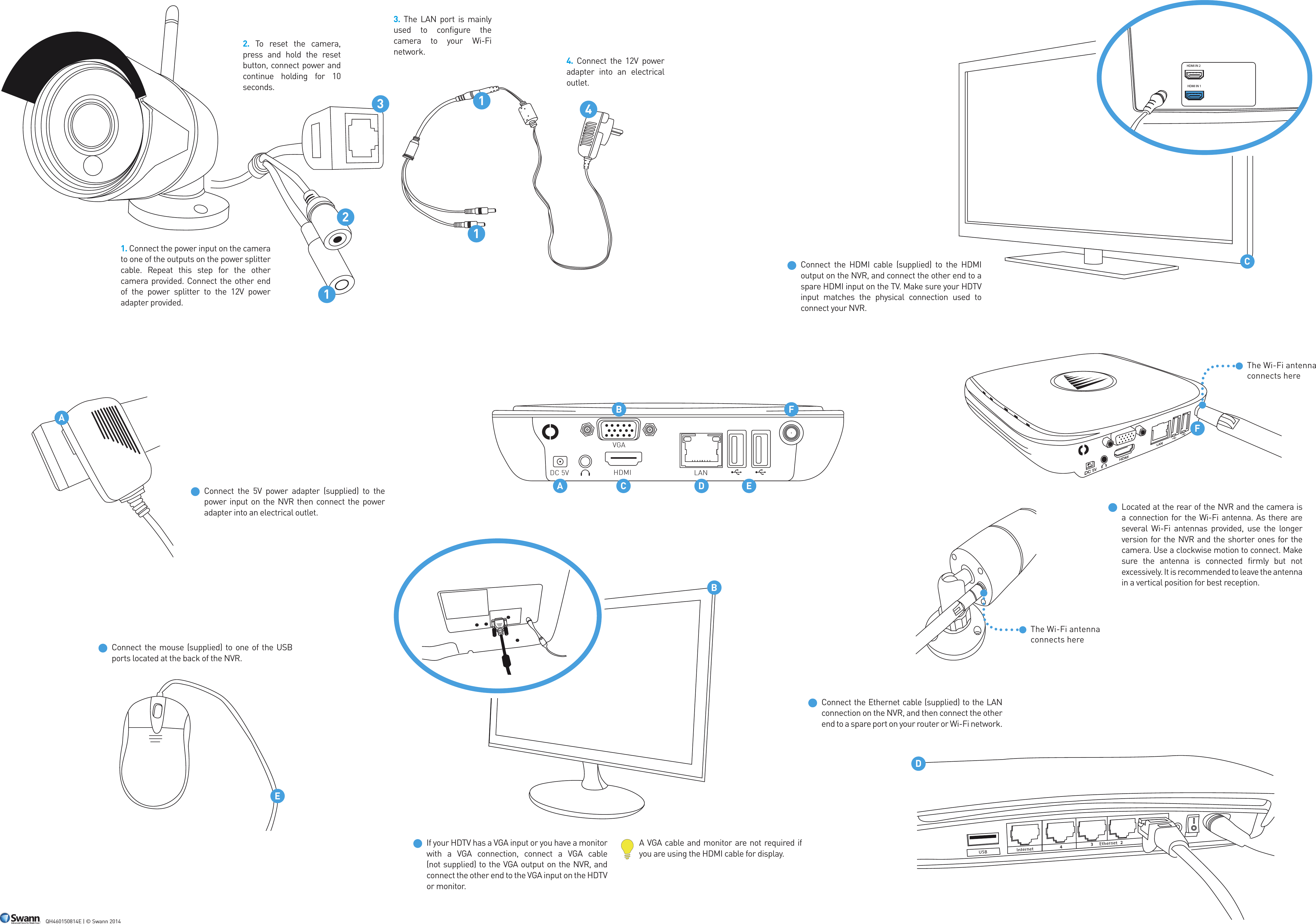
BAICHUAN SECURITY TECHNOLOGY 460CAM WIFI IP Camera User Manual

SHENZHEN BAICHUAN SECURITY TECHNOLOGY CO., LTD WIFI IP Camera Users Manual

Users Manual

1 2 34 5 67 8 91Congratulations on the purchase of your Swann NVR. This quick start guide will assist you on getting your NVR up and running as soon as possible. We recommend that you connect everything and give it a try before you do a permanent installation, to make sure nothing was damaged during shipping. On the other side is a detailed connection map which illustrates the various connections on the NVR.1) Power2) Audio Out3) VGA4) HDMI5) LAN6) USB7) USB8) Wi-Fi Input9) LAN LED10) HDD LED11) Power LEDConnect the Ethernet cable (supplied) to the LAN connection on the NVR, and then connect the other end to a spare port on your router or Wi-Fi network.It’s important that you do this, as this allows you to access the NVR from your smartphone or tablet. It also allows the NVR to connect to the Internet to update its internal clock so the time it shows on the video is always accurate, and to send you email notifications.Connect the mouse (supplied) to one of the USB ports located at the back of the NVR.Connect the 5V power adapter (supplied) to the power input on the NVR then connect the power adapter into an electrical outlet.All the connections have now been completed. You’re now ready to run through “The Setup Wizard” to configure your NVR and to pair the alarm sensors, siren and remote control.Connect the HDMI cable (supplied) to the HDMI output on the NVR, and connect the other end to a spare HDMI input on the HDTV. Make sure your HDTV input matches the physical connection used to connect your NVR.234678Getting to know your NVRDC 5V HDMIVGALAN1 2 435 6 78LAN HDD PWR9 1110Installing the Wi-Fi Antenna 1Connecting the Cameras 2Use a clockwise motion to connect. Make sure the antenna is connected firmly but not excessively. It is recommended to leave the antenna in a vertical position for best reception.Located at the rear of the NVR and the camera is a connection for the Wi-Fi antenna. As there are several Wi-Fi antennas provided, use the longer version for the NVR and the shorter ones for the camera.The Wi-Fi antenna connects hereThe Wi-Fi antenna connects here1. Connect the power input on the camera to one of the outputs on the power splitter cable. Repeat this step for the other camera provided. Connect the other end of the power splitter to the 12V power adapter provided.2. To reset the camera, press and hold the reset button, connect power and continue holding for 10 seconds. 3. The LAN port is mainly used to configure the camera to your Wi-Fi network. 4. Connect the 12V power adapter into an electrical outlet.Connect to your Home Network 3USB Inte rnet Ethernet432DC 5V HDMIVGALANConnect the Mouse 4DC 5V HDMIVGALANConnect the NVR to your HDTV 5DC 5V HDMIVGALANHDMI IN 2HDMI IN 1Connect the Power Adapter 6DC 5V HDMIVGALAN1123411ENNetwork Video Recorder Quick Start GuideWelcome!Let’s get started. QH460150814E | © Swann 2014What does this mean1) Power - This is where you connect the power adapter.2) Audio Out - For connecting speakers.3) VGA (optional) - If you have a digital TV or monitor with a VGA connection, connect this to an available input.4) HDMI - Connect this to your digital TV with a HDMI input (HDMI cable included).5) LAN - Connect this to your home network so your NVR can connect to the Internet.6 & 7) USB - Connect the supplied mouse here. Also able to connect a Flash Drive to update the firmware.8) Wi-Fi Input - The supplied Wi-Fi antenna connects here. The Wi-Fi antenna communicates with the supplied cameras as well as your Wi-Fi network.9) LAN LED - This will flash when there is network activity.10) HDD LED - This will flash when the hard drive is working.11) Power LED - This light will turn on when the NVR has power.FCC Note: This equipment has been tested and found to comply with the limits for a Class B digital device, pursuant to part 15 of the FCC Rules. These limits are designed to provide reasonable protection against harmful interference in a residential installation. This equipment generates, uses and can radiate radio frequency energy and, if not installed and used in accordance with the instructions, may cause harmful interference to radio communications. However, there is no guarantee that interference will not occur in a particular installation. If this equipment does cause harmful interference to radio or television reception, which can be determined by turning the equipment off and on, the user is encouraged to try to correct the interference by one or more of the following measures -•  Reorient or relocate the receiving antenna•  Increase the separation between the equipment and receiver•  Connect the equipment into an outlet on a circuit different from that to which the receiver is connected•  Consult the dealer or an experienced radio/TV technician for helpCaution: Any changes or modifications to this device not explicitly approved by manufacturer could void your authority to operate this equipment. This device complies with part 15 of the FCC Rules. Operation is subject to the following two conditions: (1) This device may not cause harmful interference, and (2) this device must accept any interference received, including interference that may cause undesired operation.
10 11 1213 14 1516 17 181. Connect the power input on the camera to one of the outputs on the power splitter cable. Repeat this step for the other camera provided. Connect the other end of the power splitter to the 12V power adapter provided.2. To reset the camera, press and hold the reset button, connect power and continue holding for 10 seconds. 3. The LAN port is mainly used to configure the camera to your Wi-Fi network. 4. Connect the 12V power adapter into an electrical outlet.Connect the HDMI cable (supplied) to the HDMI output on the NVR, and connect the other end to a spare HDMI input on the TV. Make sure your HDTV input matches the physical connection used to connect your NVR.Located at the rear of the NVR and the camera is a connection for the Wi-Fi antenna. As there are several Wi-Fi antennas provided, use the longer version for the NVR and the shorter ones for the camera. Use a clockwise motion to connect. Make sure the antenna is connected firmly but not excessively. It is recommended to leave the antenna in a vertical position for best reception.Connect the 5V power adapter (supplied) to the power input on the NVR then connect the power adapter into an electrical outlet.Connect the Ethernet cable (supplied) to the LAN connection on the NVR, and then connect the other end to a spare port on your router or Wi-Fi network.If your HDTV has a VGA input or you have a monitor with a VGA connection, connect a VGA cable (not supplied) to the VGA output on the NVR, and connect the other end to the VGA input on the HDTV or monitor.A VGA cable and monitor are not required if you are using the HDMI cable for display.Connect the mouse (supplied) to one of the USB ports located at the back of the NVR.QH460150814E | © Swann 2014HDMI IN 2HDMI IN 1CUSB Internet Ethernet432DBEDC 5V HDMIVGALAN112341The Wi-Fi antenna connects hereAACBDEFFThe Wi-Fi antenna connects here
FCC NOTE  This equipment has been tested and found to comply with the limits for a Class B digital device, pursuant to part 15 of the FCC Rules. These limits are designed to provide reasonable protection against harmful interference in a residential installation. This equipment generates, uses and can radiate radio frequency energy and, if not installed and used in accordance with the instructions, may cause harmful interference to radio communications. However, there is no guarantee that interference will not occur in a particular installation. If this equipment does cause harmful interference to radio or television reception, which can be determined by turning the equipment off and on, the user is encouraged to try to correct the interference by one or more of the following measures:  -- Reorient or relocate the receiving antenna. -- Increase the separation between the equipment and receiver. -- Connect the equipment into an outlet on a circuit different from that to which -- the receiver is connected. -- Consult the dealer or an experienced radio/TV technician for help.    These devices comply with part 15 of the FCC Rules. Operation is subject to the following two conditions: 1) These devices may not cause harmful interference, and 2) These devices must accept any interference received, including interference that may cause undesired operation  Caution: Any changes or modifications to this device not explicitly approved by manufacturer could void your authority to operate this equipment.  This equipment complies with FCC RF radiation exposure limits set forth for an uncontrolled environment. This device and its antenna must not be located or operating in conjunction with any other antenna or transmitter.  The transmitter must not be co-located or operated in conjunction with any other antenna or transmitter. This equipment complies with the FCC RF radiation exposure limits set forth for an uncontrolled environment. This equipment should be installed and operated with a minimum distance of 20cm between the radiator and any part of your body.

Navigation menu