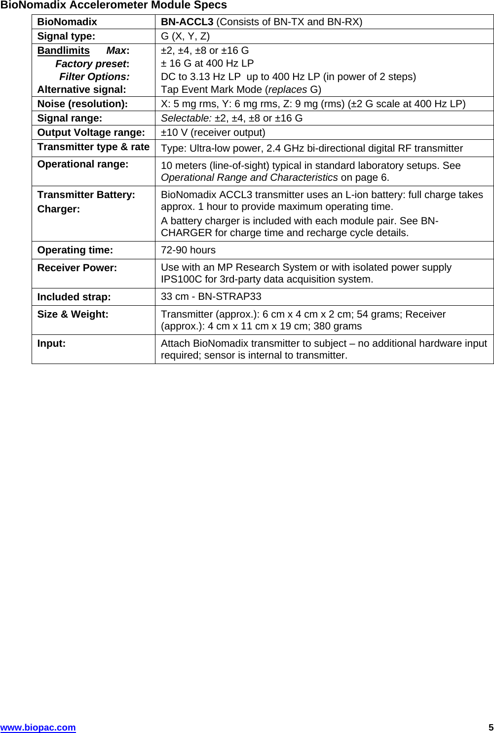
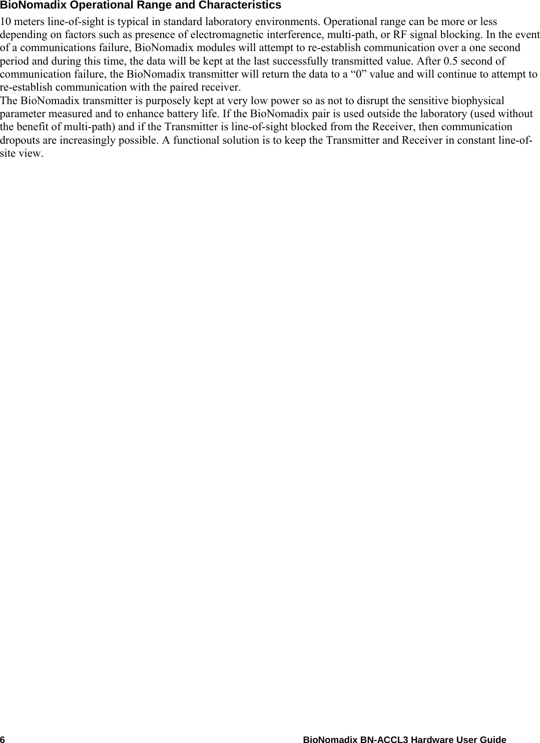
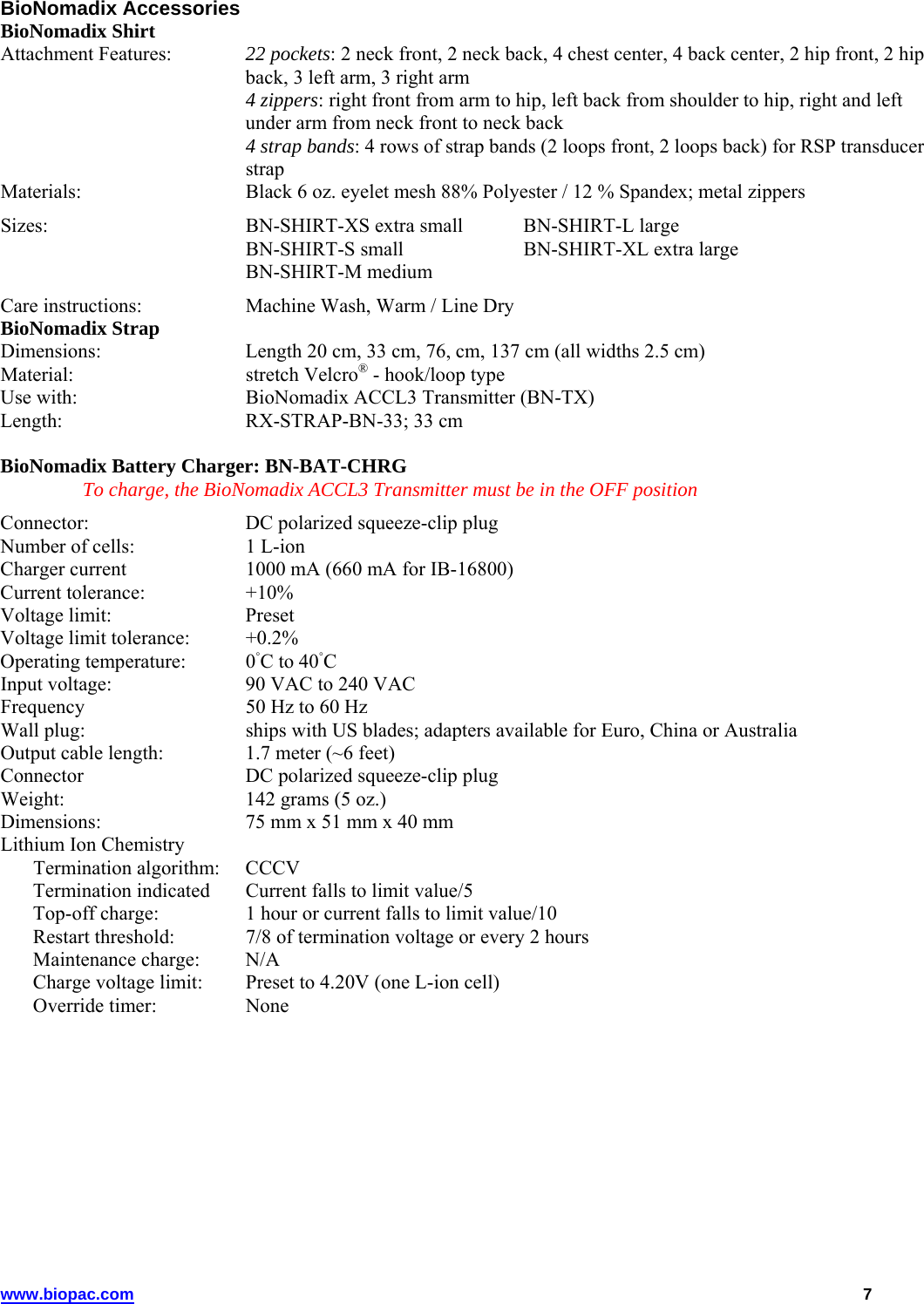
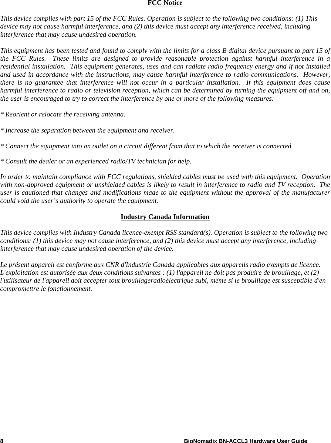
BIOPAC Systems BNXT1 BioNomadix Transmitter User Manual BioNomadix Hardware User Guide

BIOPAC Systems, Inc. BioNomadix Transmitter BioNomadix Hardware User Guide

Owners Manual

User Guide for BioNomadix Transmitter (BN-TX) and BioNomadix Receiver (BN-RX)     The BioNomadix Hardware Guide describes how to connect and set up the BioNomadix Accelerometer Transmitter/Receiver module for use with an MP150 System, Isolated Power Supply, (IPS100C) and details applications and uses for the MP System.   All specifications are subject to change without notice.                         Rev. 1.1  11.22.2011     This manual supersedes all previous manuals  BIOPAC Systems, Inc. 42 Aero Camino, Goleta, CA 93117 Tel (805) 685-0066 | Fax (805) 685-0067 www.biopac.com
 BIONOMADIX BN-ACCL3 MODULE BioNomadix Accelerometry X, Y, Z — Wireless Physiology The BioNomadix Tri-axial Accelerometer (BN-ACCL3) is a broad spectrum acceleration measurement system. The transmitter can be attached to any part of the subject's body to measure three-axis acceleration associated with movement in that particular location. The system comes factory preset to support an operational range of ±16 G, with a maximum system bandwidth of 400 Hz.  Ranges can be set to as low as ±2 G with bandwidths as low as 3 Hz. The system can also be configured to act as a "tap detector," detect either single or double taps. In this mode, the system can act as an event recorder for self-report. When "double-tapped," for example, the system will output a pulse to precisely mark the time location of the observed event. In Acceleration measurement mode, the BN-ACCL3 will output X, Y and Z acceleration values on three associated channels. The system is very well suited for mobile applications. The system can measure the acceleration of gravity (static) for tilt-sensing and can also measure very fast-changing, dynamic acceleration resulting from rapid movement or impact. The BioNomadix Accelerometer module is capable of recording three independent X, Y and Z channels.  2    BioNomadix BN-ACCL3 Hardware User Guide
Setup Overview 1. Setup the BioNomadix ACCL3 Transmitter (BN-TX) with subject. 2. Setup the BioNomadix ACCL3 Receiver (BN-RX). 3. Setup the software. Hardware Setup The BioNomadix ACCL3 Transmitter and Receiver unit are shipped as a matched pair and must always be used as a pair (see serial number and ID sync options). Up to 16 channels per BioNomadix system can be monitored simultaneously, returning data quality equal to standard BIOPAC MP modules. Normal operating range between transmitter and receiver is 10 meters line of sight in standard laboratory environments. BioNomadix Transmitter Setup 1. Secure the Transmitter module on Subject, (i.e. with a strap, or inside a BioNomadix shirt pocket).   For optimum results, the BioNomadix Custom Sport Shirt is recommended. This specially-designed shirt is made of a lightweight material with numerous “pockets” for housing multiple transmitters.  2. Set the power switch on the BioNomadix Transmitter to ON. The Status light will flash sequences based upon connectivity and battery life. Single blinks every half second indicates that the transmitter and receiver are not communicating. 3. Double blinks occurring every two seconds indicate successful pairing and normal operation between transmitter and receiver.  Controls ID: Press to illuminate Status light of matching Receiver unit.  On/Off: Power switch for the transmitter. The transmitter power must be turned OFF for charging. Status: Solid amber when battery power is low. Approximately one hour of operation remains after light turns amber, full-charge with BN-BAT-CGR battery charger typically requires one hour.  BioNomadix Receiver BEFORE BEGINNING:   Decide whether one or both available channels will be used. (If using only one channel, set “X” to ON and “Y” and “Z” to OFF)  Set channel slider to correct position.  Attach Receiver unit to the right side of the MP150 unit, or the left side of the IPS100C. The Status light will turn green when communicating with transmitter.  Set desired channel options on the Receiver module. www.biopac.com   3
 Accelerometer Receiver unit controls:  Wireless antenna input Receiver LED: Steady green when paired with transmitter. Blinks amber once per 4    BioNomadix BN-ACCL3 Hardware User Guide second when communication is interrupted. Input Signals: X, Y & Z   “X”   Assigns the input signals for channels 1-4.  “Y”  Assigns the input signals for channels 5-8 “Z”   Assigns the input signals for channels 9-12. On/Off  Enables or disables module channels: “X” channels 1-4, “Y” channels 5-8, Z channels 9-12.                Transmitter Battery Life Transmitter battery life is described below as a change of color in the sequence of LED flashes. LED Color Pattern  Charge % green green green green  75% - 100%   yellow green green green  50% - 75% yellow yellow green  green  25% - 50% yellow  yellow yellow green  5% - 25% yellow yellow yellow yellow < 5%  System Setup Connect the BioNomadix Receiver to the right side of the MP150, and then turn on the MP150 power button. Data acquisition to MP150 will proceed as programmed. Transmitter Characteristics If the paired signal is interrupted due to electrical interference or a subject wandering out of range, the most recently-acquired data point to the MP150 will be retained, with normal wireless transmission continuing once communication is reestablished. See BioNomadix Operational Range and Characteristics on page 6.
BioNomadix Accelerometer Module Specs  BioNomadix  BN-ACCL3 (Consists of BN-TX and BN-RX) Signal type:    G (X, Y, Z) Bandlimits Max:  Factory preset:  Filter Options: Alternative signal:  ±2, ±4, ±8 or ±16 G ± 16 G at 400 Hz LP DC to 3.13 Hz LP  up to 400 Hz LP (in power of 2 steps) Tap Event Mark Mode (replaces G) Noise (resolution): X: 5 mg rms, Y: 6 mg rms, Z: 9 mg (rms) (±2 G scale at 400 Hz LP) Signal range:  Selectable: ±2, ±4, ±8 or ±16 G Output Voltage range:  ±10 V (receiver output) Transmitter type & rate  Type: Ultra-low power, 2.4 GHz bi-directional digital RF transmitter Operational range:  10 meters (line-of-sight) typical in standard laboratory setups. See Operational Range and Characteristics on page 6. Transmitter Battery: Charger: BioNomadix ACCL3 transmitter uses an L-ion battery: full charge takes approx. 1 hour to provide maximum operating time. A battery charger is included with each module pair. See BN-CHARGER for charge time and recharge cycle details. Operating time:  72-90 hours Receiver Power:  Use with an MP Research System or with isolated power supply IPS100C for 3rd-party data acquisition system. Included strap:  33 cm - BN-STRAP33 Size & Weight:  Transmitter (approx.): 6 cm x 4 cm x 2 cm; 54 grams; Receiver (approx.): 4 cm x 11 cm x 19 cm; 380 grams Input:  Attach BioNomadix transmitter to subject – no additional hardware input required; sensor is internal to transmitter. www.biopac.com   5
6    BioNomadix BN-ACCL3 Hardware User Guide BioNomadix Operational Range and Characteristics 10 meters line-of-sight is typical in standard laboratory environments. Operational range can be more or less depending on factors such as presence of electromagnetic interference, multi-path, or RF signal blocking. In the event of a communications failure, BioNomadix modules will attempt to re-establish communication over a one second period and during this time, the data will be kept at the last successfully transmitted value. After 0.5 second of communication failure, the BioNomadix transmitter will return the data to a “0” value and will continue to attempt to re-establish communication with the paired receiver. The BioNomadix transmitter is purposely kept at very low power so as not to disrupt the sensitive biophysical parameter measured and to enhance battery life. If the BioNomadix pair is used outside the laboratory (used without the benefit of multi-path) and if the Transmitter is line-of-sight blocked from the Receiver, then communication dropouts are increasingly possible. A functional solution is to keep the Transmitter and Receiver in constant line-of-site view.
www.biopac.com   7 BioNomadix Accessories BioNomadix Shirt  Attachment Features:   22 pockets: 2 neck front, 2 neck back, 4 chest center, 4 back center, 2 hip front, 2 hip back, 3 left arm, 3 right arm   4 zippers: right front from arm to hip, left back from shoulder to hip, right and left under arm from neck front to neck back    4 strap bands: 4 rows of strap bands (2 loops front, 2 loops back) for RSP transducer strap Materials:   Black 6 oz. eyelet mesh 88% Polyester / 12 % Spandex; metal zippers Sizes:  BN-SHIRT-XS extra small  BN-SHIRT-L large   BN-SHIRT-S small    BN-SHIRT-XL extra large  BN-SHIRT-M medium Care instructions:   Machine Wash, Warm / Line Dry BioNomadix Strap  Dimensions:   Length 20 cm, 33 cm, 76, cm, 137 cm (all widths 2.5 cm) Material:   stretch Velcro® - hook/loop type Use with:   BioNomadix ACCL3 Transmitter (BN-TX) Length:  RX-STRAP-BN-33; 33 cm   BioNomadix Battery Charger: BN-BAT-CHRG  To charge, the BioNomadix ACCL3 Transmitter must be in the OFF position Connector:  DC polarized squeeze-clip plug Number of cells:  1 L-ion Charger current  1000 mA (660 mA for IB-16800) Current tolerance:   +10% Voltage limit:   Preset Voltage limit tolerance:  +0.2% Operating temperature:  0◦C to 40◦C Input voltage:  90 VAC to 240 VAC Frequency  50 Hz to 60 Hz Wall plug:  ships with US blades; adapters available for Euro, China or Australia Output cable length:  1.7 meter (~6 feet) Connector  DC polarized squeeze-clip plug Weight:   142 grams (5 oz.) Dimensions:   75 mm x 51 mm x 40 mm Lithium Ion Chemistry    Termination algorithm:  CCCV     Termination indicated  Current falls to limit value/5     Top-off charge:  1 hour or current falls to limit value/10     Restart threshold:  7/8 of termination voltage or every 2 hours   Maintenance charge:  N/A     Charge voltage limit:  Preset to 4.20V (one L-ion cell)   Override timer:  None
8    BioNomadix BN-ACCL3 Hardware User Guide  FCC Notice  This device complies with part 15 of the FCC Rules. Operation is subject to the following two conditions: (1) This device may not cause harmful interference, and (2) this device must accept any interference received, including interference that may cause undesired operation.  This equipment has been tested and found to comply with the limits for a class B digital device pursuant to part 15 of the FCC Rules.  These limits are designed to provide reasonable protection against harmful interference in a residential installation.  This equipment generates, uses and can radiate radio frequency energy and if not installed and used in accordance with the instructions, may cause harmful interference to radio communications.  However, there is no guarantee that interference will not occur in a particular installation.  If this equipment does cause harmful interference to radio or television reception, which can be determined by turning the equipment off and on, the user is encouraged to try to correct the interference by one or more of the following measures:  * Reorient or relocate the receiving antenna.  * Increase the separation between the equipment and receiver.  * Connect the equipment into an outlet on a circuit different from that to which the receiver is connected.  * Consult the dealer or an experienced radio/TV technician for help.  In order to maintain compliance with FCC regulations, shielded cables must be used with this equipment.  Operation with non-approved equipment or unshielded cables is likely to result in interference to radio and TV reception.  The user is cautioned that changes and modifications made to the equipment without the approval of the manufacturer could void the user’s authority to operate the equipment.  Industry Canada Information  This device complies with Industry Canada licence-exempt RSS standard(s). Operation is subject to the following two conditions: (1) this device may not cause interference, and (2) this device must accept any interference, including interference that may cause undesired operation of the device.  Le présent appareil est conforme aux CNR d'Industrie Canada applicables aux appareils radio exempts de licence. L'exploitation est autorisée aux deux conditions suivantes : (1) l'appareil ne doit pas produire de brouillage, et (2) l'utilisateur de l'appareil doit accepter tout brouillageradioélectrique subi, même si le brouillage est susceptible d'en compromettre le fonctionnement.
www.biopac.com   9 BioNomadix—Advanced Setup Options Isolated Power Supply To use BioNomadix with the Isolated Power Supply (IPS100C), connect the BioNomadix receiver to the left side and turn on the IPS100C power button. The power light, on the front panel of the IPS100C, signals that BioNomadix receiver is powered ON. Signal Validation BioNomadix units are factory-calibrated but if user-calibration is desired for measurement verification the following steps may be used:   Accelerometer  Orient Transmitter unit in the X, Y, and Z directions with respect to Earth’s gravity. Measurements should be approximately 1 g.
   Filter Option Switch Guide       Switches are on the back of the BioNomadix receiver. Adjust switch position with a small tipped screwdriver.   Switch positions: “UP” = ON, DOWN” = OFF NOTE: If the switch settings are modified, preset MP150 module setup cannot be used and channels must be configured manually.  ACCL3-R BioNomadix Receiver Filter Option  Switch Number Rate SW1 SW2 SW3 6.25 Hz  UP  UP  UP 12.5 Hz  DOWN  UP  UP 25 Hz  UP  DOWN  UP 50 Hz  DOWN  DOWN  UP 100 Hz  UP  UP  DOWN 200 Hz  DOWN  UP  DOWN 400 Hz  UP  DOWN  DOWN 800 Hz  DOWN* DOWN* DOWN*  Range  SW4  SW5 2 G  UP  UP 4 G  DOWN  UP 8 G  UP  DOWN G-Mode 16 G  DOWN* DOWN*  *Indicates Factory Preset10    BioNomadix BN-ACCL3 Hardware User Guide
   Alternative Signal Switch Guide       ACCL3-R BioNomadix Receiver G – Factory Preset  DOWN Tap (Event Mark) – Alternative Signal UP Signal Output  SW6 G-Mode  DOWN Tap Mode  UP  ACCL3-R switch settings for Alternative Signal TAP  Filter Option Switch Number Rate (G-Mode) or Duration (Tap Mode) SW1 SW2 SW3 5000 μS  UP  UP  UP 4375 μS  DOWN  UP  UP 3750 μS  UP  DOWN  UP 3125 μS  DOWN  DOWN  UP 2500 μS  UP  UP  DOWN 1875 μS  DOWN  UP  DOWN 1875 μS  UP  DOWN  DOWN 625 μS  DOWN  DOWN  DOWN Range (G-Mode or Threshold (Tap Mode) SW4 SW5 2 G  UP  UP 4 G  DOWN  UP 6 G  UP  DOWN Tap-Mode 8 G  DOWN  DOWN   www.biopac.com   11

Navigation menu