Baron Weather XDD-1000C C-BAND DOPPLER WEATHER RADAR User Manual
Baron Services Inc C-BAND DOPPLER WEATHER RADAR
Contents
- 1. Modulator Manual
- 2. Users Manual Part 1
- 3. Users Manual Part 2
- 4. Users Manual Part 3
- 5. S10 OPERATION AND MAINTENANCE MANUAL
- 6. S10 FAST TRAC MILLENIUM USERS GUIDE
- 7. S10 TECHNICAL MANUAL
- 8. S10 RECEIVER AND PROCESSOR USERS MANUAL PART 1
- 9. S10 RECEIVER AND PROCESSOR USERS MANUAL PART 2
- 10. S10 RECEIVER AND PROCESSOR USERS MANUAL PART 3
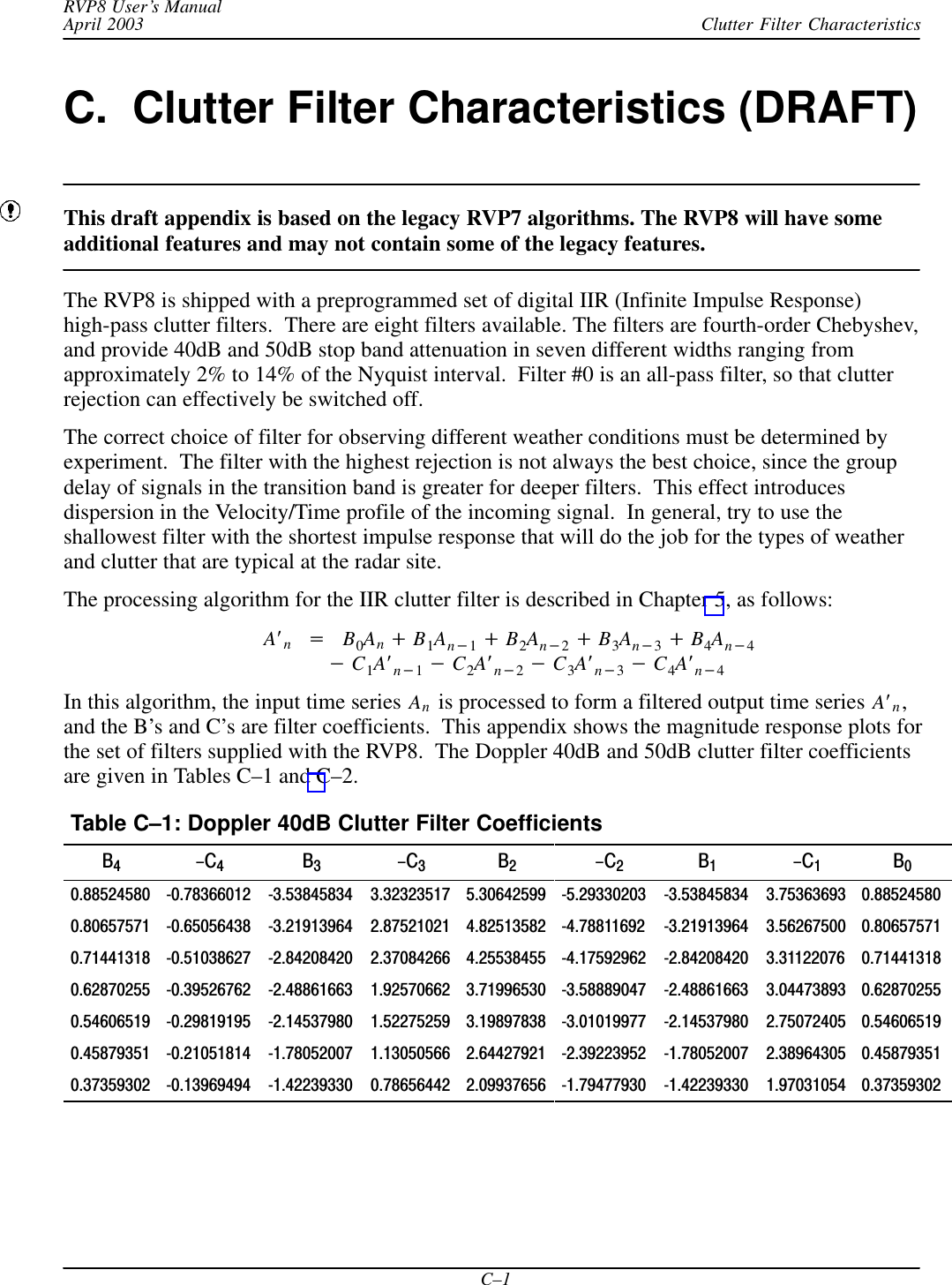
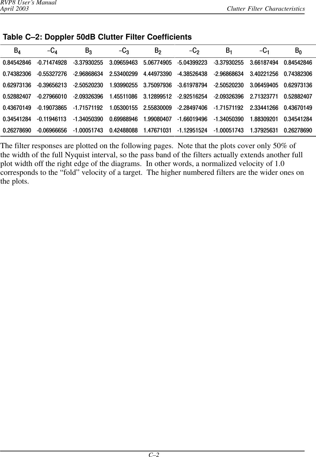
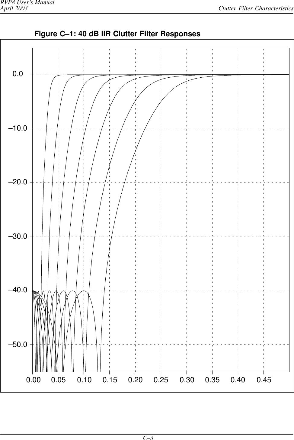
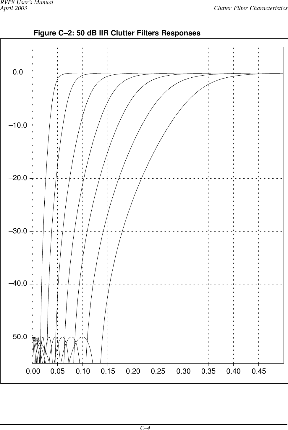
S10 RECEIVER AND PROCESSOR USERS MANUAL PART 3
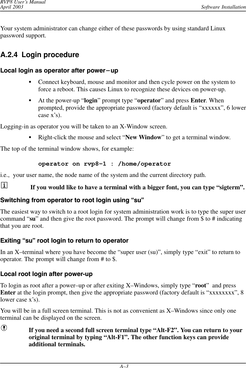

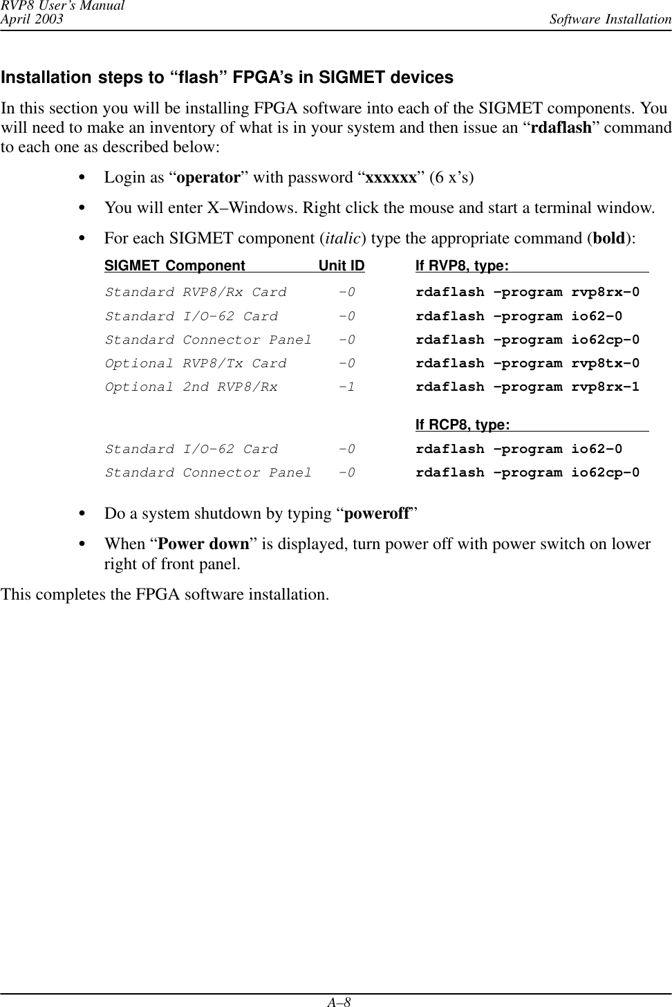
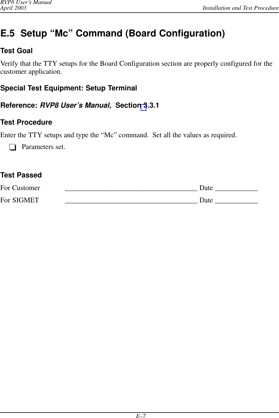
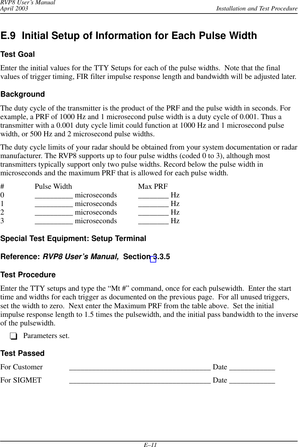
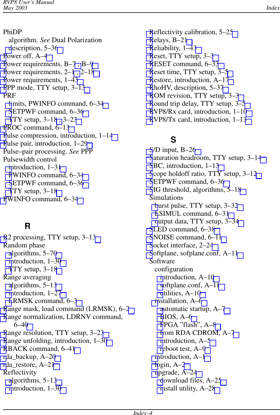
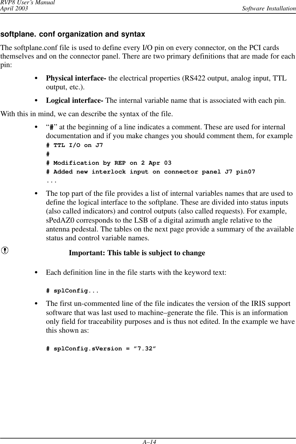
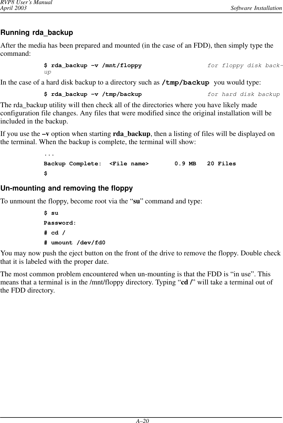
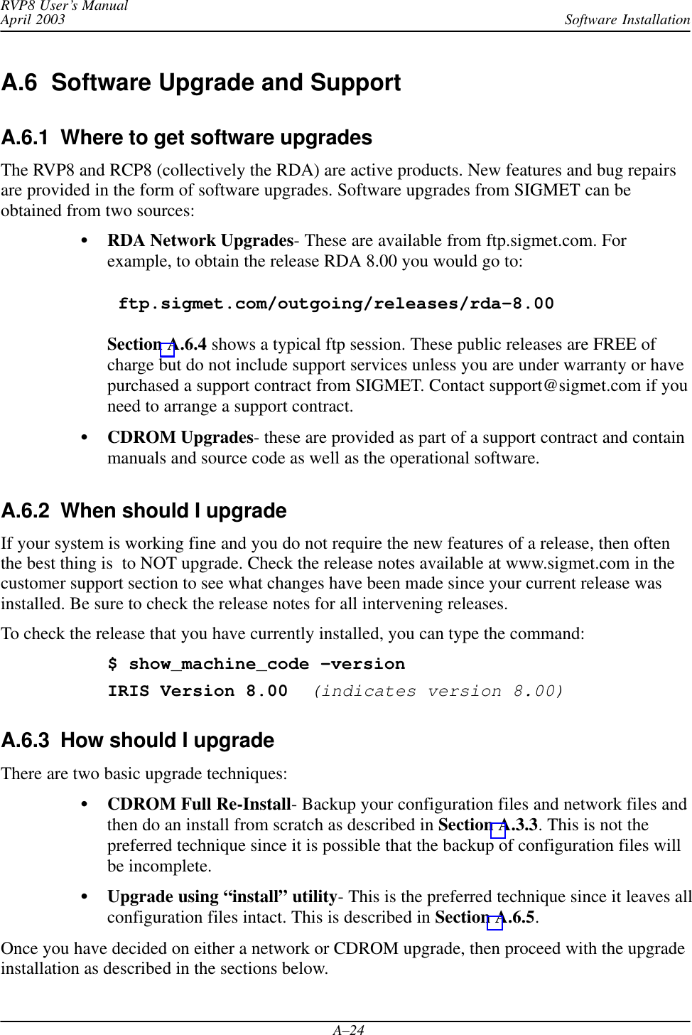
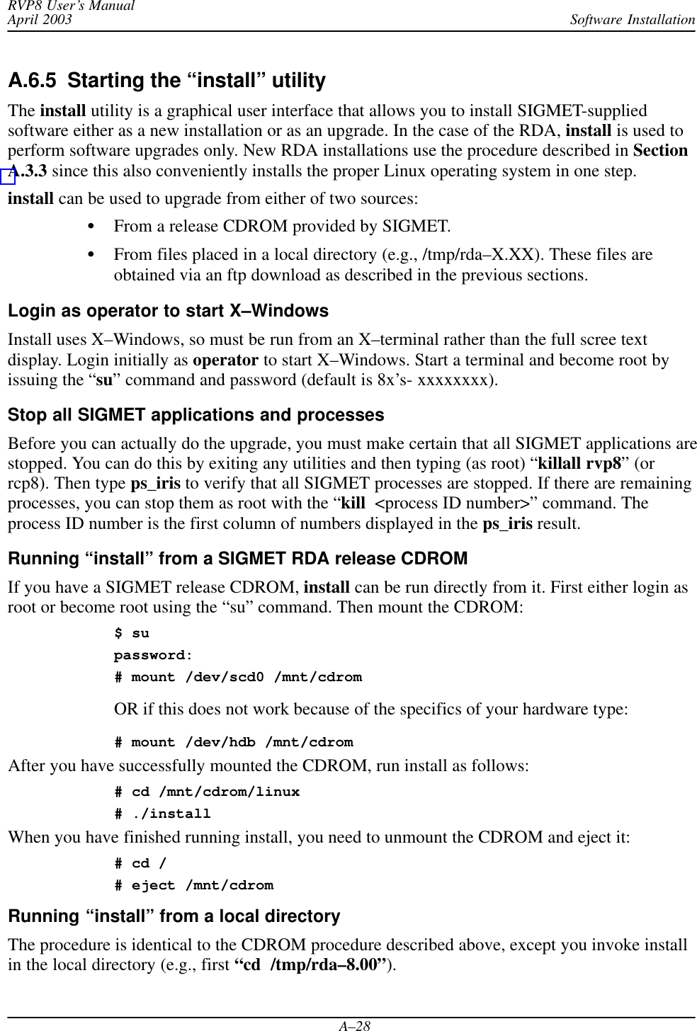
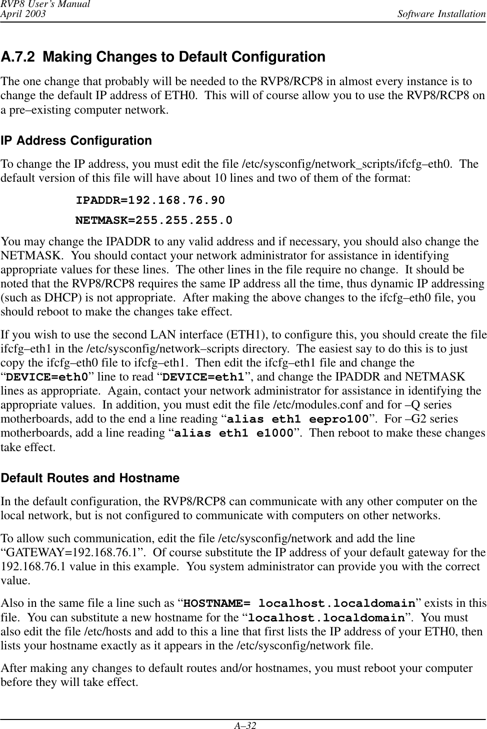
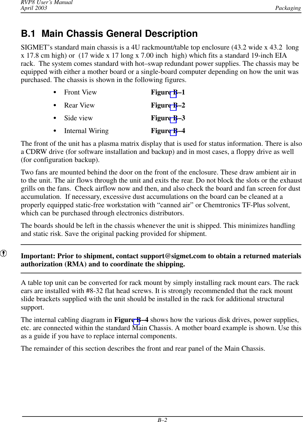
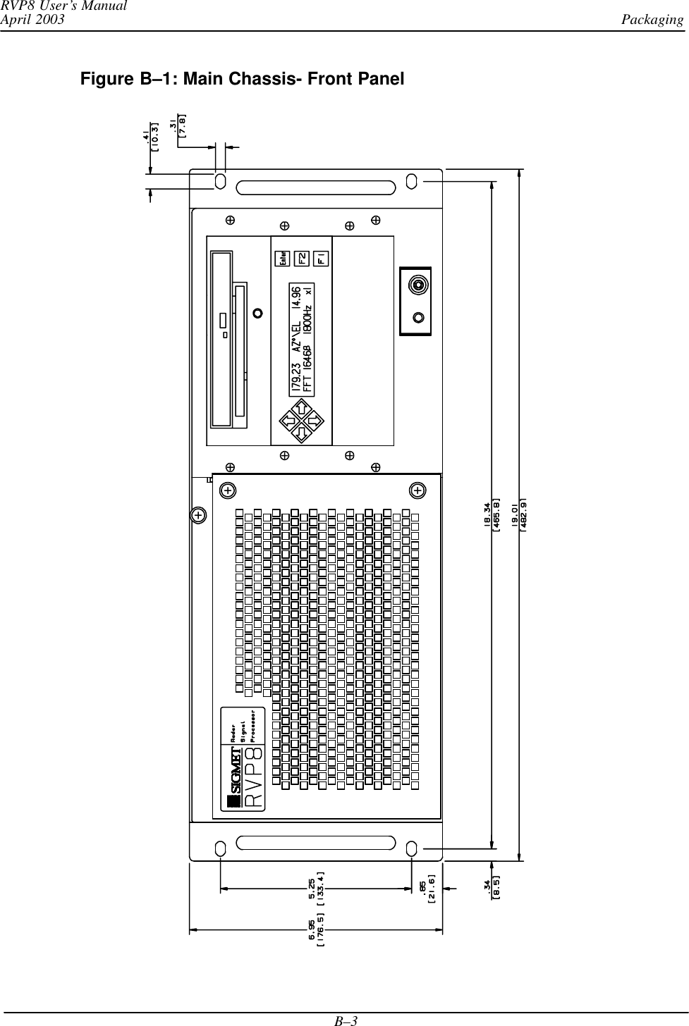
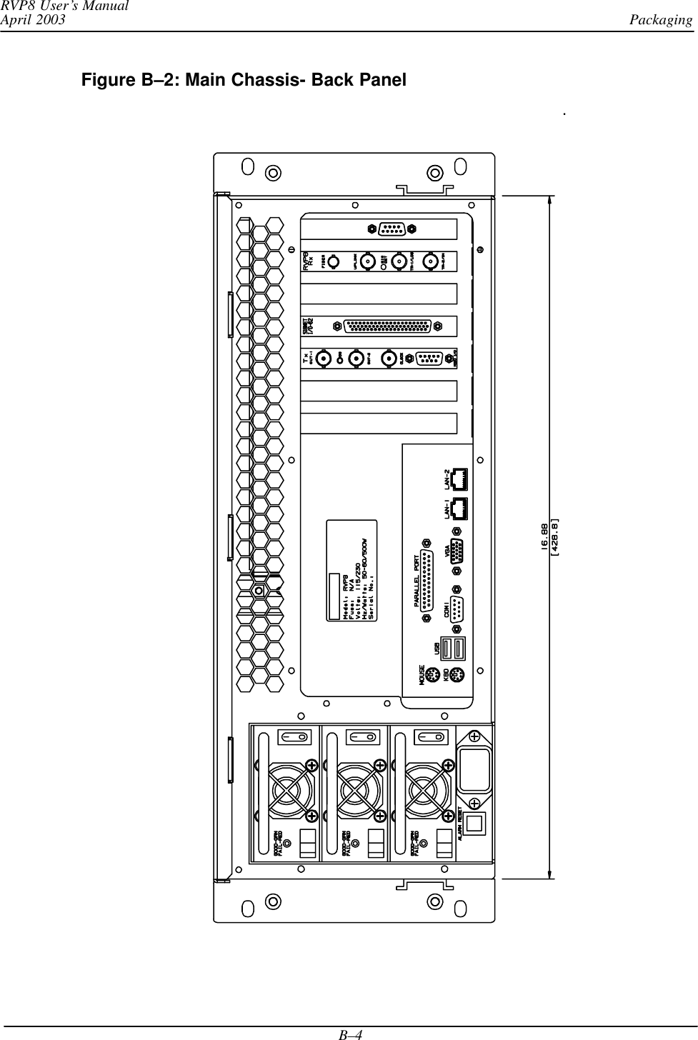
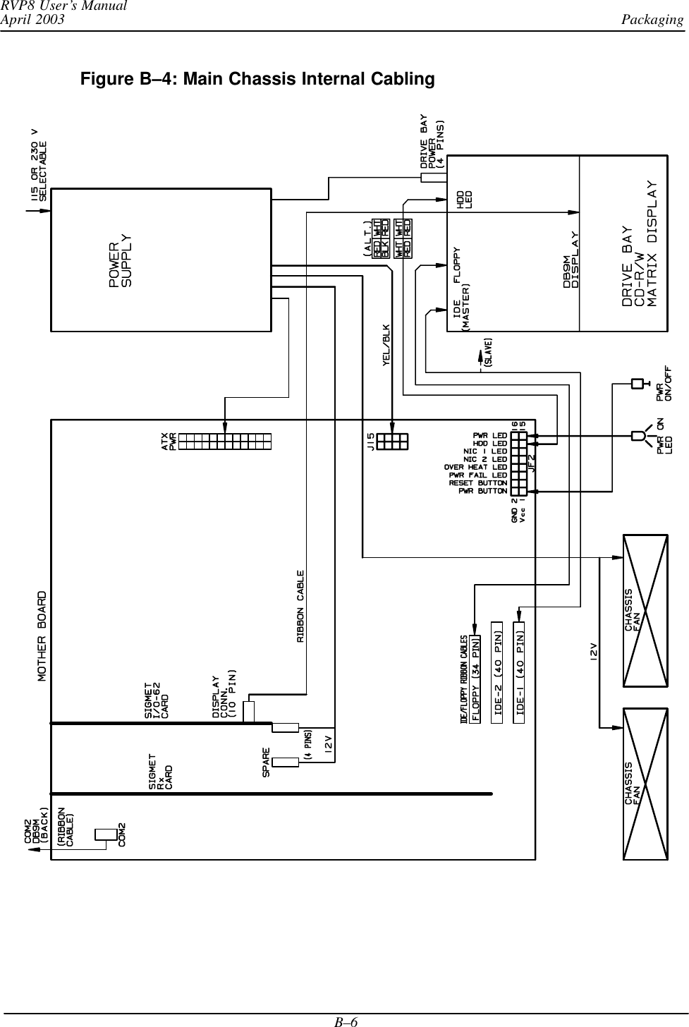
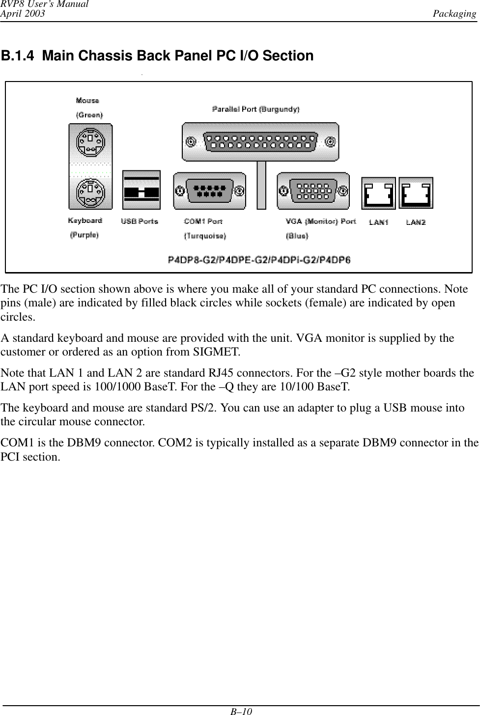
![Software InstallationRVP8 User’s ManualApril 2003A–12softplane.conf file exampleAn example from the beginning and some excerpts from the softplane.conf file are shown below(note that the command “cat” causes the file to be listed on a terminal):$ cat /usr/sigmet/config/softplane.conf# **********************************# * *# * Softplane Configuration File *# * *# **********************************# The following general purpose control and status signals# can be routed to/from any available hardware pin. The ’~’# prefix character may be used for signal inversion. ## Control Outputs Status Inputs# ––––––––––––––––– –––––––––––––––# cPedAZ[15:0] sPedAZ[15:0]# cPedEL[15:0] sPedEL[15:0]# cEarthAZ[15:0] sServoPwr# cEarthEL[15:0] sLocal# cServoPwr sStandby# cCabinetRelay sLowerEL# cTransmitPwr sUpperEL# cPWidth[3:0] sTransmitPwr# cTrigBlank sTransmitLocal# cRadiateOn sPWidth[3:0]# cRadiateOff sTrigBlank# cReset sRadiate# cIrisMode[2:0] sAirflowFlt# cAux[63:0] sWavegpFlt# true sInterlockFlt# false sMagCurrentFlt# sReset# sIrisMode[2:0]# sAux[319:0]splConfig.sVersion = ”7.32”# ––––––––––––––––––– IO62 Slot #0 –––––––––––––––––––#splConfig.Io62[0].lInUse = 1# The remote backpanel type should be one of the following:# Direct : Direct I/O with IO62 connector itself# IO62CP : Standard IO62–CP connector panel# RVP88D : RVP8 portion of WSR88D panel# RCP88D : RCP8 portion of WSR88D panel#splConfig.Io62[1].sExtPanel = ”IO62CP”# TTL/CMOS on J1#splConfig.Io62[0].Opt.Cp.J1.pin01 = ”sPedAZ[0]”splConfig.Io62[0].Opt.Cp.J1.pin02 = ”sPedAZ[1]”splConfig.Io62[0].Opt.Cp.J1.pin03 = ”sPedAZ[2]”...](https://usermanual.wiki/Baron-Weather/XDD-1000C.S10-RECEIVER-AND-PROCESSOR-USERS-MANUAL-PART-3/User-Guide-374024-Page-12.png)
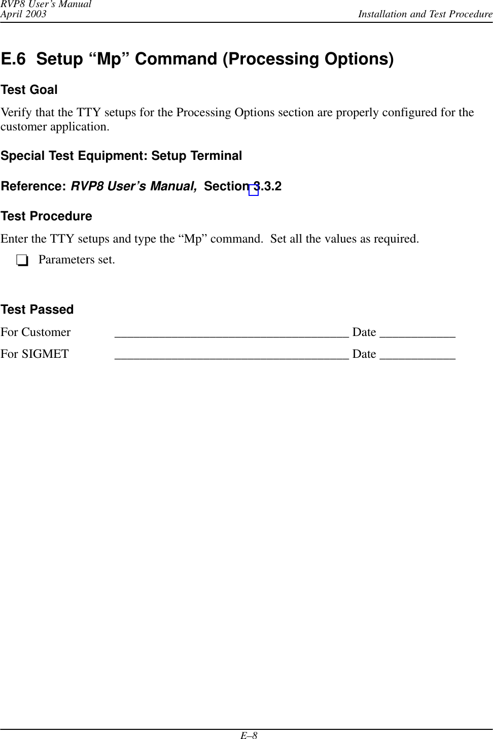
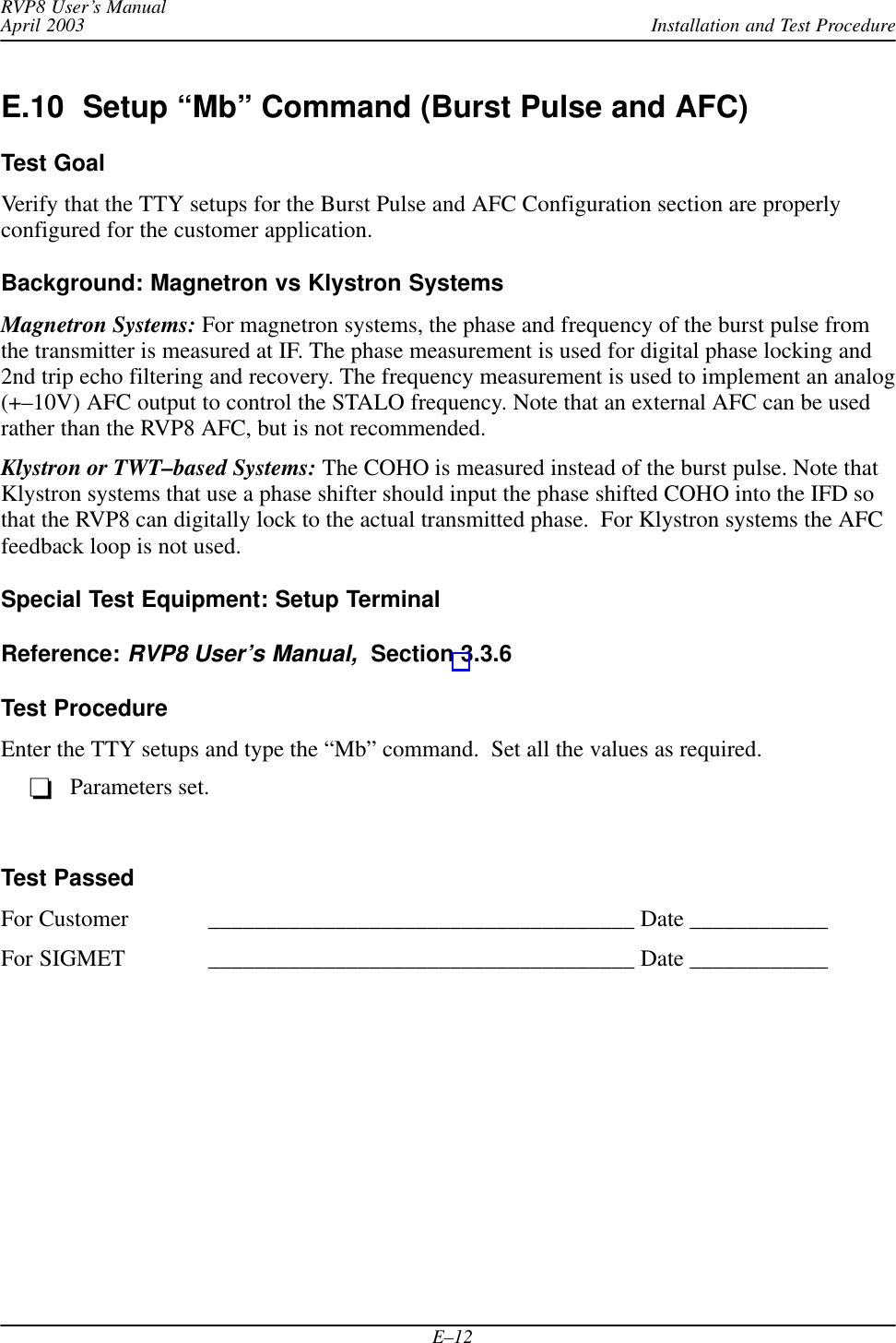
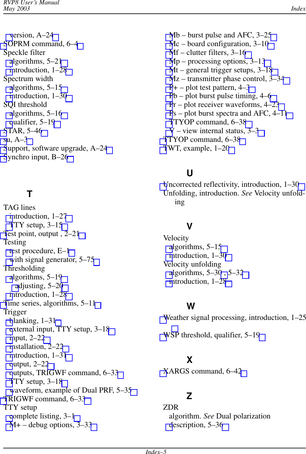
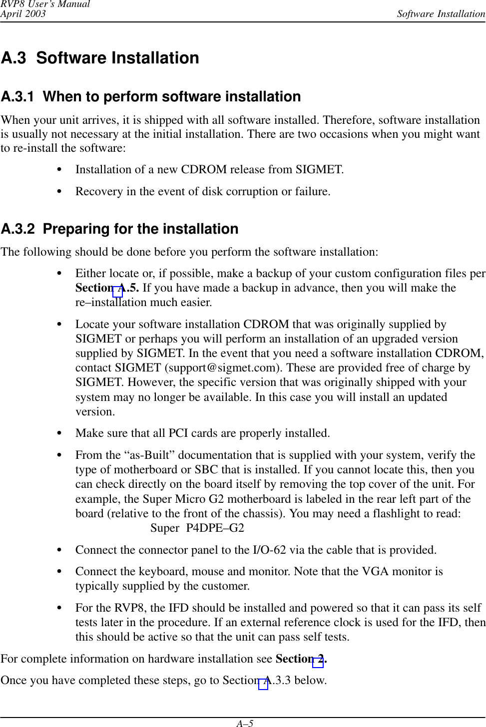
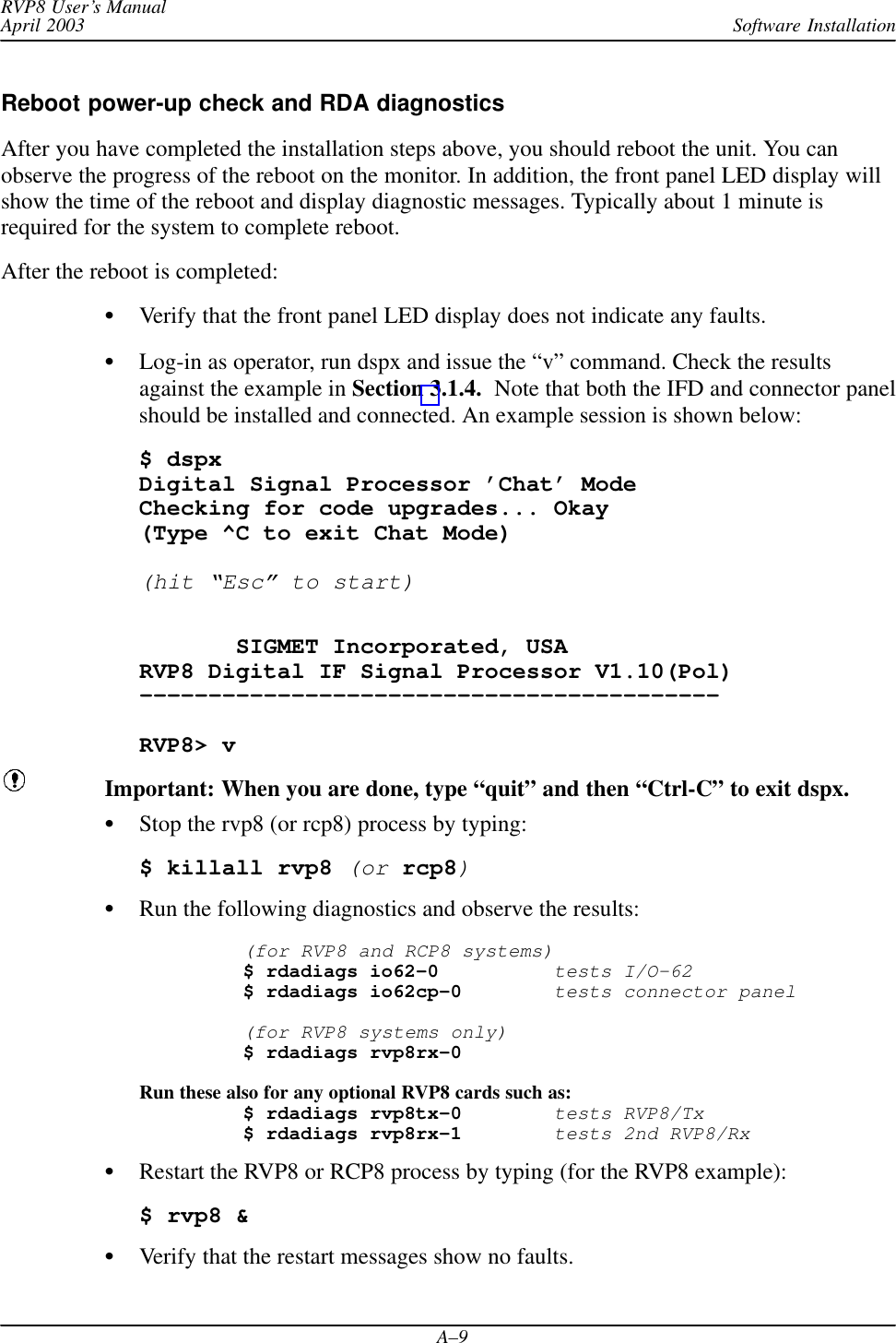
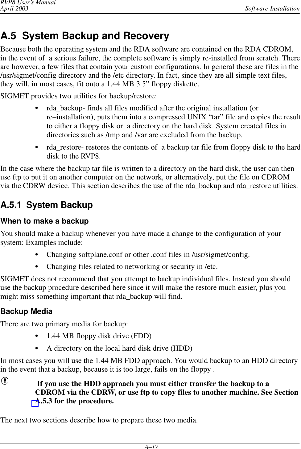
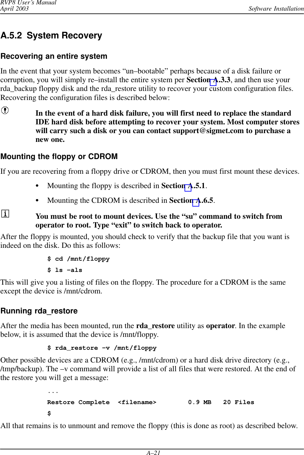
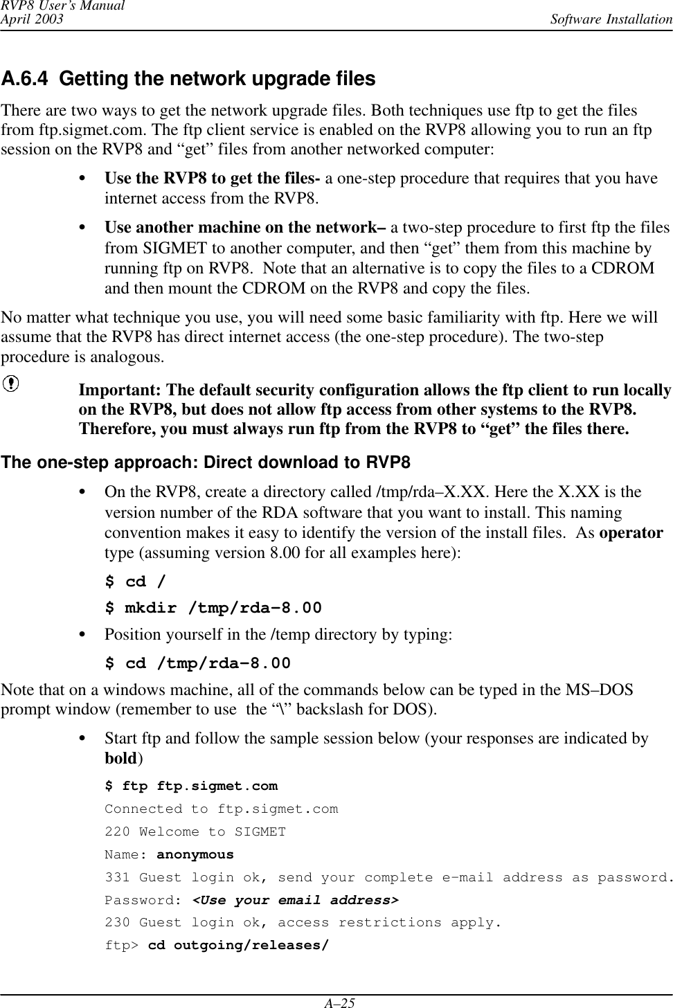
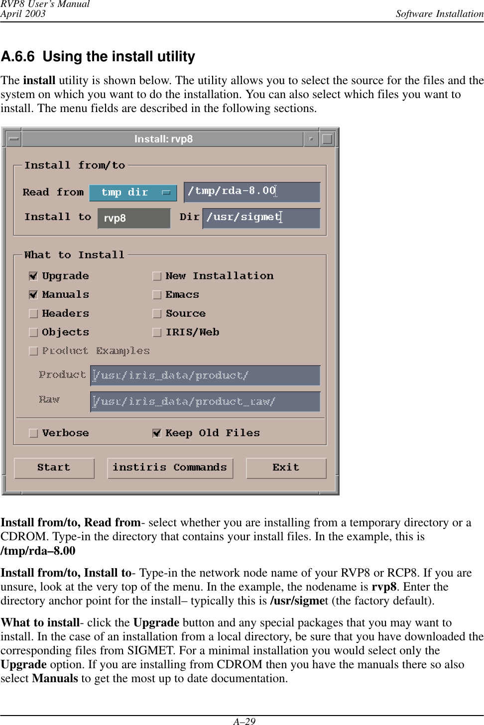
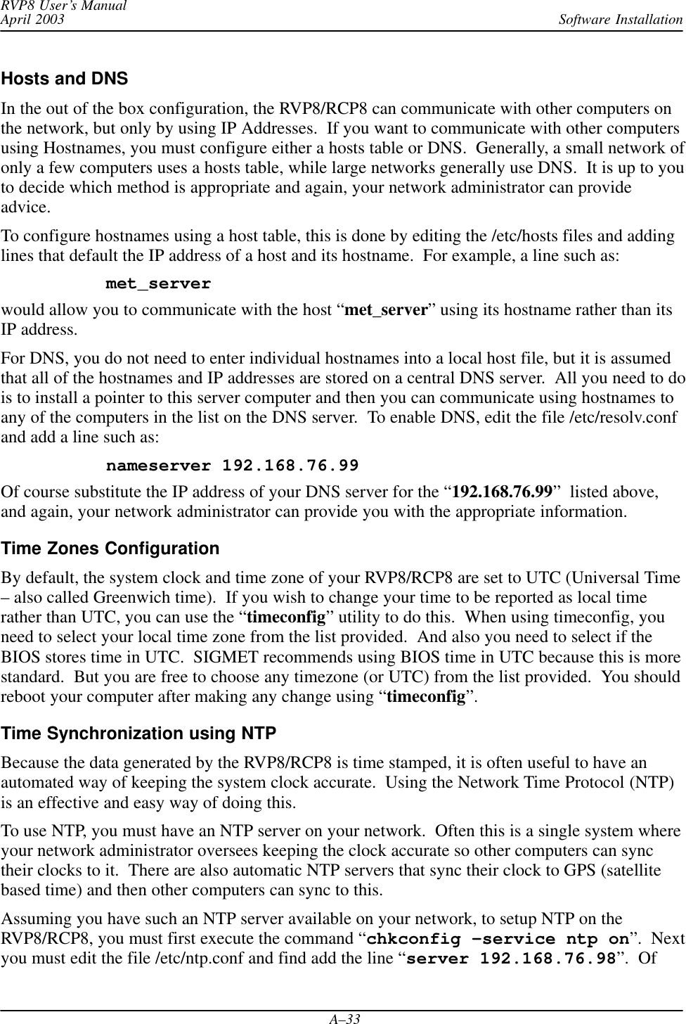
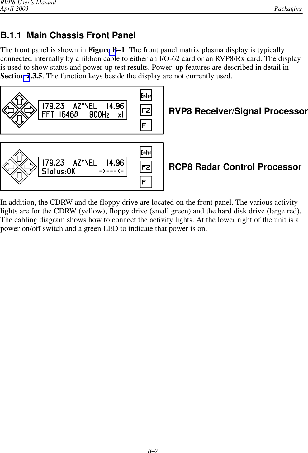
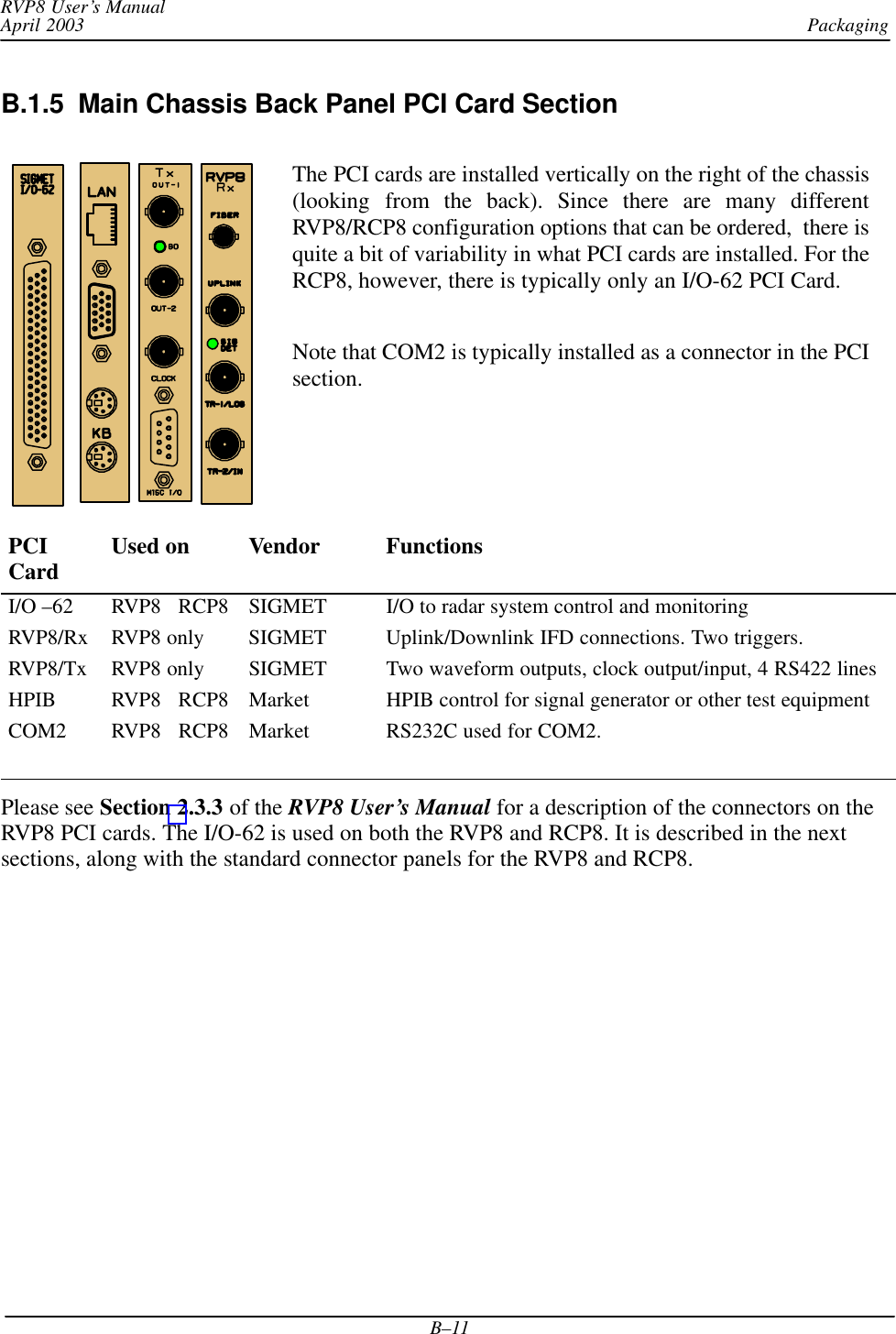
![Software InstallationRVP8 User’s ManualApril 2003A–13# Relays and relay drivers on J6#splConfig.Io62[0].Opt.Cp.J6_IntRelay1 = ””splConfig.Io62[0].Opt.Cp.J6_IntRelay2 = ””splConfig.Io62[0].Opt.Cp.J6_IntRelay3 = ””splConfig.Io62[0].Opt.Cp.J6_ExtRelay1 = ””splConfig.Io62[0].Opt.Cp.J6_ExtRelay2 = ””splConfig.Io62[0].Opt.Cp.J6_ExtRelay3 = ””splConfig.Io62[0].Opt.Cp.J6_ExtRelay4 = ””# BNC testpoint monitors#splConfig.Io62[0].Opt.Cp.J13_BNC = ””splConfig.Io62[0].Opt.Cp.J16_BNC = ””# BNC trigger drivers direct from IO62 PCI card.# Special signals ’trigger[8:1]’ may also be used here.#splConfig.Io62[0].Opt.Cp.J14_BNC = ””splConfig.Io62[0].Opt.Cp.J15_BNC = ””splConfig.Io62[0].Opt.Cp.J17_BNC = ””splConfig.Io62[0].Opt.Cp.J18_BNC = ””# RS232 TTY transmitters from IO62#splConfig.Io62[0].Opt.Cp.TTY0_Tx = ””splConfig.Io62[0].Opt.Cp.TTY1_Tx = ””# ––––––––––––––––––– IO62 Slot #1 –––––––––––––––––––#splConfig.Io62[1].lInUse = 0# ––––––––––––––––––– IO62 Slot #2 –––––––––––––––––––#splConfig.Io62[2].lInUse = 0....# <End of softplane definitions>](https://usermanual.wiki/Baron-Weather/XDD-1000C.S10-RECEIVER-AND-PROCESSOR-USERS-MANUAL-PART-3/User-Guide-374024-Page-13.png)
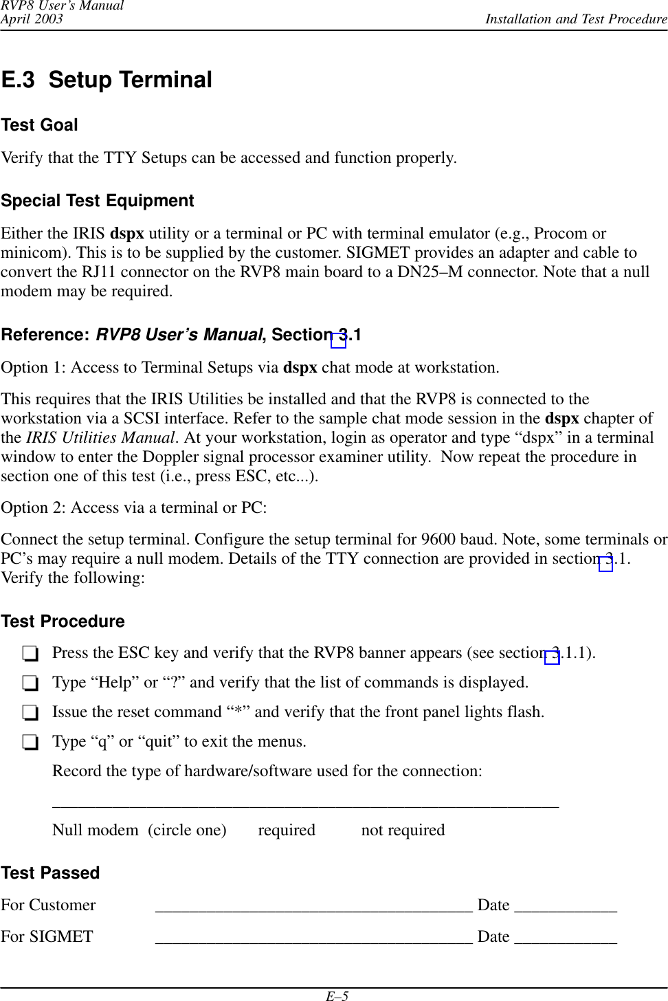
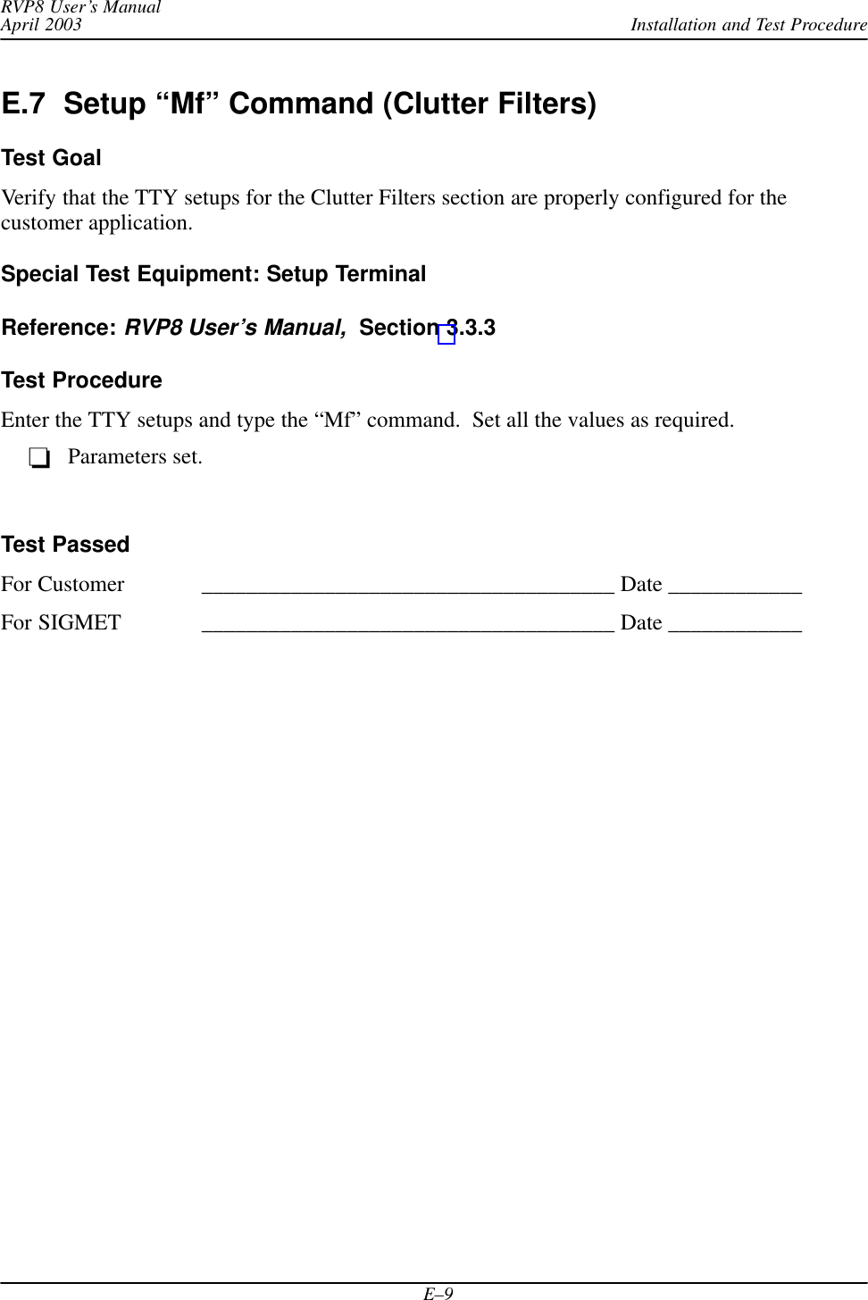
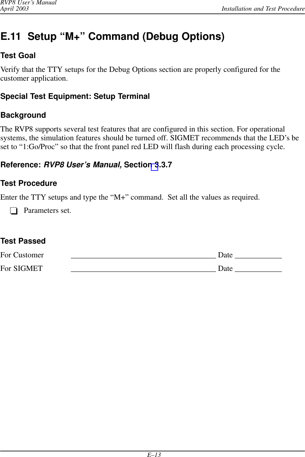
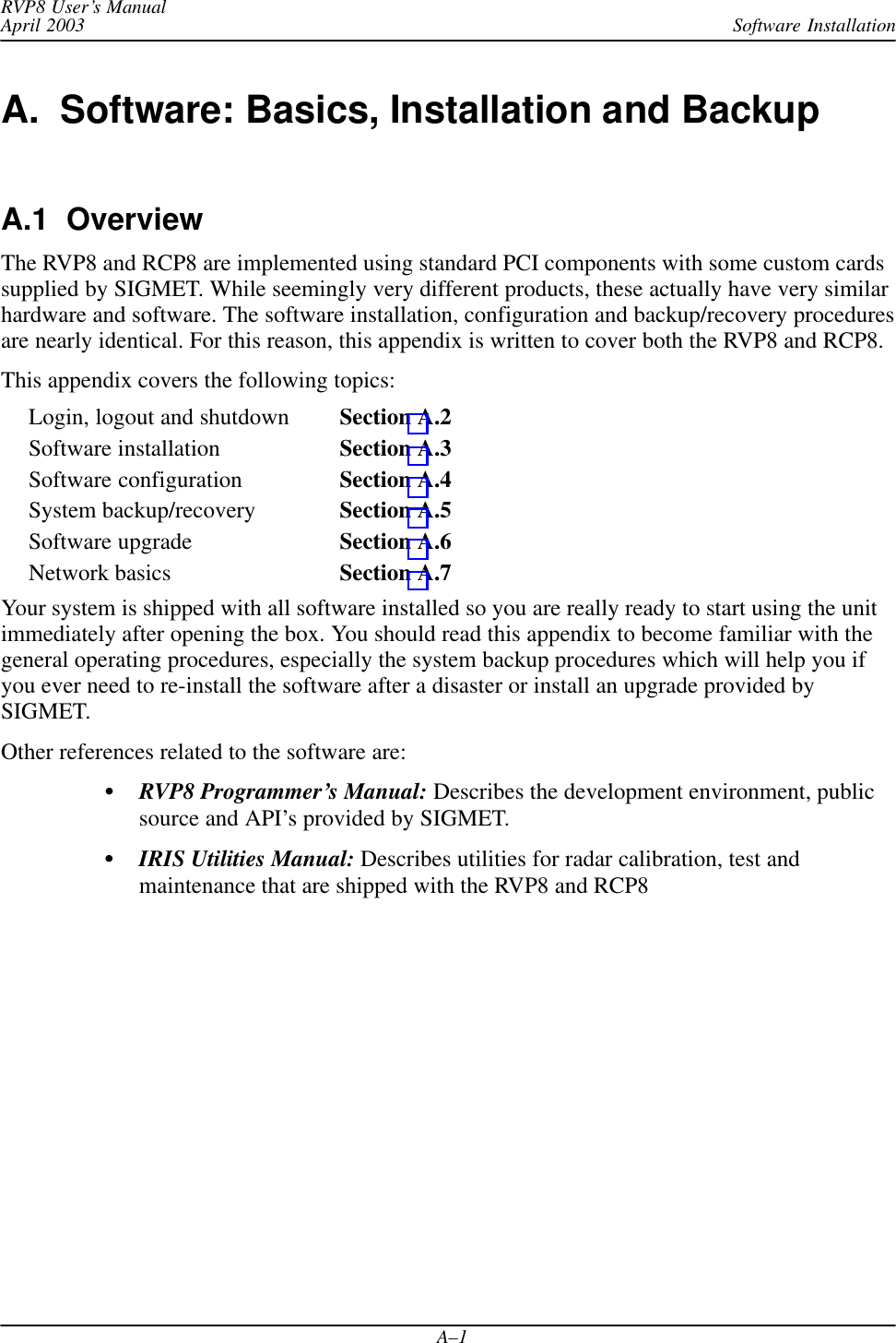
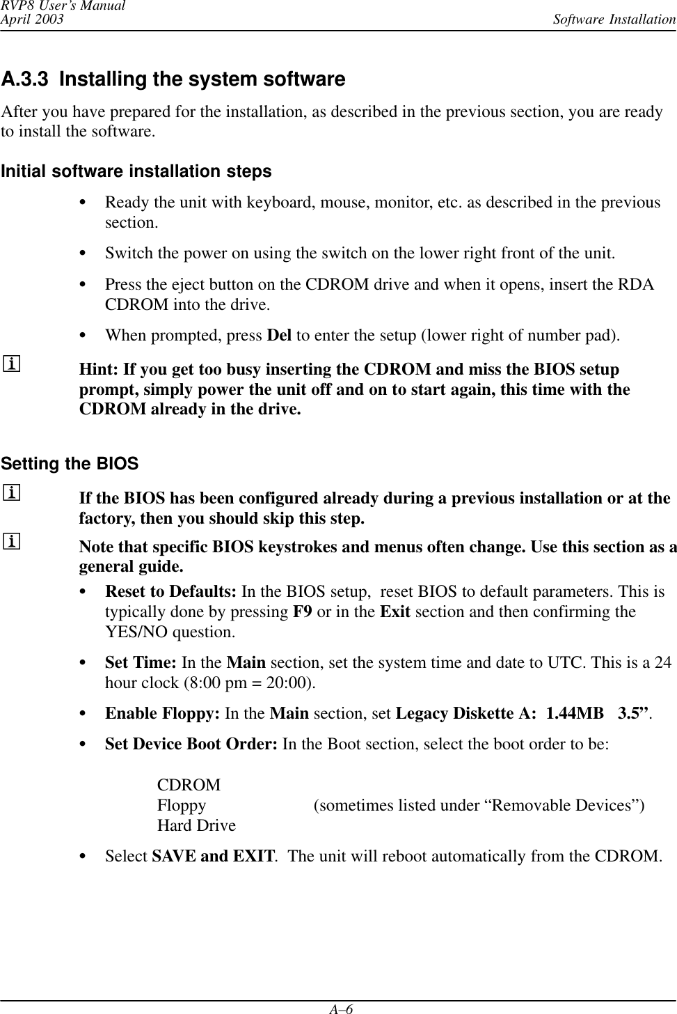
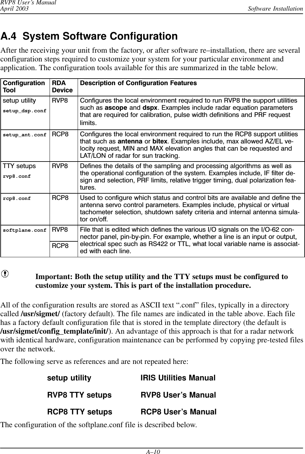
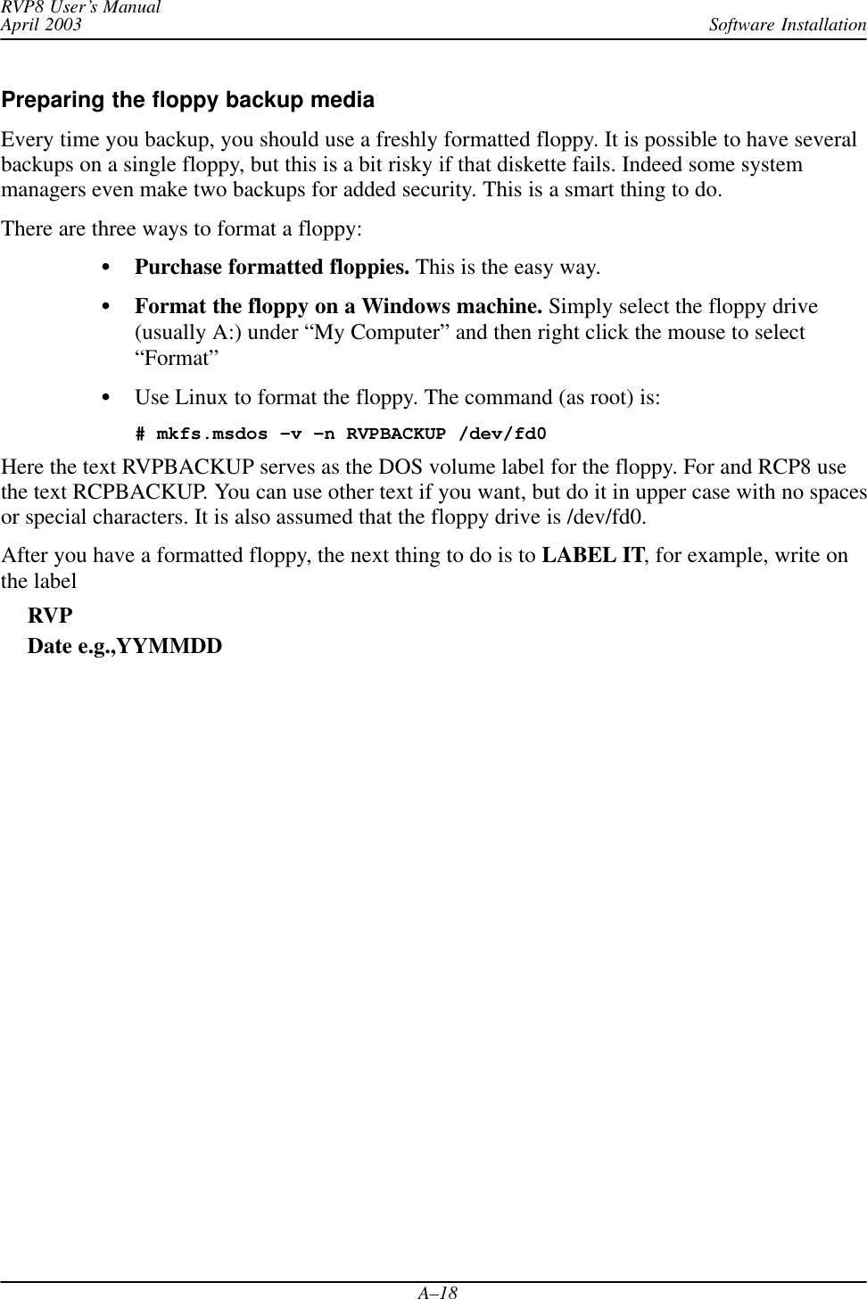
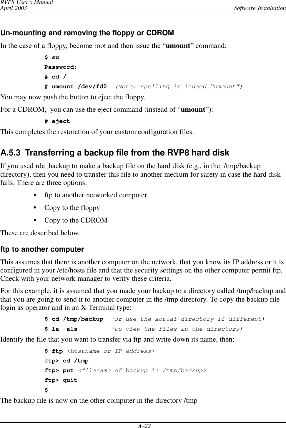
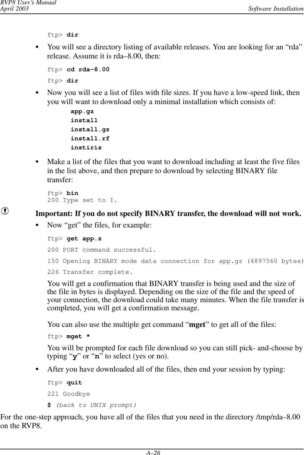
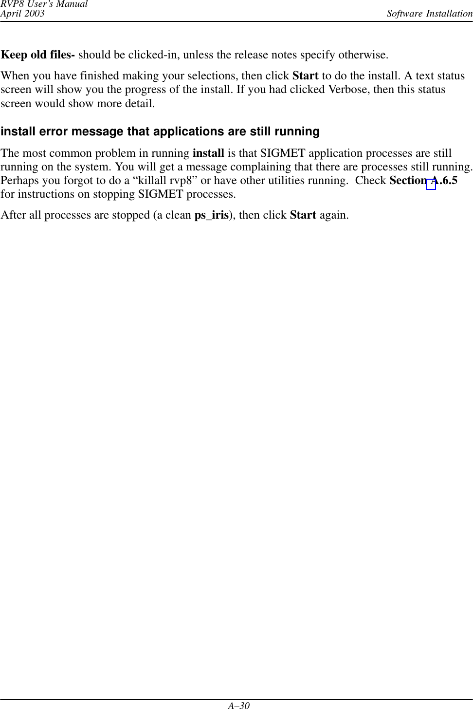
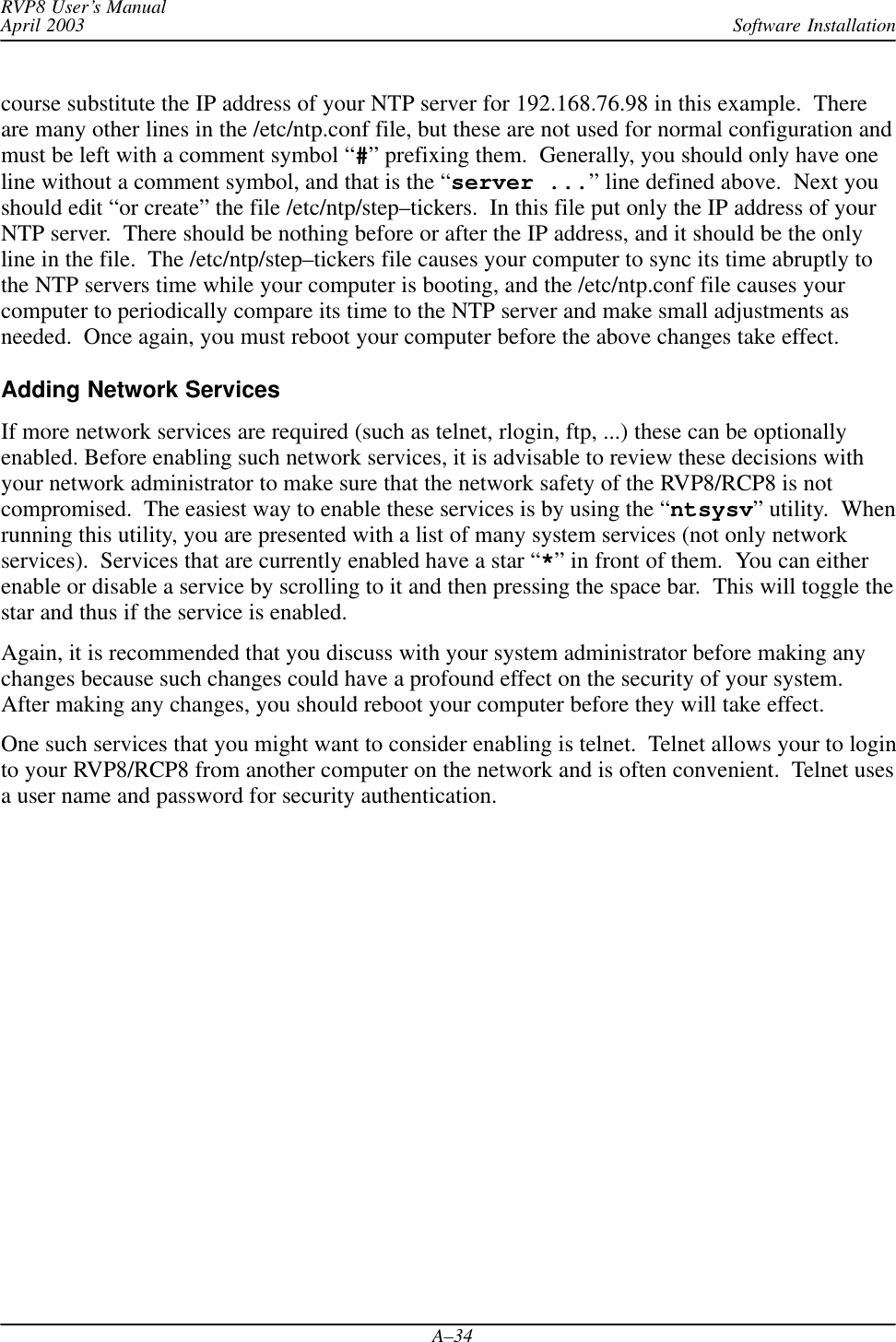
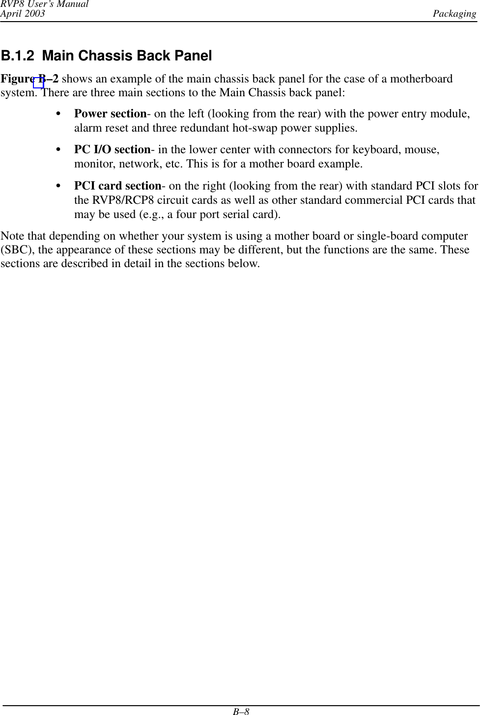
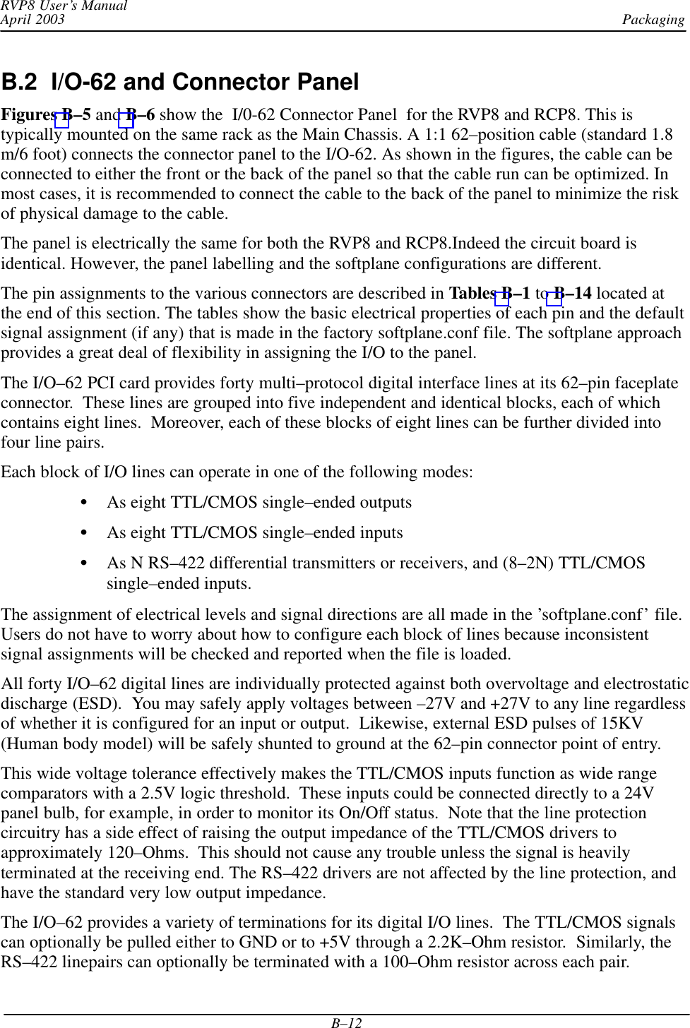
![Software InstallationRVP8 User’s ManualApril 2003A–15Summary of softplane.conf Status and Control BitsControl Output Meaning/InterpretationcPedAZ[15:0] 16 bits of antenna azimuth angle relative to the pedestal (fixed base system)cPedEL[15:0] 16 bits of antenna elevation angle relative to the pedestal (fixed base system)cEarthAZ[15:0] 16 bits of antenna azimuth angle relative to the earth (moving platform)cEarthEL[15:0] 16 bits of antenna elevation angle relative to the earth (moving platform)cServoPwr To control servo power oncCabinetRelay To control a relay signalcTransmitPwr Request transmit power oncPWidth[3:0] Request one of four pulse widthscTrigBlank Trigger blanking signalcRadiateOn Request radiate oncRadiateOff Request for radiate offcReset Request a reset of external equipmentcIrisMode[2:0] Request the application software (e.g., IRIS) to switch to 1 of 8 operating modes.cAux[63:0] Arbitrarily assigned output requeststrue Internal logic variablefalse Internal logic variableStatus Input Meaning/InterpretationsPedAZ[15:0] 16 bits of antenna azimuth angle relative to the pedestal (fixed base system)sPedEL[15:0] 16 bits of antenna elevation angle relative to the pedestal (fixed base system)sServoPwr Servo power on indicatorsLocal Antenna local mode indicator, usually tied to an external local/remote switch.sStandby Radar ready to radiate indicatorsLowerEL Lower limit switch indicatorsUpperEL Upper limit switch indicatorsTransmitPwr Transmitter cabinet power on indicatorsTransmitLocal Transmitter local mode indicator, usually tied to an external local/remote switch.sPWidth[3:0] Indicator of the current pulse widthsTrigBlank Indicator that trigger blanking is requested, usually from an external source.sRadiate Radiate on indicatorsAirflowFlt Cooling airflow fault indicatorsWavegpFlt Wave guide pressure fault indicatorsInterlockFlt Master interlock fault indicatorsMagCurrentFlt Transmitter overload fault indicatorsReset Request for reset coming from external sourcesIrisMode[2:0] Information on which operating mode is active in the application softwaresAux[319:0] Arbitrary status indicators](https://usermanual.wiki/Baron-Weather/XDD-1000C.S10-RECEIVER-AND-PROCESSOR-USERS-MANUAL-PART-3/User-Guide-374024-Page-15.png)
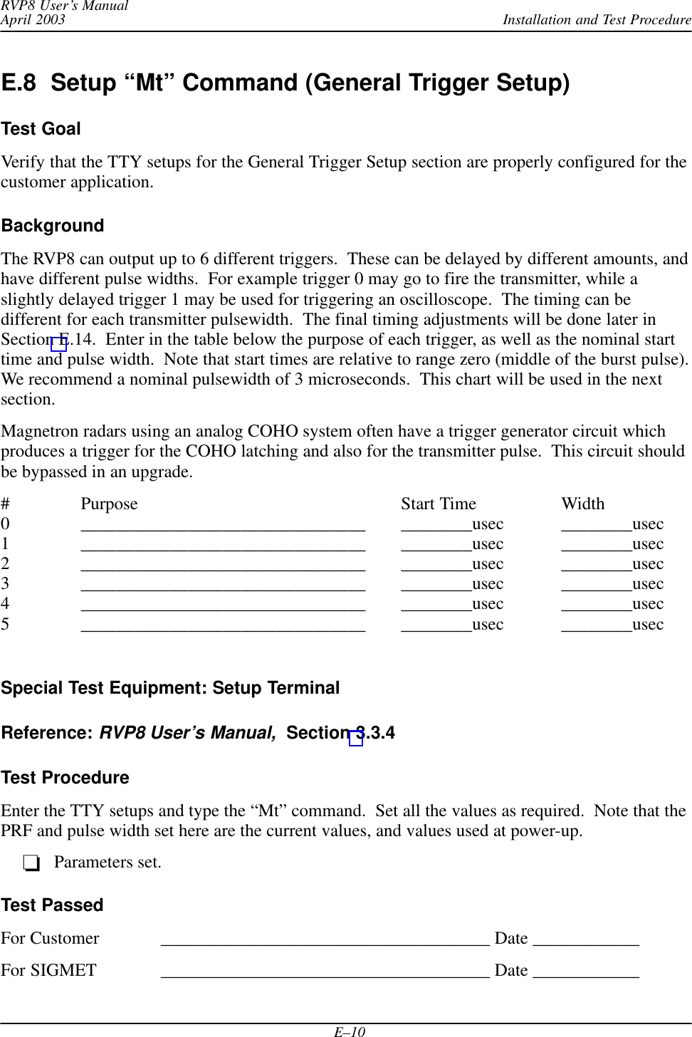
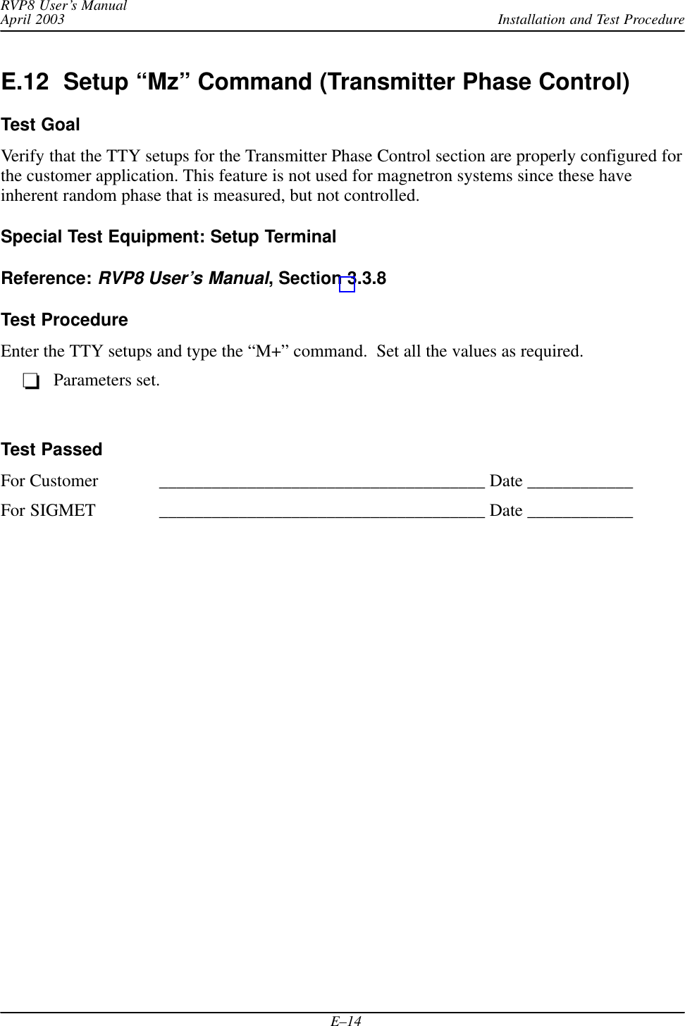
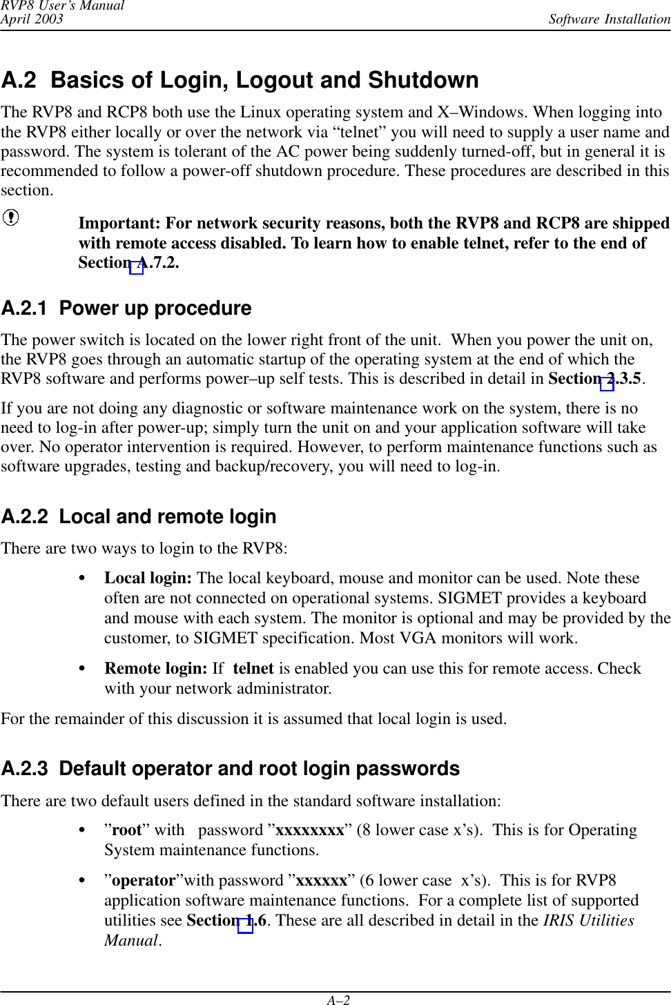
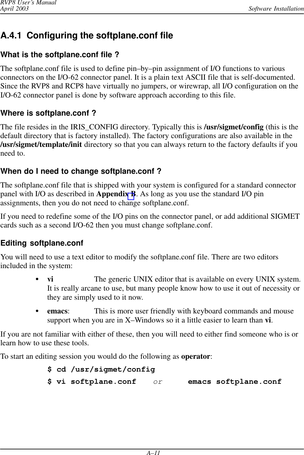
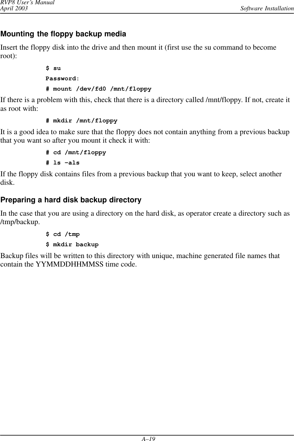
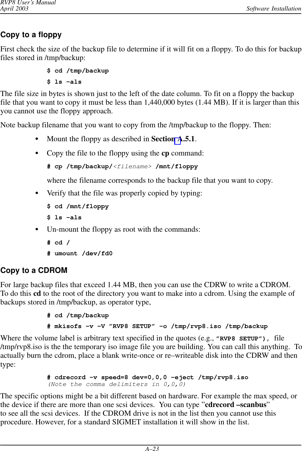
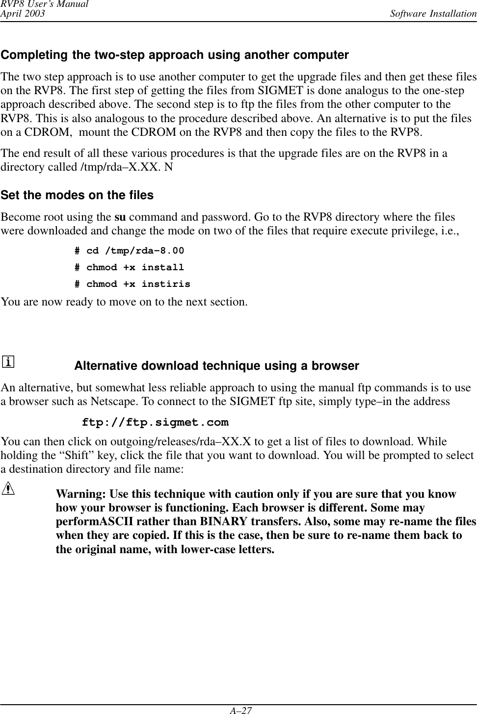
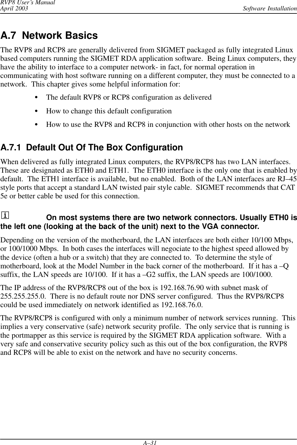
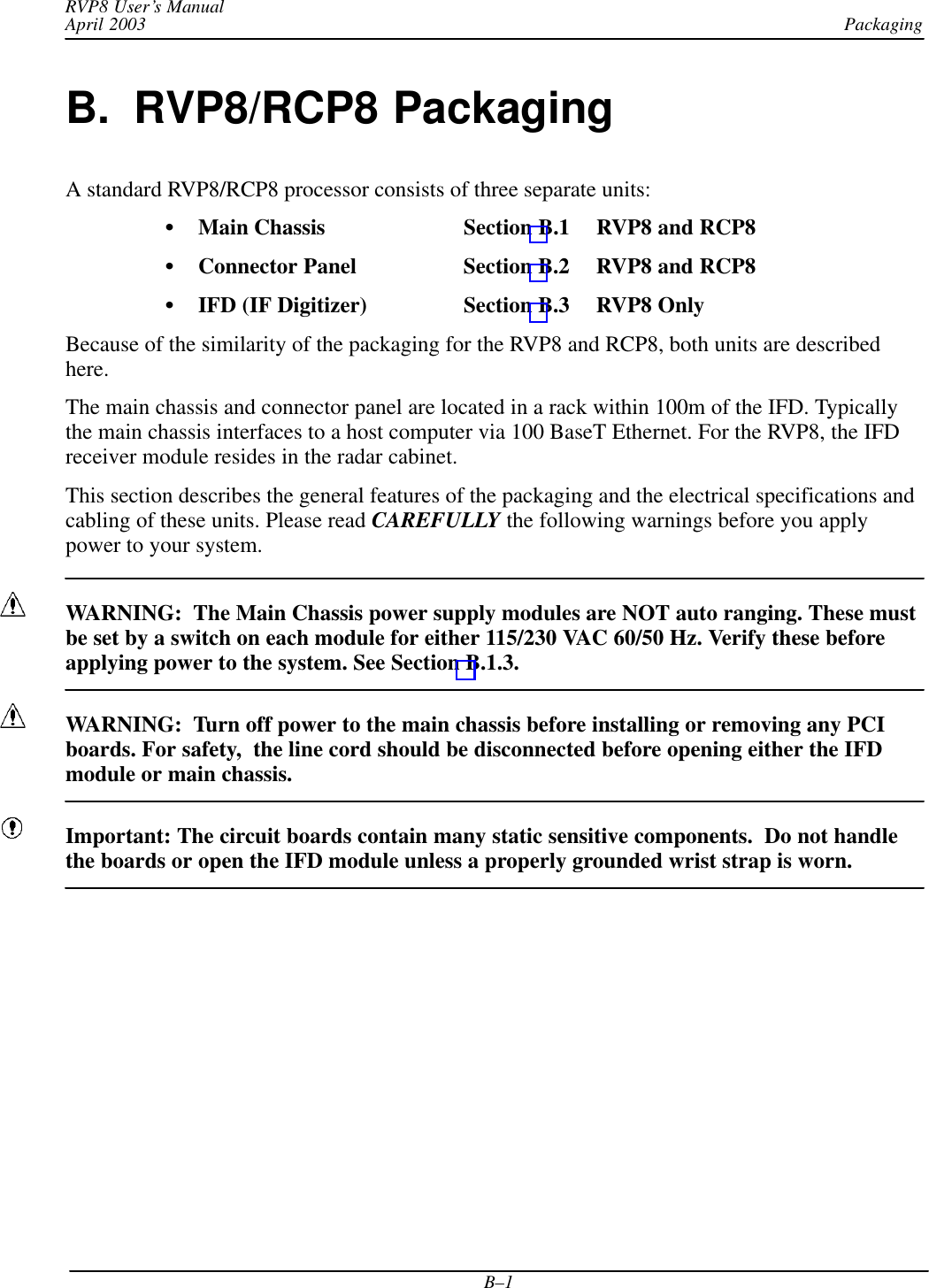
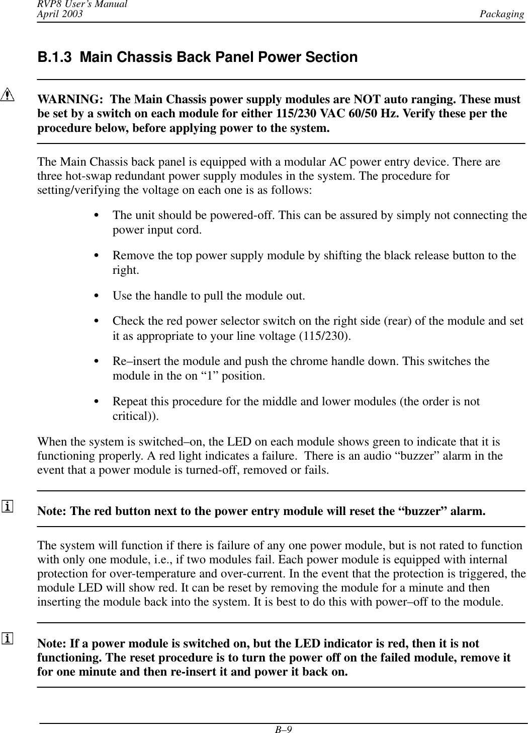
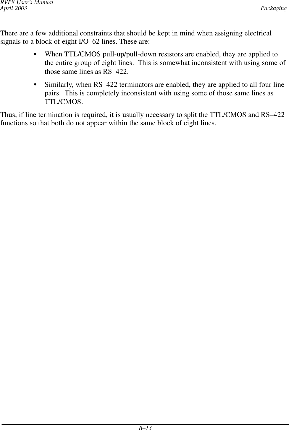
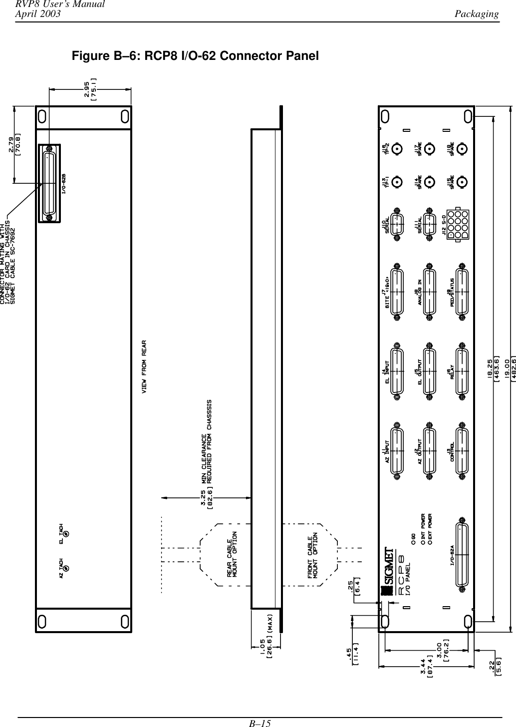
![Software InstallationRVP8 User’s ManualApril 2003A–16Next, each piece of hardware is identified as being either in use or not in use.splConfig.Io62[0].InUse = 1 if in usesplConfig.Io62[0].InUse = 0 if unused or not installedCurrently, the I/O-62 is the only I/O device supported by the softplane.The method of connecting to the I/O-62 is specified next, for example:splConfig.Io62[0].sExtPanel = ”DIRECT” Currently, the options are:Type of Connection softplaneDescriptorDirect connect to I/O-62 via 62 pin connector DIRECTI/O-62 Connector Panel (used for RVP8 and RCP8) IO62CPWSR88D connector panel, RVP8 portion RVP88DWSR88D connector panel, RCP8 portion RCP88DThe assignments for each connector and each pin are then made. Forconvenience, these are usually grouped together by connector. For example let’ssay that , Pin 1 of connector J1 on the I/O-62 connector panel is assigned to bethe LSB of the input azimuth angle, i.e.,# TTL/CMOS on J1#splConfig.Io62[0].Opt.Cp.J1.pin01 = ”sPedAZ[0]”...The notation ”” indicates that no assignment is made.# BNC testpoint monitors#splConfig.Io62[0].Opt.Cp.J13_BNC = ””In the example above the “pin name” is J13_BNC.Putting a ~ in front of a logic variable inverts the variable.splConfig.Io62[0].Opt.Cp.J1.pin03 = ”~sPedAZ[2]”Check in the /usr/sigmet/config_template/init directory for other examples of softplaneconfigurations.](https://usermanual.wiki/Baron-Weather/XDD-1000C.S10-RECEIVER-AND-PROCESSOR-USERS-MANUAL-PART-3/User-Guide-374024-Page-16.png)
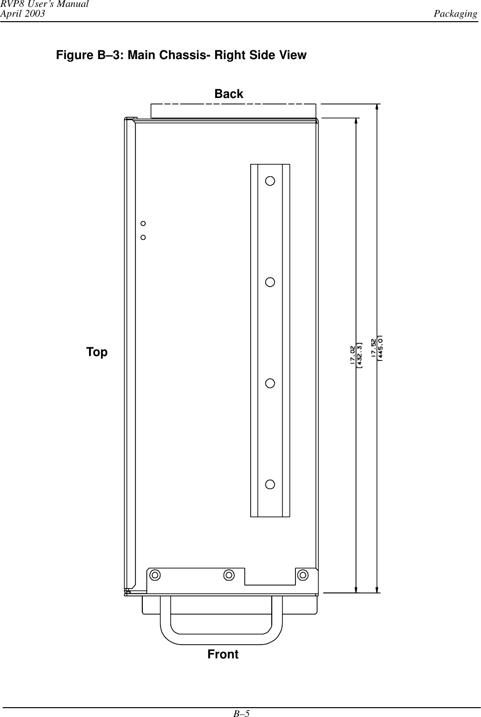

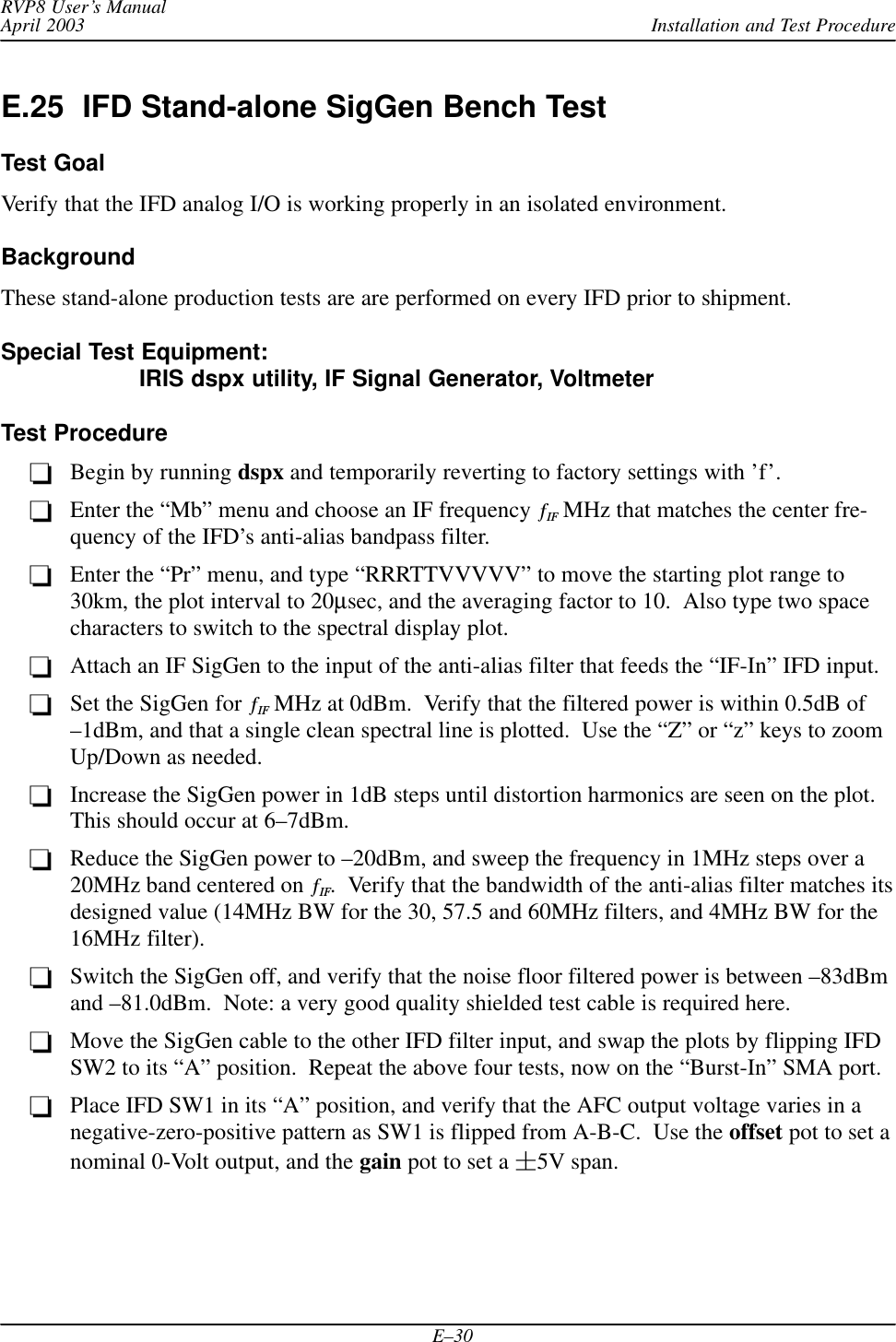
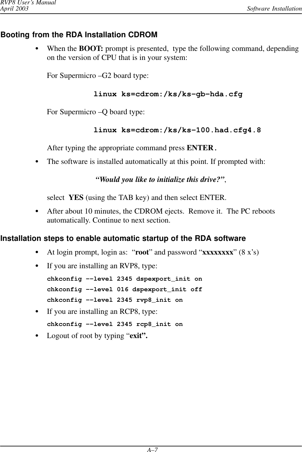
![PackagingRVP8 User’s ManualApril 2003B–16Table B–1: J1 “AZ INPUT” Pin Electrical Specification RVP8 Signal Name RCP8 Signal Name1 TTL sPedAZ[0] sPedAZ[0]2 TTL sPedAZ[1] sPedAZ[1]3 TTL sPedAZ[2] sPedAZ[2]4 TTL sPedAZ[3] sPedAZ[3]5 TTL sPedAZ[4] sPedAZ[4]6 TTL sPedAZ[5] sPedAZ[5]7 TTL sPedAZ[6] sPedAZ[6]8 TTL sPedAZ[7] sPedAZ[7]9 TTL sPedAZ[8] sPedAZ[8]10 TTL sPedAZ[9] sPedAZ[9]11 TTL sPedAZ[10] sPedAZ[10]12 TTL sPedAZ[11] sPedAZ[11]13 TTL sPedAZ[12] sPedAZ[12]14 TTL sPedAZ[13] sPedAZ[13]15 TTL sPedAZ[14] sPedAZ[14]16 TTL sPedAZ[15] sPedAZ[15]17 TTL18 TTL19 TTL20 TTL21 GND22 GND23 GND24 GND25 GND](https://usermanual.wiki/Baron-Weather/XDD-1000C.S10-RECEIVER-AND-PROCESSOR-USERS-MANUAL-PART-3/User-Guide-374024-Page-50.png)
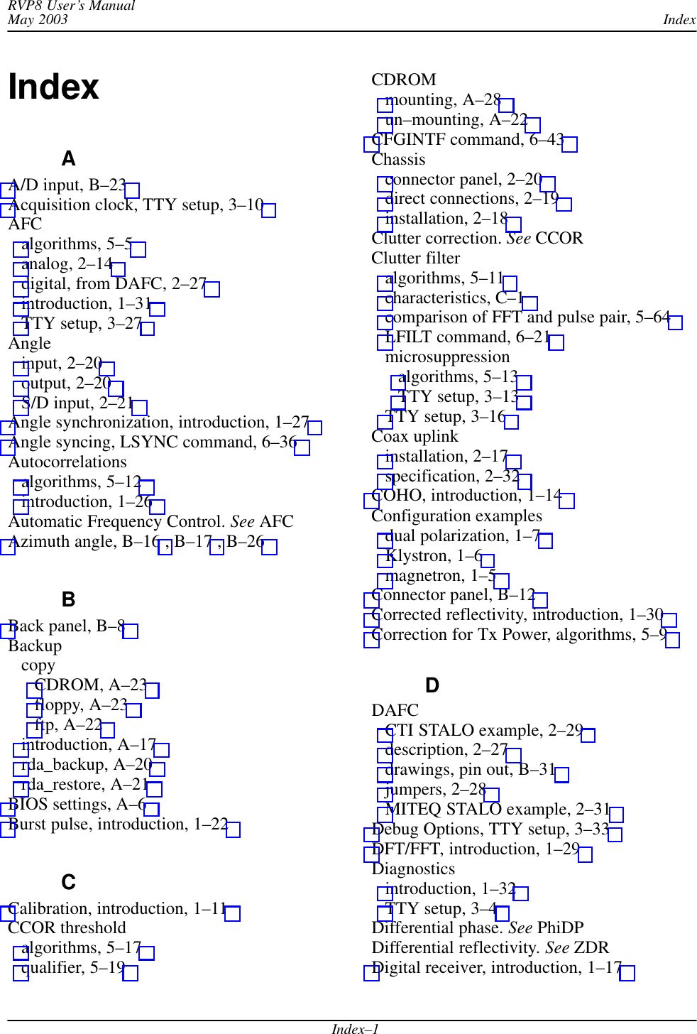
![PackagingRVP8 User’s ManualApril 2003B–17Table B–2: J2 “AZ OUTPUT”Pin Electrical Specification RVP8 Signal Name RCP8 Signal Name1 TTL cPedAZ[0] cPedAZ[0]2 TTL cPedAZ[1] cPedAZ[1]3 TTL cPedAZ[2] cPedAZ[2]4 TTL cPedAZ[3] cPedAZ[3]5 TTL cPedAZ[4] cPedAZ[4]6 TTL cPedAZ[5] cPedAZ[5]7 TTL cPedAZ[6] cPedAZ[6]8 TTL cPedAZ[7] cPedAZ[7]9 TTL cPedAZ[8] cPedAZ[8]10 TTL cPedAZ[9] cPedAZ[9]11 TTL cPedAZ[10] cPedAZ[10]12 TTL cPedAZ[11] cPedAZ[11]13 TTL cPedAZ[12] cPedAZ[12]14 TTL cPedAZ[13] cPedAZ[13]15 TTL cPedAZ[14] cPedAZ[14]16 TTL cPedAZ[15] cPedAZ[15]17 TTL18 TTL19 TTL20 TTL21 GND22 GND23 GND24 GND25 GND](https://usermanual.wiki/Baron-Weather/XDD-1000C.S10-RECEIVER-AND-PROCESSOR-USERS-MANUAL-PART-3/User-Guide-374024-Page-51.png)
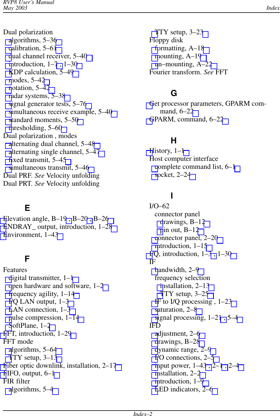
![PackagingRVP8 User’s ManualApril 2003B–18Table B–3: J3 RVP8: “PHASE OUT”; RCP8 “CONTROL” Pin Electrical Specification RVP8 Signal Name RCP8 Signal Name12 Configurable3gI/O–624Digital5Lines6789 RS422+ RS422+[0]10 RS422+ RS422+[1]11 GND12 GND13 GND1415 Configurable16gI/O–6217 Digital18 Lines19202122 RS422– RS422–[0]23 RS422– RS422–[1]24 GND25 GND](https://usermanual.wiki/Baron-Weather/XDD-1000C.S10-RECEIVER-AND-PROCESSOR-USERS-MANUAL-PART-3/User-Guide-374024-Page-52.png)
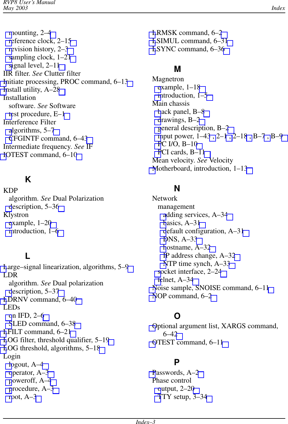
![PackagingRVP8 User’s ManualApril 2003B–19Table B–4: J4 “EL INPUT” Pin Electrical Specification RVP8 Signal Name RCP8 Signal Name1 TTL sPedEL[0] sPedEL[0]2 TTL sPedEL[1] sPedEL[1]3 TTL sPedEL[2] sPedEL[2]4 TTL sPedEL[3] sPedEL[3]5 TTL sPedEL[4] sPedEL[4]6 TTL sPedEL[5] sPedEL[5]7 TTL sPedEL[6] sPedEL[6]8 TTL sPedEL[7] sPedEL[7]9 TTL sPedEL[8] sPedEL[8]10 TTL sPedEL[9] sPedEL[9]11 TTL sPedEL[10] sPedEL[10]12 TTL sPedEL[11] sPedEL[11]13 TTL sPedEL[12] sPedEL[12]14 TTL sPedEL[13] sPedEL[13]15 TTL sPedEL[14] sPedEL[14]16 TTL sPedEL[15] sPedEL[15]17 TTL18 TTL19 TTL20 TTL21 GND22 GND23 GND24 GND25 GND](https://usermanual.wiki/Baron-Weather/XDD-1000C.S10-RECEIVER-AND-PROCESSOR-USERS-MANUAL-PART-3/User-Guide-374024-Page-53.png)
![PackagingRVP8 User’s ManualApril 2003B–20Table B–5: J5 “EL OUTPUT” Pin Electrical Specification RVP8 Signal Name RCP8 Signal NamePin Electrical Specification RVP8 Signal Name RCP8 Signal Name1 TTL cPedEL[0] cPedEL[0]2 TTL cPedEL[1] cPedEL[1]3 TTL cPedEL[2] cPedEL[2]4 TTL cPedEL[3] cPedEL[3]5 TTL cPedEL[4] cPedEL[4]6 TTL cPedEL[5] cPedEL[5]7 TTL cPedEL[6] cPedEL[6]8 TTL cPedEL[7] cPedEL[7]9 TTL cPedEL[8] cPedEL[8]10 TTL cPedEL[9] cPedEL[9]11 TTL cPedEL[10] cPedEL[10]12 TTL cPedEL[11] cPedEL[11]13 TTL cPedEL[12] cPedEL[12]14 TTL cPedEL[13] cPedEL[13]15 TTL cPedEL[14] cPedEL[14]16 TTL cPedEL[15] cPedEL[15]17 TTL18 TTL19 TTL20 TTL21 GND22 GND23 GND24 GND25 GND](https://usermanual.wiki/Baron-Weather/XDD-1000C.S10-RECEIVER-AND-PROCESSOR-USERS-MANUAL-PART-3/User-Guide-374024-Page-54.png)
![PackagingRVP8 User’s ManualApril 2003B–21Table B–6: J6 “RELAY” Pin ElectricalSpecification RVP8 Signal Name RCP8 Signal Name1Relay K1: CT Internal Relay Center Contact2Relay K1: NO Internal Relay Normally Open cPWidth[0]3Relay K1: NC Internal Relay Normally Closed4 Relay K2: CT Internal Relay Center Contact5 Relay K2: NO Internal Relay Normally Open cPWidth[1]6 Relay K2: NC Internal Relay Normally Closed7Relay K3: CT Internal Relay Center Contact8Relay K3: NO Internal Relay Normally Open9Relay K3: NC Internal Relay Normally Closed10 –––11 GND12 GND13 GND14 +12VDC External15 +12VDC Relay16 +12VDCyControl17 +12VDC Power18 +12V Unreg19 Return14 External20 +12V Return15 Relay21 +12V Return16yControl22 +12V Return17 Returns23 –––24 GND25 GNDWARNING: To avoid possible damage to the connector panel, all external relays must beequipped with diode protection against the back EMF generated when the external relaycoil is opened. Relays can be purchased with a diode installed or a diode can be added tothe relay across the coil supply and return.Notes: Internal relays K1, K2, K3 on the connector panel are dry contacts:CT Center contactNO Normally open contactNC Normally closed contact](https://usermanual.wiki/Baron-Weather/XDD-1000C.S10-RECEIVER-AND-PROCESSOR-USERS-MANUAL-PART-3/User-Guide-374024-Page-55.png)
![PackagingRVP8 User’s ManualApril 2003B–22Table B–7: J7: RVP8 “SPARE”; RCP8 “BITE 19:0”Pin ElectricalSpecification RVP8 Signal Name RCP8 Signal Name1 TTL sAux[0]2 TTL sAux[1]3 TTL sAux[2]4 TTL sAux[3]5 TTL sAux[4]6 TTL sAux[5]7 TTL sAux[6]8 TTL sAux[7]9 TTL sAux[8]10 TTL sAux[9]11 TTL sAux[10]12 TTL sAux[11]13 TTL sAux[12]14 TTL sAux[13]15 TTL sAux[14]16 TTL sAux[15]17 TTL sAux[16]18 TTL sAux[17]19 TTL sAux[18]20 TTL sAux[19]21 GND22 GND23 GND24 GND25 GND](https://usermanual.wiki/Baron-Weather/XDD-1000C.S10-RECEIVER-AND-PROCESSOR-USERS-MANUAL-PART-3/User-Guide-374024-Page-56.png)
![PackagingRVP8 User’s ManualApril 2003B–27Table B–13: RVP8 BNC Connector Pin AssignmentsRefDesignator Label Electrical Specification Signal NameJ13 TP1 5V 75OhmJ14 TRIG–1 12V 75Ohm Trigger[1]J15 TRIG–2 12V 75Ohm Trigger[2]J16 TP2 5V 75OhmJ17 TRIG–3 12V 75Ohm Trigger[3]J18 TRIG–4 12V 75Ohm Trigger[4]Table B–14: RCP8 BNC Connector Pin AssignmentsRefDesignator Label Electrical Specification SignalJ13 TP1 5V 75OhmJ14 SPAREJ15 SPAREJ16 TP2 5V 75OhmJ17 SPAREJ18 SPARE](https://usermanual.wiki/Baron-Weather/XDD-1000C.S10-RECEIVER-AND-PROCESSOR-USERS-MANUAL-PART-3/User-Guide-374024-Page-61.png)