Basys Technology PAT2 Theft Deterrent Transmitter User Manual System Installation Manual
Basys Technology Ltd Theft Deterrent Transmitter System Installation Manual
Contents
- 1. Manual
- 2. Description and Manual
- 3. System Installation Manual
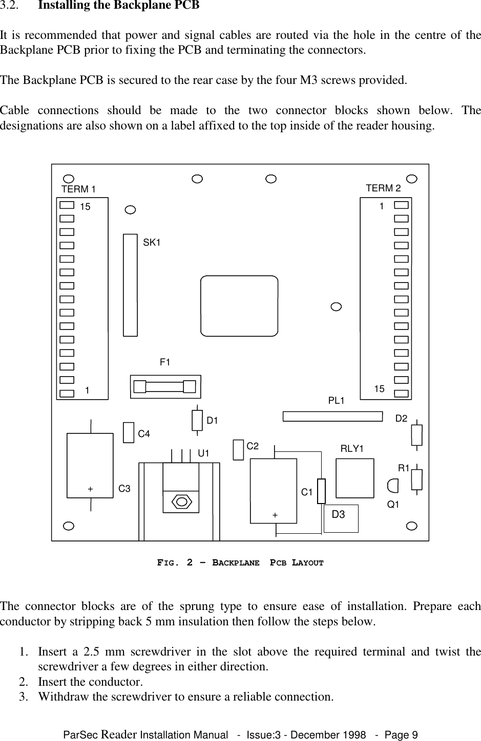
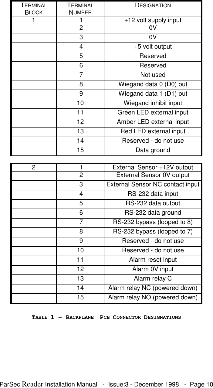
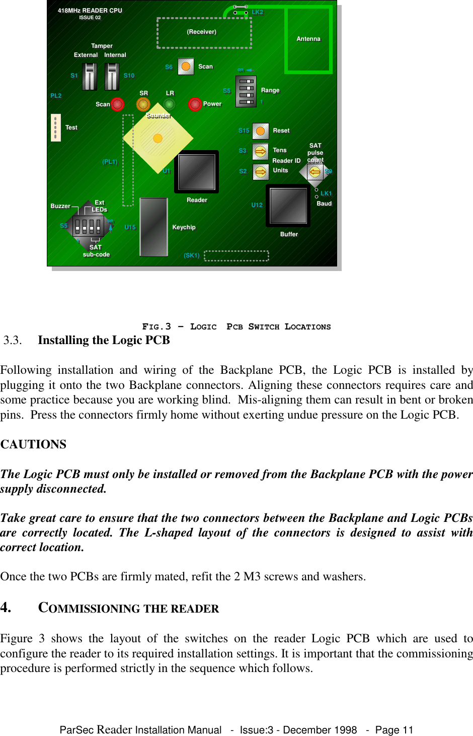
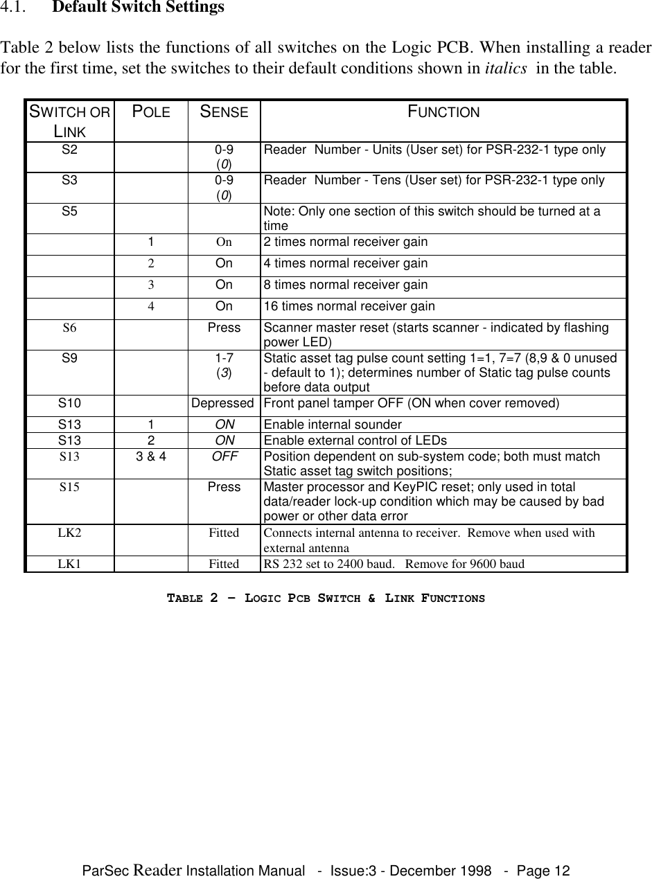
System Installation Manual