Beijing InHand Networks Technology IR9 Industrial Cellular Router User Manual 12 24
Beijing InHand Networks Technology Co., Ltd. Industrial Cellular Router 12 24
UserManual.wiki
>
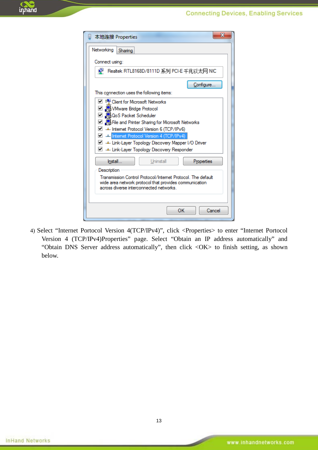
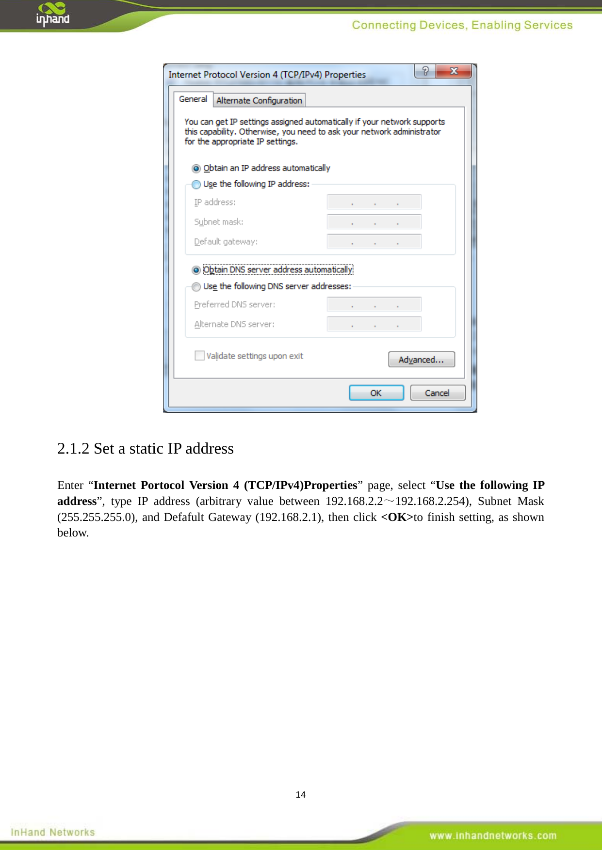
Beijing InHand Networks Technology
>
IR9 User Manual
User Manual 12.24
Navigation menu
Upload a User Manual
Namespaces
Wiki Guide
HTML
PDF
Info
Views
User Manual
Discussion / Help
Navigation
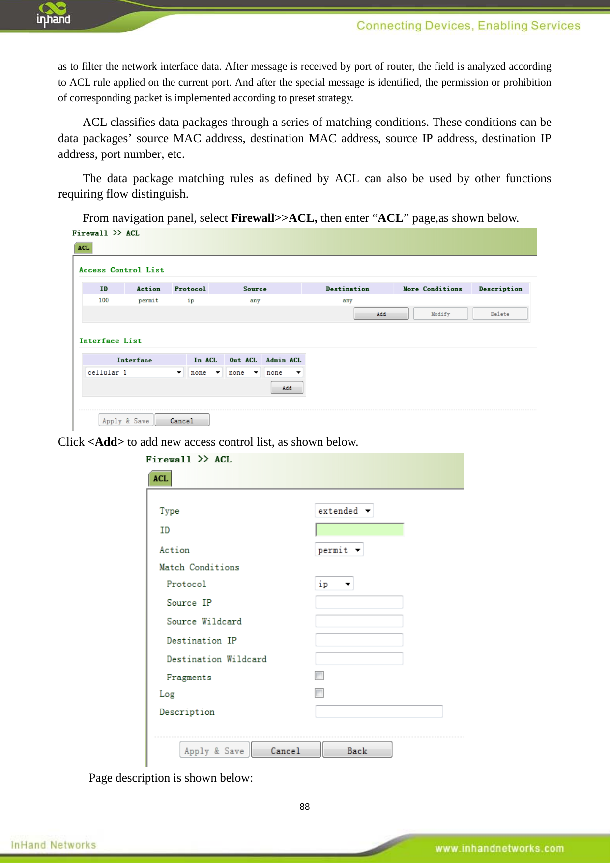
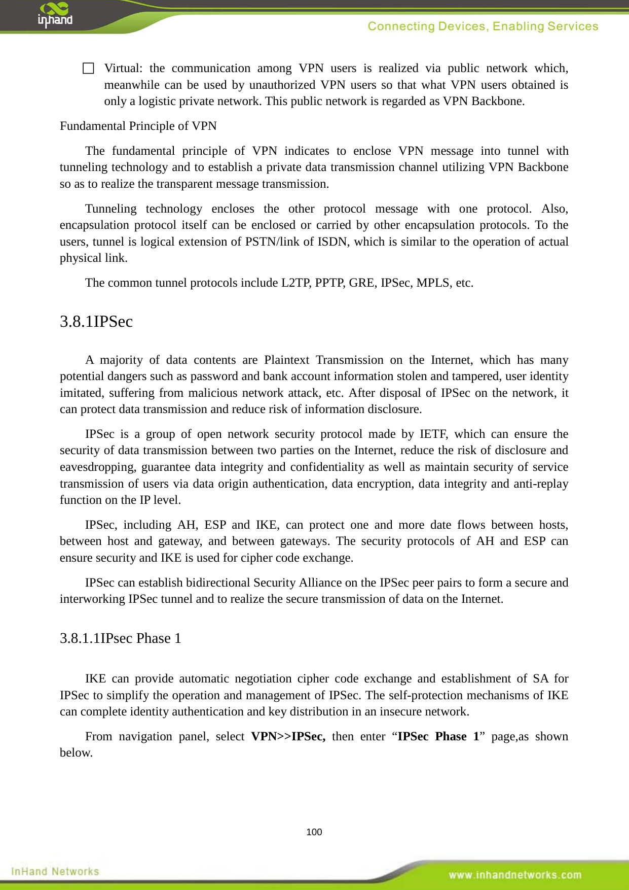
![2 Preface Thanks for choosing InRouter900 series industrial routers! This user’s manual will guide you in detail on how to configure InRouter900. The preface includes the following contents: Readers Conventions in the Manual Obtaining Documentation Technical Support Readers Information Feedback This manual is mainly intended for the following engineers: Network planners On-site technical support and maintenance personnel Network administrators responsible for network configuration and maintenance Conventions in the Manual 1. Format Conventions on Command Line Format Significance Bold Keywords of command line (the part that should be remained unchanged in command and be entered as it is) are expressed with bold font. Italic The parameters of command line (the part that must be replaced with the actual value in command) are expressed in italic. [ ] Indicating that the part in “[]” is optional in command configuration. { x | y | ... } Indicating to select one from multiple options. [ x | y | ... ] Indicating to select one or not to select from multiple options. { x | y | ... } * Indicating to select at least one from multiple options. [ x | y | ... ] * Indicating to select one or more or not to select from multiple options. &<1-n> Indicating that the parameter in front of the symbol & can be repeatedly entered for 1~n times. # The lines starting from no. “#” are comment lines. 2. Format Conventions on Graphic Interface Format Significance](https://usermanual.wiki/Beijing-InHand-Networks-Technology/IR9/User-Guide-2856807-Page-2.png)
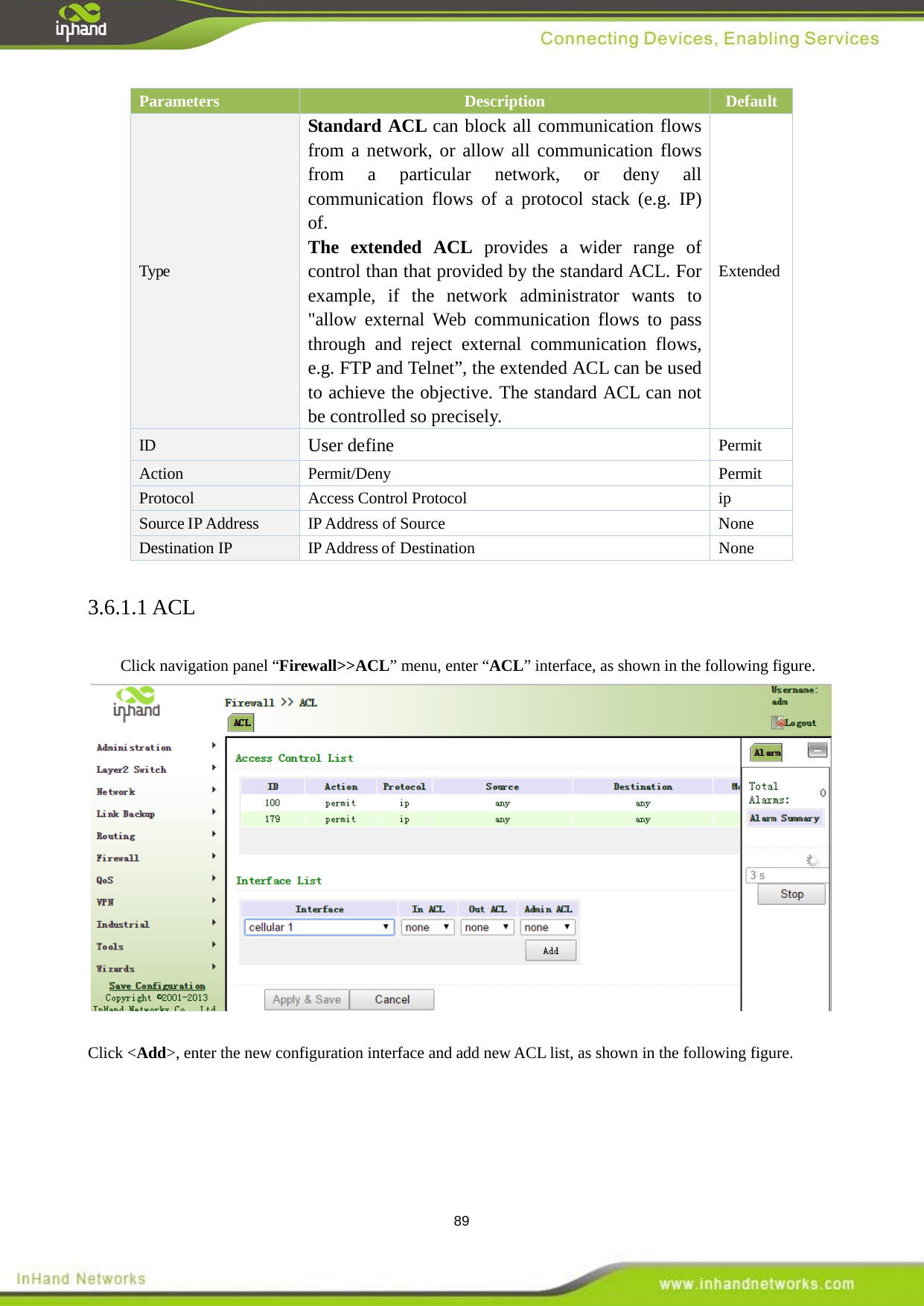
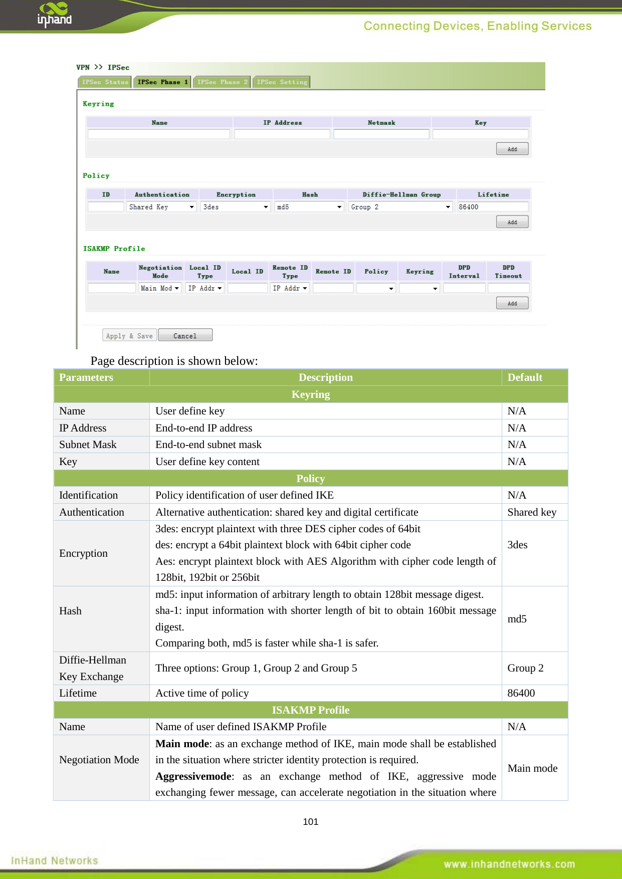
![3 <> The content in angle brackets "<>" indicates button name, e.g. "click <OK> button.” [ ] The content in square brackets "[]" indicates window name, menu name or data sheet, e.g. “pop-up the [New User] window”. / Multi-level menu is separated by "/". For example, the multi-level menu [File / New / Folder] indicates the menu item [Folder] under the submenu [New] under the menu [File]. 3. Various Signs The manual also uses a variety of eye-catching signs to indicate the places to which special attention should be paid in operation. The significances of these signs are as follows: It indicates matters to be noted. Improper operation may cause data loss or damage to the device. The necessary complement or description on the contents of operation. Obtaining Documentation The latest product information is available on the website of InHand (www. inhandnetworks.com): The main columns related to product information on the website of InHand are described as follows: [Service Support / Document Center]: Product information in terms of hardware installation, software upgrade, configuration, etc., is available. [Product Technology]: Documents on product introduction and technology introduction including relevant introduction on product, technical introduction, technical white papers, etc., are available. [Service Support / Software Download]: The supporting information on software version is available. Technical Support E-mail: support@inhandneworks.com Website: www.inhandnetworks.com Information Feedback If you have any question on product information in use, you can feed back through the following ways: E-mail:info@inhandnetworks.com Thanks for your feedback to let us do better!](https://usermanual.wiki/Beijing-InHand-Networks-Technology/IR9/User-Guide-2856807-Page-3.png)


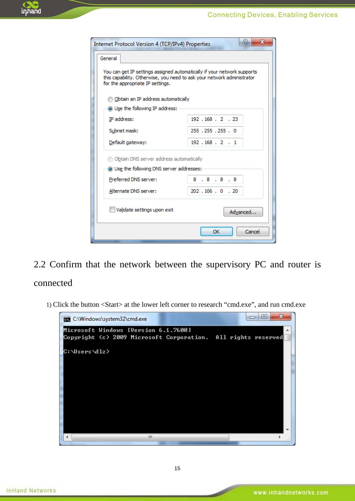
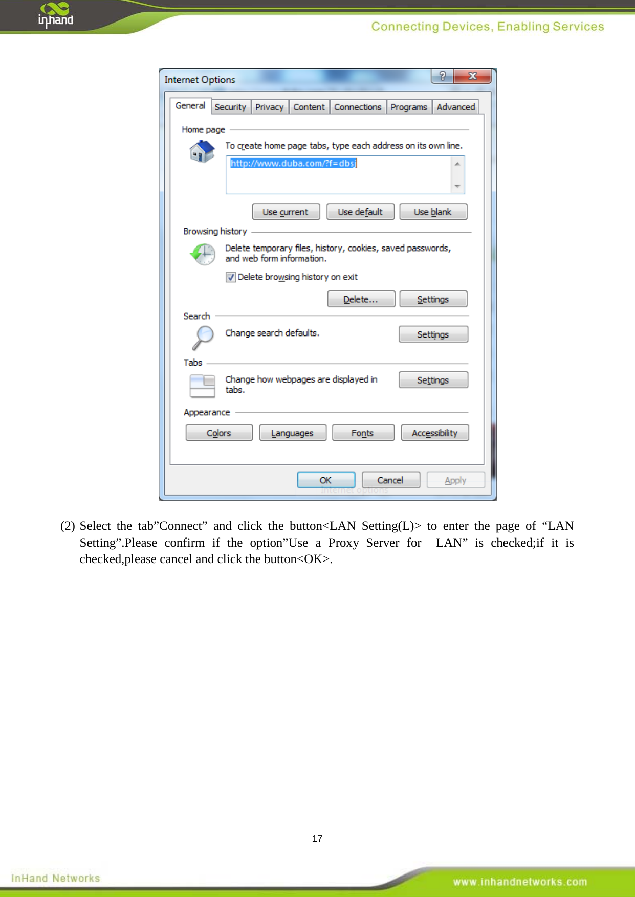
![16 2) Enter "ping 192.168.2.1 (IP address of router; it is the default IP address), and click the button <OK>. If the pop-up dialog box shows the response returned from the router side, it indicates that the network is connected; otherwise, check the network connection. 2.3 Cancel the Proxy Server If the current supervisory computer uses a proxy server to access the Internet, it is required to cancel the proxy service and the operating steps are as follows: (1) Select [Tools/Internet OPtions] in the browser to enter the window of [Internet Options]](https://usermanual.wiki/Beijing-InHand-Networks-Technology/IR9/User-Guide-2856807-Page-16.png)
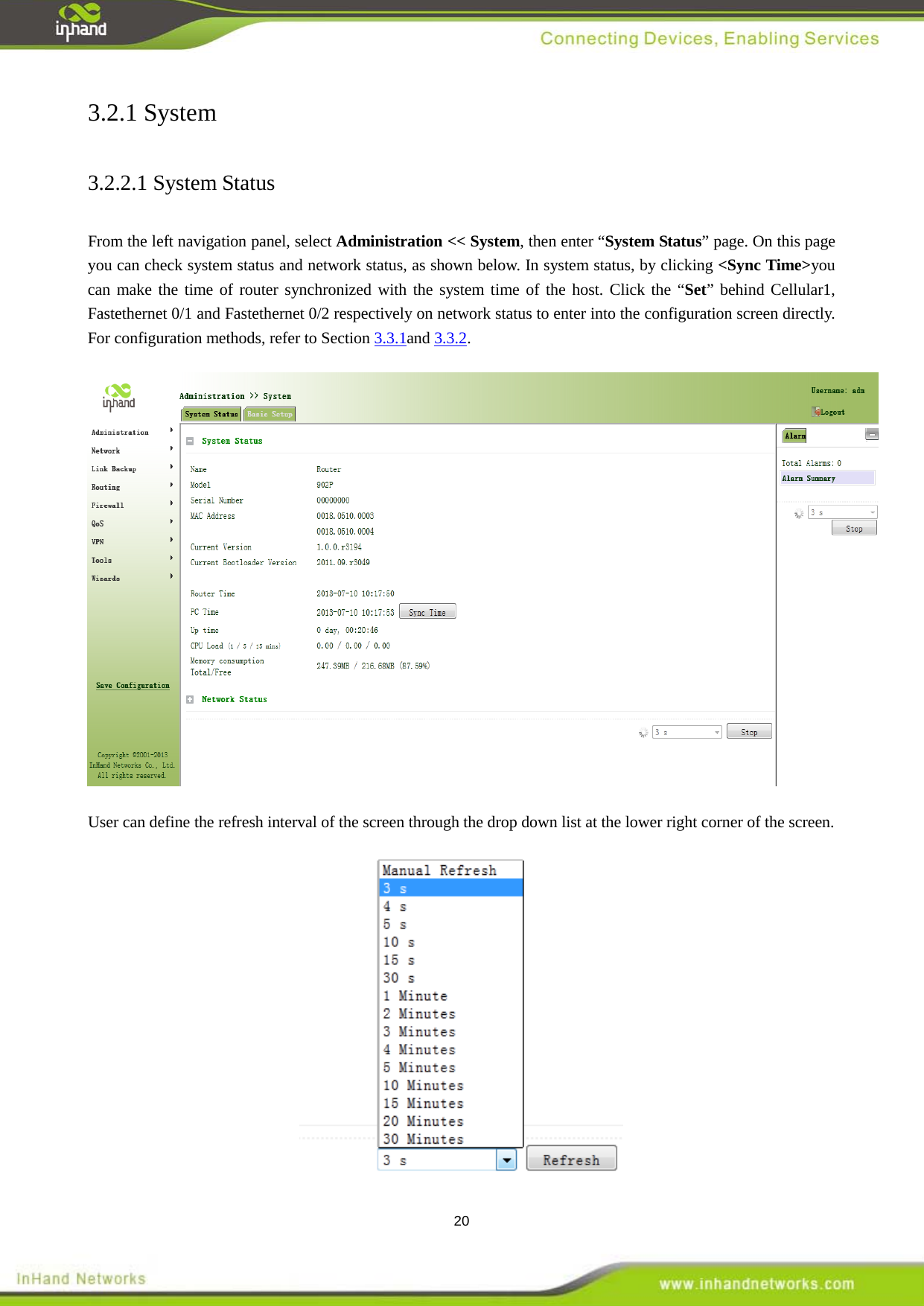
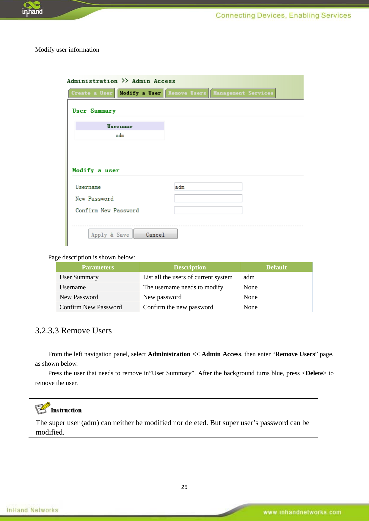
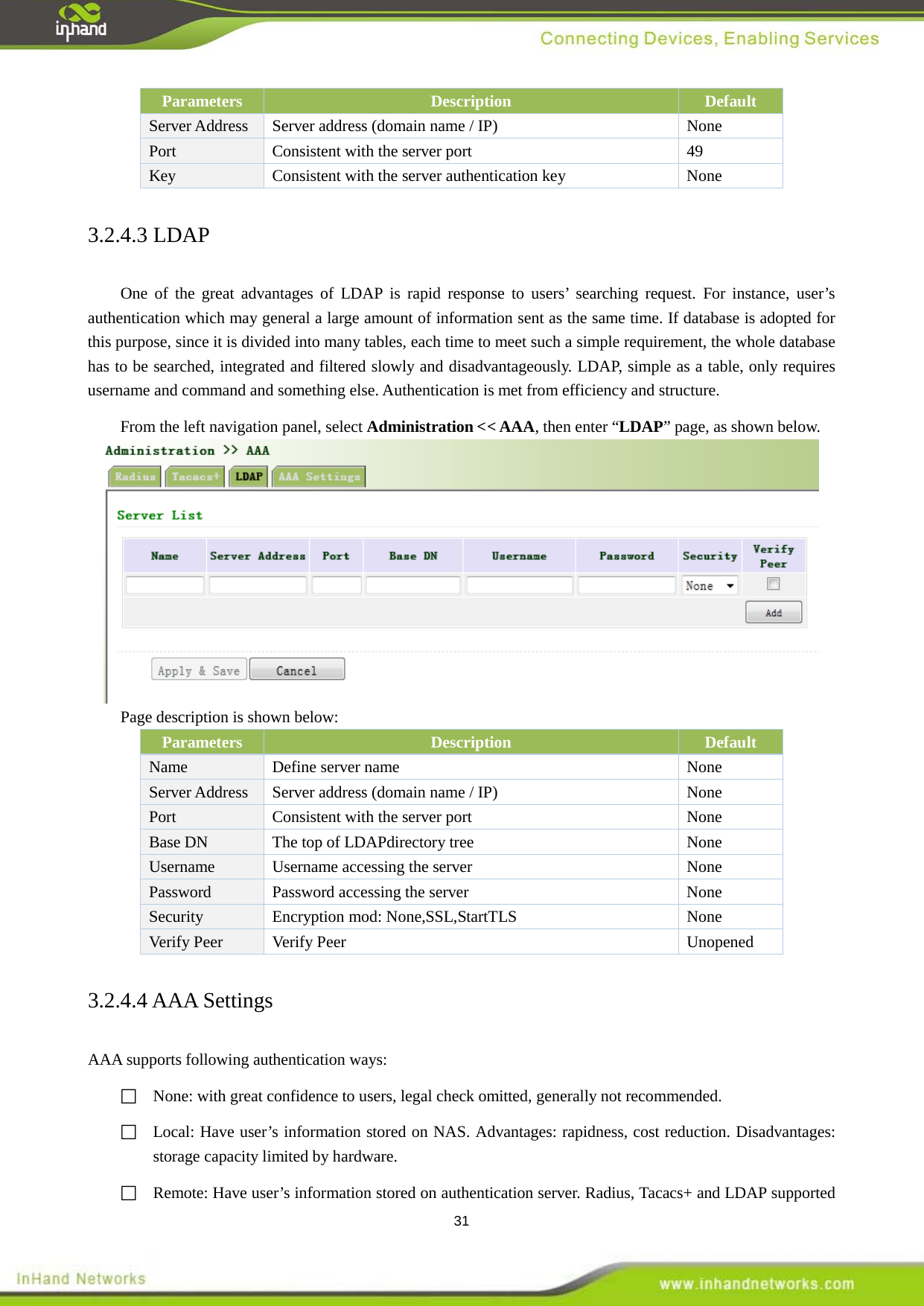
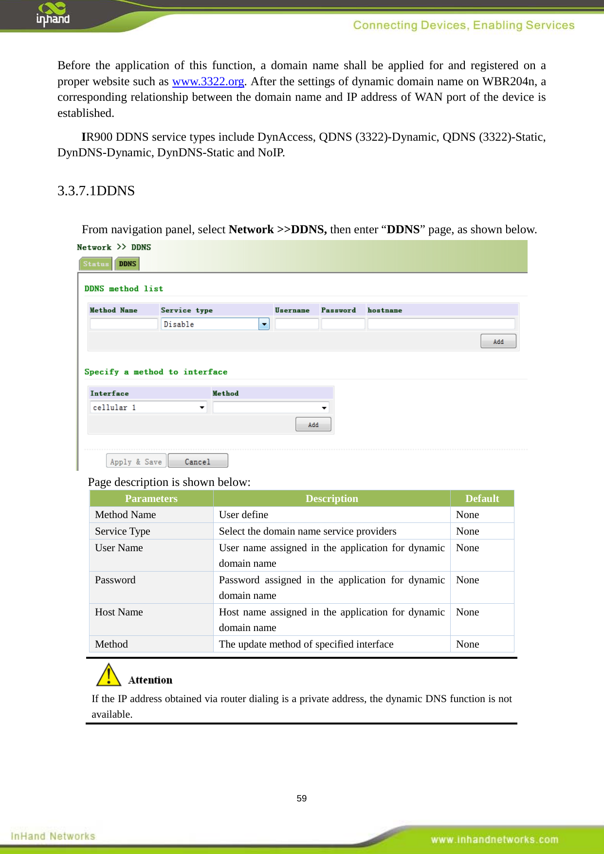
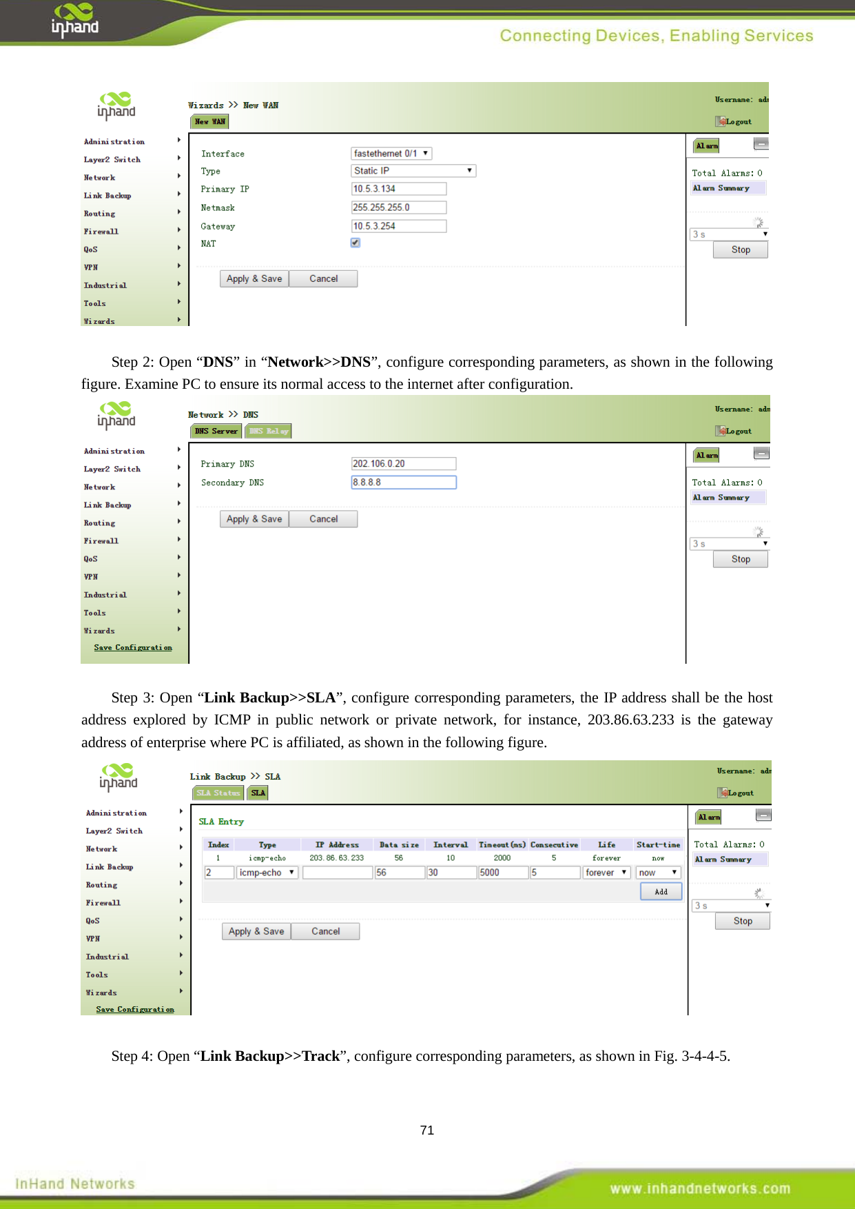
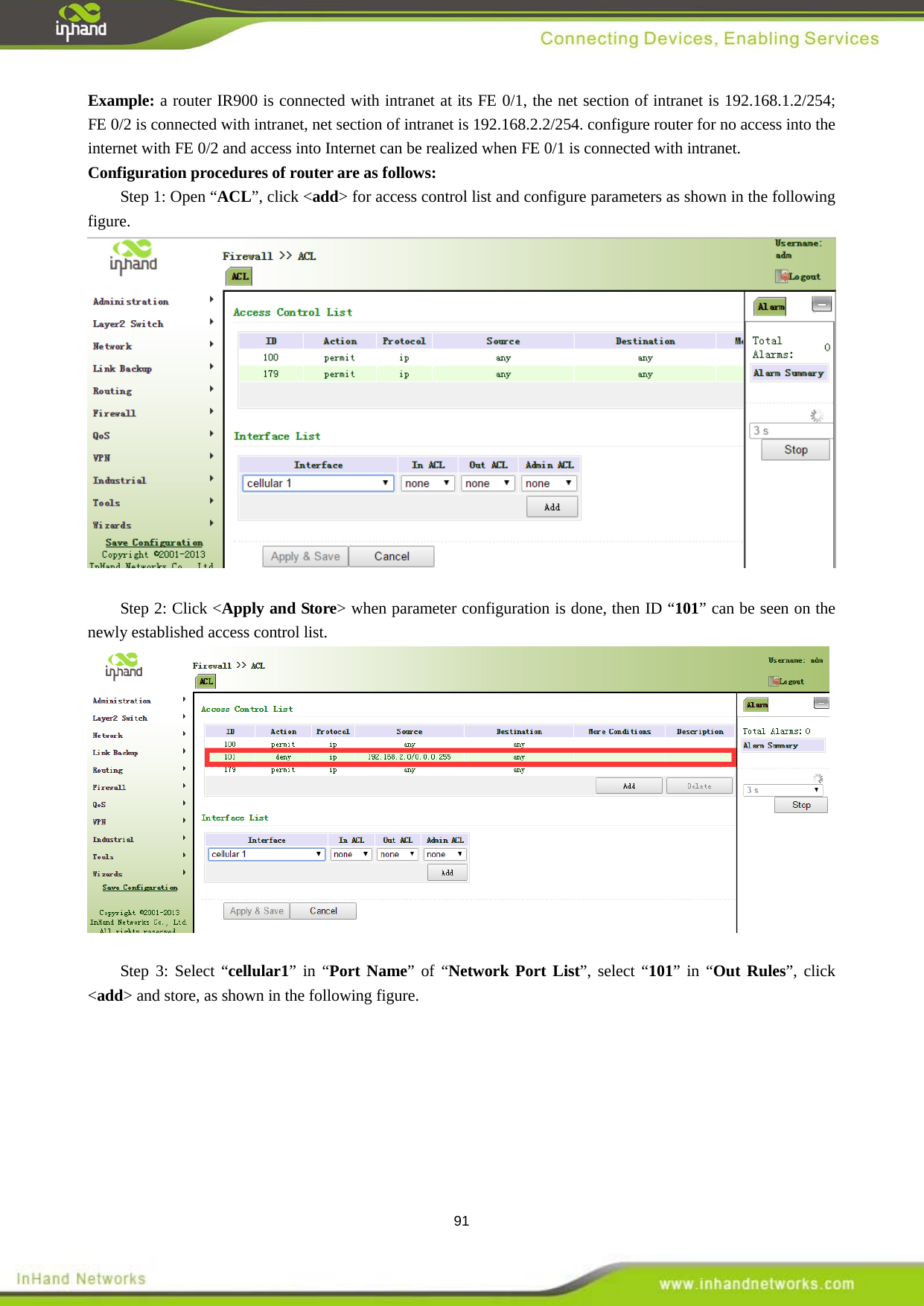
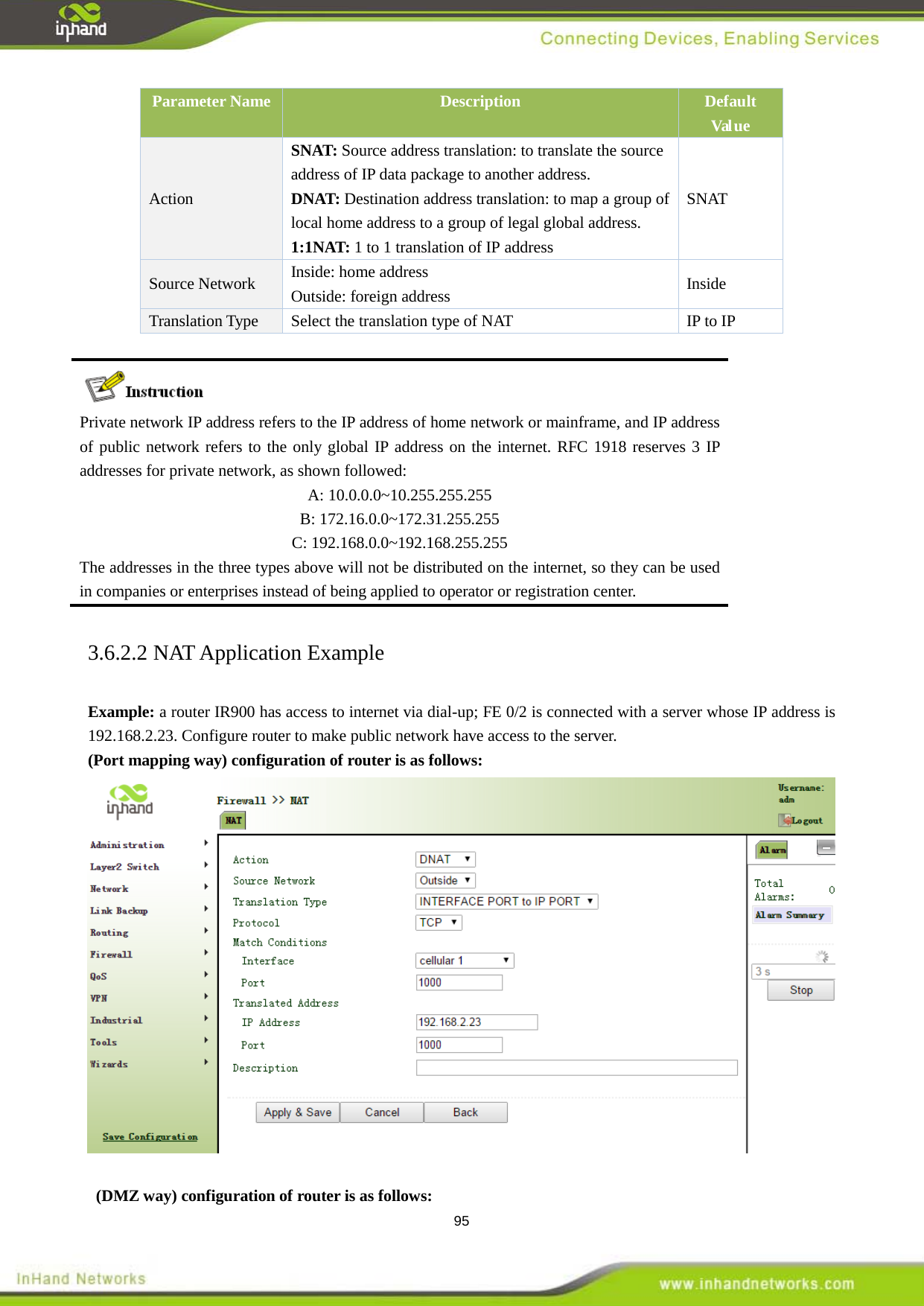
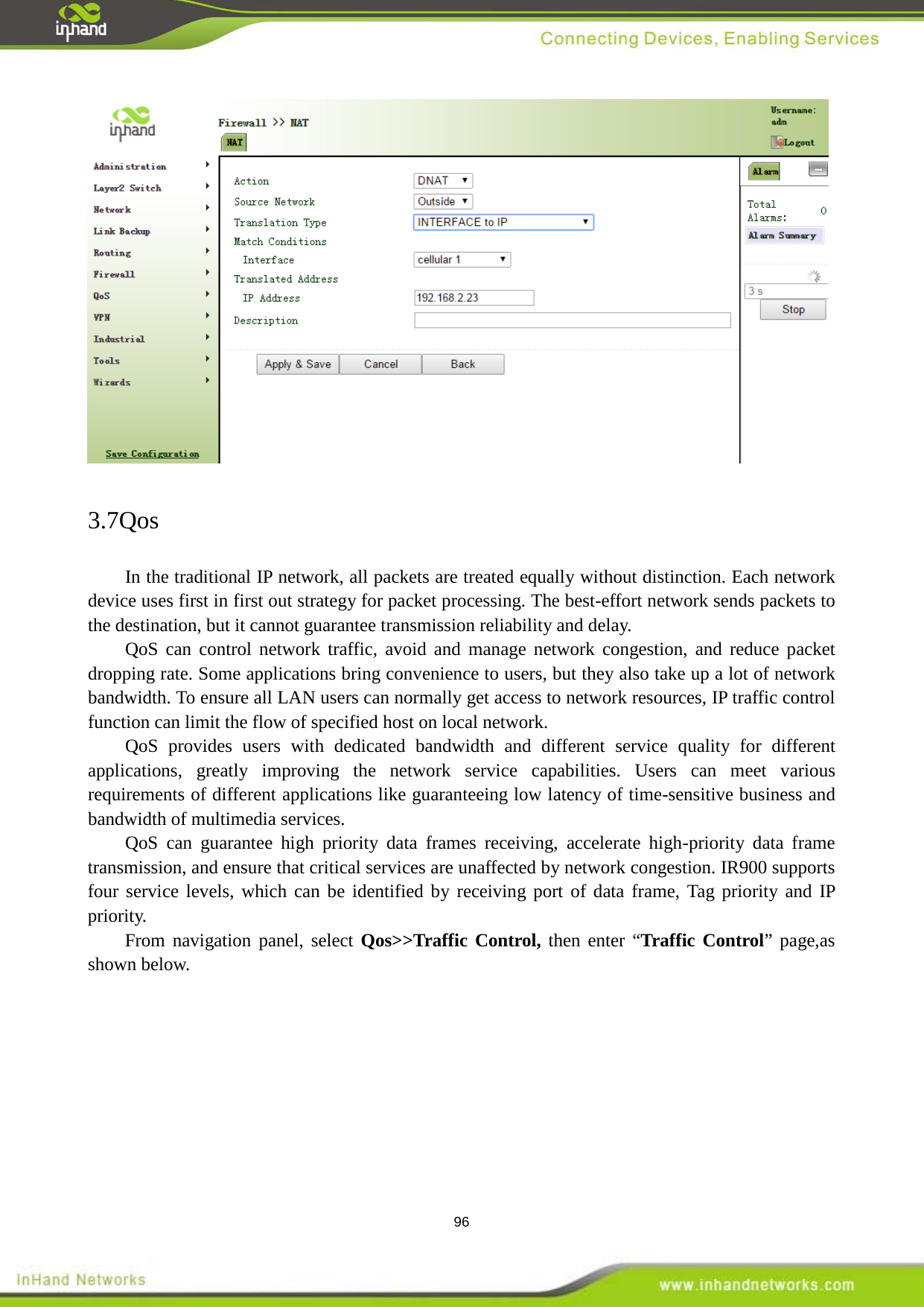
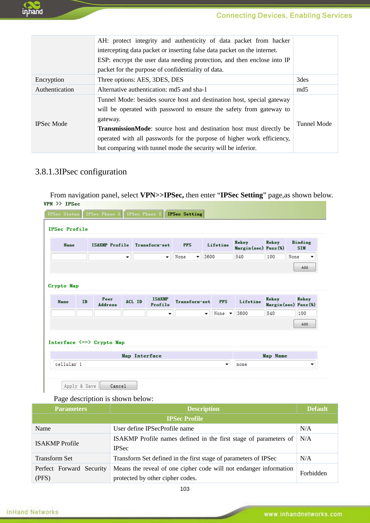
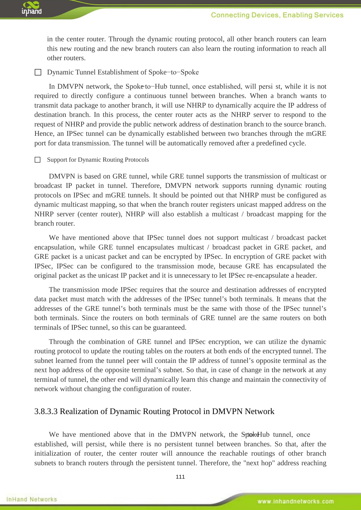
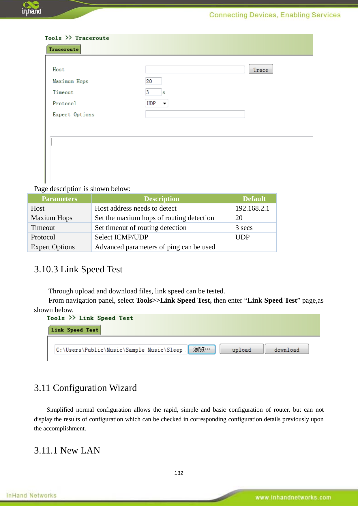
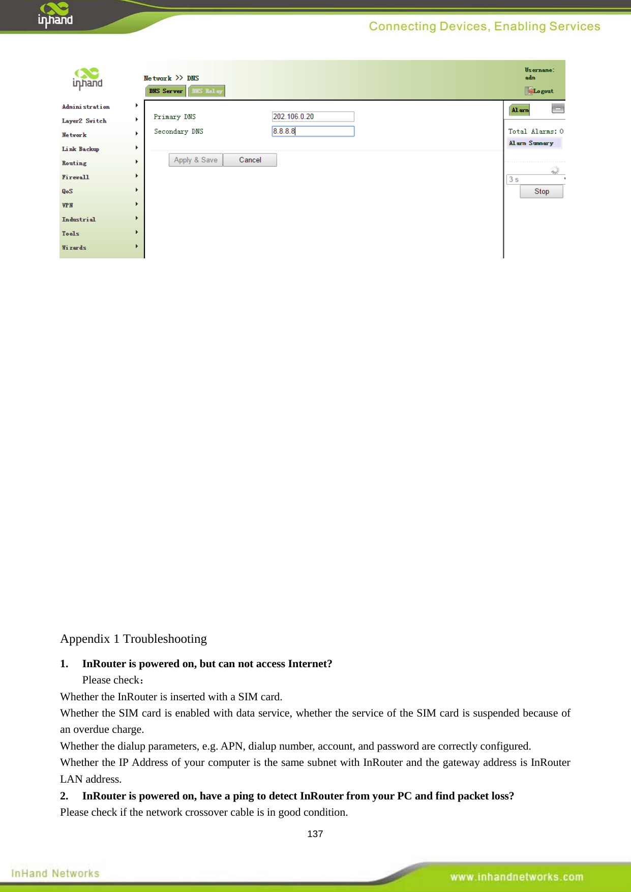
![58 3.3.6.2 DNS Relay DNS forwarding: DNS forwarding is open by default. You can set the specified [Domain Name <=> IP Address] to let IP address match with the domain name, thus allowing access to the appropriate IP through accessing to the domain name. From navigation panel, select Network >>DNS, then enter “DNS Relay” page, as shown below. Page description is shown below: Parameters Description Default Enable DNS Relay On/Off On Host Domain Name N/A IP Address 1 Set IP Address 1 N/A IP Address 2 Set IP Address 2 N/A Once DHCP is turned on, DNS relay will be turned on as default and can’t be turned off; to turn off DNS rely, DHCP Server has to be closed firstly. 3.3.7 Dynamic Domain Name DDNS is the abbreviation of Dynamic Domain Name Server. DDNS maps user's dynamic IP address to a fixed DNS service. When the user connects to the network, the client program will pass the host’s dynamic IP address to the server program on the service provider’s host through information passing. The server program is responsible for providing DNS service and realizing dynamic DNS. It means that DDNS captures user's each change of IP address and matches it with the domain name, so that other Internet users can communicate through the domain name. What end customers have to remember is the domain name assigned by the dynamic domain name registrar, regardless of how it is achieved. DDNS serves as a client tool of DDNS and is required to coordinate with DDNS Server.](https://usermanual.wiki/Beijing-InHand-Networks-Technology/IR9/User-Guide-2856807-Page-58.png)

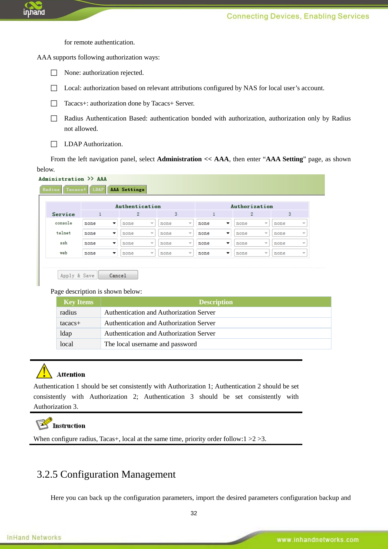
![139 2. Release the button until after the STATUS LED flashes and the ERROR LED is on; 3. After the button is released, the ERROR LED will go off, within 30s press and hold the Restore button again until the ERROR LED flashes; 4. Release the button, the system is now successfully restored to factory default settings. Appendix 2 Instruction of Command Line Help command can be obtained after entering help or “?” into console, “?” can be entered at any time during the process of command input to obtain the current command or help from command parameters, and command or parameters can be automatically complemented in case of only command or command parameter. 1 Help Command 1.1 help [Command] help [<cmd>] [Function] get help from command [View] all views [Parameter]<cmd> command name [Example]](https://usermanual.wiki/Beijing-InHand-Networks-Technology/IR9/User-Guide-2856807-Page-139.png)
![140 enter: help Get the list of all current available command. enter: help show Display all the parameters of show command and using instructions thereof. 2.1 enable 2 View Switchover Command [Command] enable [15 [<password>]] [Function] Switchover to privileged user level. [View] Ordinary user view. [Parameter]15 User right limit level, only supports right limit 15 (super users) at current. <password> Password corresponded to privileged user limit level, hint of password inputting will be given in case of no entering. [Example] Enterenable adm in ordinary user view Switchover to super users and the password 123456 2.2 disable [Command] disable [Function] Exit the privileged user level. [View] Super user view, configure view [Parameter] No [Example] Enter disable in super user view Return to ordinary user view. 2.3 end and ! [Command]end or ! [Function] Exit the current view and return to the last view. [View] Configure view. [Parameter] No [Example] Enter end in configured view Return to super user view. 2.4 exit [Command]exit [Function] Exit the current view and return to the last view (exit console in case that it is ordinary user) [View] all views [Parameter] No [Example] enter exit in configured view Return to super user view. enter exit in ordinary user view Exit console. 3.1 show version 3 Check system state command [Command] show version [Function] Display the type and version of software of router [View] all views [Parameter] No [Example] enter: show version Display the following information:](https://usermanual.wiki/Beijing-InHand-Networks-Technology/IR9/User-Guide-2856807-Page-140.png)
![141 Type : display the current factory type of equipment Serial number : display the current factory serial number of equipment Description : www.inhandnetworks.com Current version : display the current version of equipment Current version of Bootloader: display the current version of equipment 3.2 show system [Command] show system [Function] display the information of router system [View] all views [Parameter] No [Example] enter: show system Display the following information Example: 00:00:38 up 0 min, load average: 0.00, 0.00, 0.00 3.3 show clock [Command] show clock [Function] display the system time of router [View] all views [Parameter] No [Example] enter: show clock Display the following information: For example Sat Jan 1 00:01:28 UTC 2000 3.4 show modem [Command] show modem [Function] Display the MODEM state of router [View] all views [Parameter] No [Example] Enter: show modem Display the following information: Modem type state manufacturer product name signal level register state IMSI number Internet state 3.5 show log [Command] show log [lines <n>] [Function] display the log of router system and display the latest 100 logs in default. [View] all views [Parameter]lines <n> limits the log numbers displayed, wherein, n indicates the latest n logs in case that it is positive integer and indicates the earliest n logs in case that it is negative integer and indicates all the logs in case that it is 0. [Example] enter: show log Display the latest 100 log records. 3.6 show users](https://usermanual.wiki/Beijing-InHand-Networks-Technology/IR9/User-Guide-2856807-Page-141.png)
![142 [Command] show users [Function] display the user list of router. [View] all views [Parameter] No [Example] input: show users Displayed user list of system is as follows: User: ------------------------------------------------- * adm ------ Wherein, user marked with * is super user. 3.7 show startup-config [Command]show startup-config [Function] Display the starting device of router. [View] super user view and configuration view [Parameter] No [Example] enter: show startup-config Display the starting configuration of system. 3.8 show running-config [Command] show running-config [Function] display the operational configuration of router [View] super user view, configuration view [Parameter] No [Example] Enter: show running-config Display the operational configuration of system. 4.1 show interface 4 Check the Command of Internet State [Command] show interface [Function] Display the information of port state of router [View] all views [Parameter] No [Example]enter: show interface Display the state of all ports. 4.2show route [Command] Show ip route [Function] Display the routing list of router [View] all views [Parameter] No [Example] enter: Show ip route Display the routing list of system 4.3 show arp [Command] show arp [Function] Display the ARP list of router [View] all views [Parameter] No](https://usermanual.wiki/Beijing-InHand-Networks-Technology/IR9/User-Guide-2856807-Page-142.png)
![143 [Example] enter: show arp Display the ARP list of system Router has provided ping, telnet and traceroute for internet testing. 5 Internet Testing Command 5.1 ping [Command]ping <hostname> [count <n>] [size <n>] [source <ip>] [Function] apply ICMP testing for appointed mainframe. [View] all views [Parameter]<hostname> tests the address or domain name of mainframe. count <n> testing times size <n> tests the size of data package (byte) source <ip> IP address of appointed testing [Example] enter: ping www.g.cn Test www.g.cn and display the testing results 5.2 telnet [Command] telnet <hostname> [<port>] [source <ip>] [Function] telnet logs in the appointed mainframe [View] all views [Parameter]<hostname> in need of the address or domain name of mainframe logged in. <port>telnet port source <ip> appoints the IP address of telnet logged in. [Example] enter: telnet 192.168.2.2 telnet logs in 192.168.2.2 5.3 traceroute [Command] traceroute <hostname> [maxhops <n>] [timeout <n>] [Function] test the acting routing of appointed mainframe. [View] all views [Parameter]<hostname> tests the address or domain name of mainframe maxhops <n> tests the maximum routing jumps timeout <n> timeout of each jumping testing (sec) [Example] enter: traceroute www.g.cn Apply the routing of www.g.cn and display the testing results. In super user view, router can use configure command to switch it over configure view for management. Some setting command can support no and default, wherein, no indicates the setting of cancelling some parameter and default indicates the recovery of default setting of some parameter. 6 Configuration Command 6.1 configure [Command] configure terminal [Function] switchover to configuration view and input the equipment at the terminal end. [View] super user view [Parameter] No [Example] enter configure terminal in super user view Switchover to configuration view. 6.2 hostname [Command] hostname [<hostname>] default hostname](https://usermanual.wiki/Beijing-InHand-Networks-Technology/IR9/User-Guide-2856807-Page-143.png)
![144 [Function] Display or set the mainframe name of router. [View] Configuration view [Parameter]<hostname> new mainframe name [Example] enter hostname in configuration view Display the mainframe name of router. enter hostname MyRouter in configuration view Set the mainframe name of router MyRouter. enter default hostname in configuration view Recover the mainframe name of router to the factory setting. 6.3 clock timezone [Command] clock timezone <timezone><n> default clock timezone [Function] set the time zone information of router. [View] Configuration view [Parameter]<timezone> timezone name, 3 capitalized English letters <n> time zone deviation value, -12~+12 [Example] enter clock timezone CST -8 in configuration view The time zone of router set is east eighth area and the name is CST (China’s standard time). enter default clock timezone in configuration view The time zone of recovered router is at the factory setting. [Command]clock set <YEAR/MONTH/DAY> [<HH:MM:SS>] 6.4 clock set [Function] set the date and time of router. [View] Configuration view [Parameter]<YEAR/MONTH/DAY> date, format: Y-M-D <HH:MM:SS > time, format: H-M-S [Example] enter clock set 2009-10-5 10:01:02 in configuration view The time of router set is 10:01:02 of Oct. 5th6.5 ntp server , 2009 morning. [Command]ntp server <hostname> no ntp server default ntp server [Function] set the customer end of internet time server [View] configuration view [Parameter]<hostname> address or domain name of mainframe of time server [Example] enter sntp-client server pool.ntp.org in configuration view Set the address of internet time server pool.ntp.org. 7.1 reboot 7 System Management Command [Command] reboot [Function] System restarts. [View] super user view, configuration view [Parameter] No [Example] enter reboot in super user view](https://usermanual.wiki/Beijing-InHand-Networks-Technology/IR9/User-Guide-2856807-Page-144.png)
![145 System restarts. 7.2enable password [Command] enable password [<password>] [Function] modify the password of super user. [View] configuration view [Parameter]<password> new super user password [Example] enter enable password in configuration view Enter password according to the hint. 7.3username [Command] username <name> [password [<password>]] no username <name> default username [Function] set user name, password [View] configuration view [Parameter] No [Example] enter username abc password 123 in configuration view Add an ordinary user, the name is abc and the password is 123. enter no username abc in configuration view Delete the ordinary user with the name of abc. enter default username in configuration view. Delete all the ordinary users. Appendix 3 Glossary of Terms Abbreviation Full English Name Meaning 100Base-TX 100Base-TX 100Mbit / s baseband Ethernet specification uses two pairs of category 5 twisted-pair connection, which can provide the maximum transmission rate of 100Mbit / s 10Base-T 10Base-T 10Mbit / s baseband Ethernet specification uses two pairs of twisted-pair (category 3/4/5 twisted pair) connection, one of which will be used for sending data and the other for receiving data, which can provide the maximum transmission rate of 10Mbit / s DDNS Dynamic Domain Name Dynamic Domain Name Service can achieve the resultion between the fixed domain name and the dynamic IP address](https://usermanual.wiki/Beijing-InHand-Networks-Technology/IR9/User-Guide-2856807-Page-145.png)