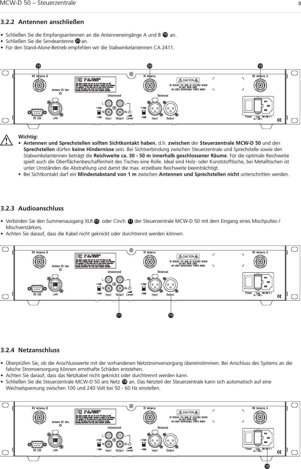
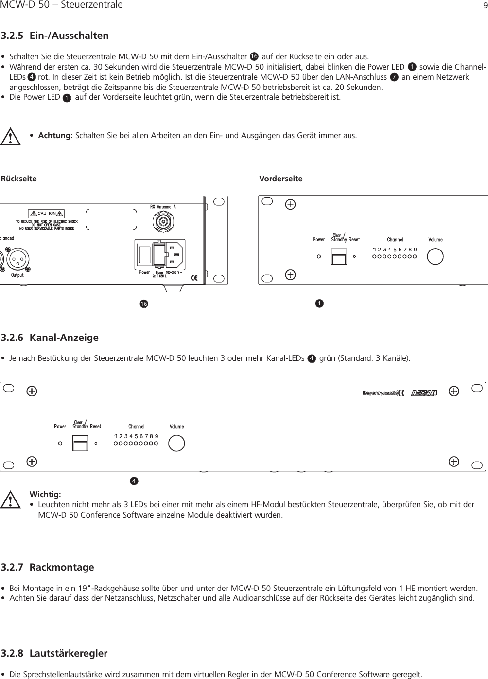
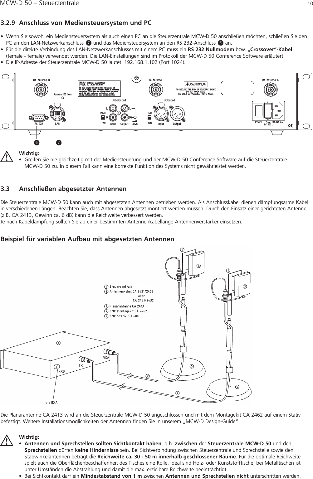
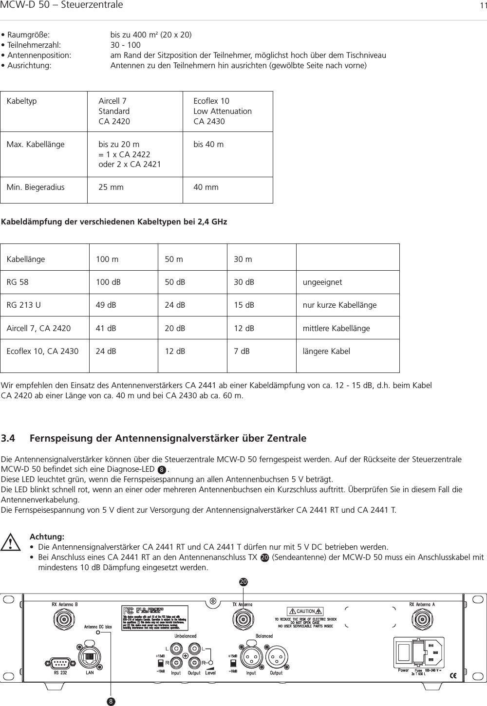
Beyerdynamic MCWD53X Wireless Microphone Unit User Manual MCWD 50 BA DEF 1108
Beyerdynamic Wireless Microphone Unit MCWD 50 BA DEF 1108
UserManual.wiki
>
Beyerdynamic
>
MCWD53X User Manual
User Manual
Navigation menu
Upload a User Manual
Namespaces
Wiki Guide
HTML
PDF
Info
Views
User Manual
Discussion / Help
Navigation
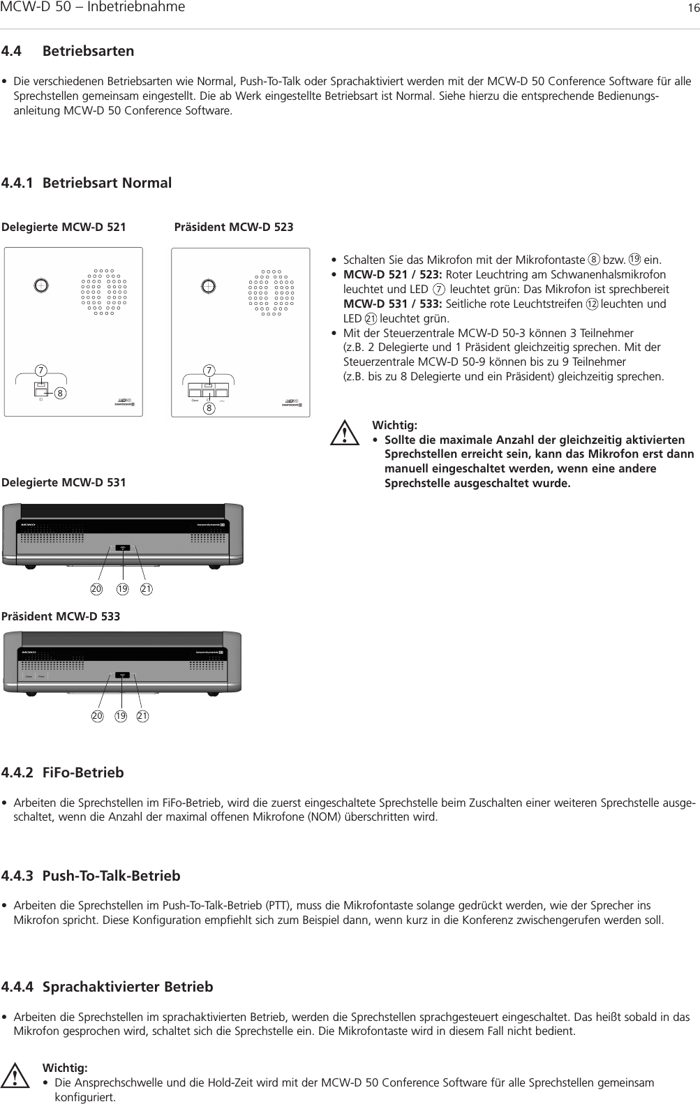
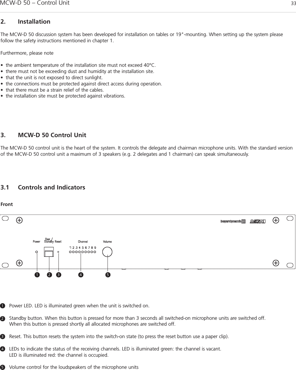
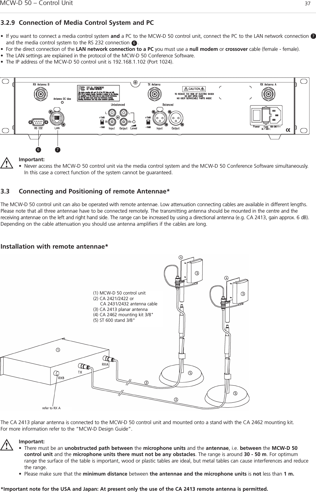
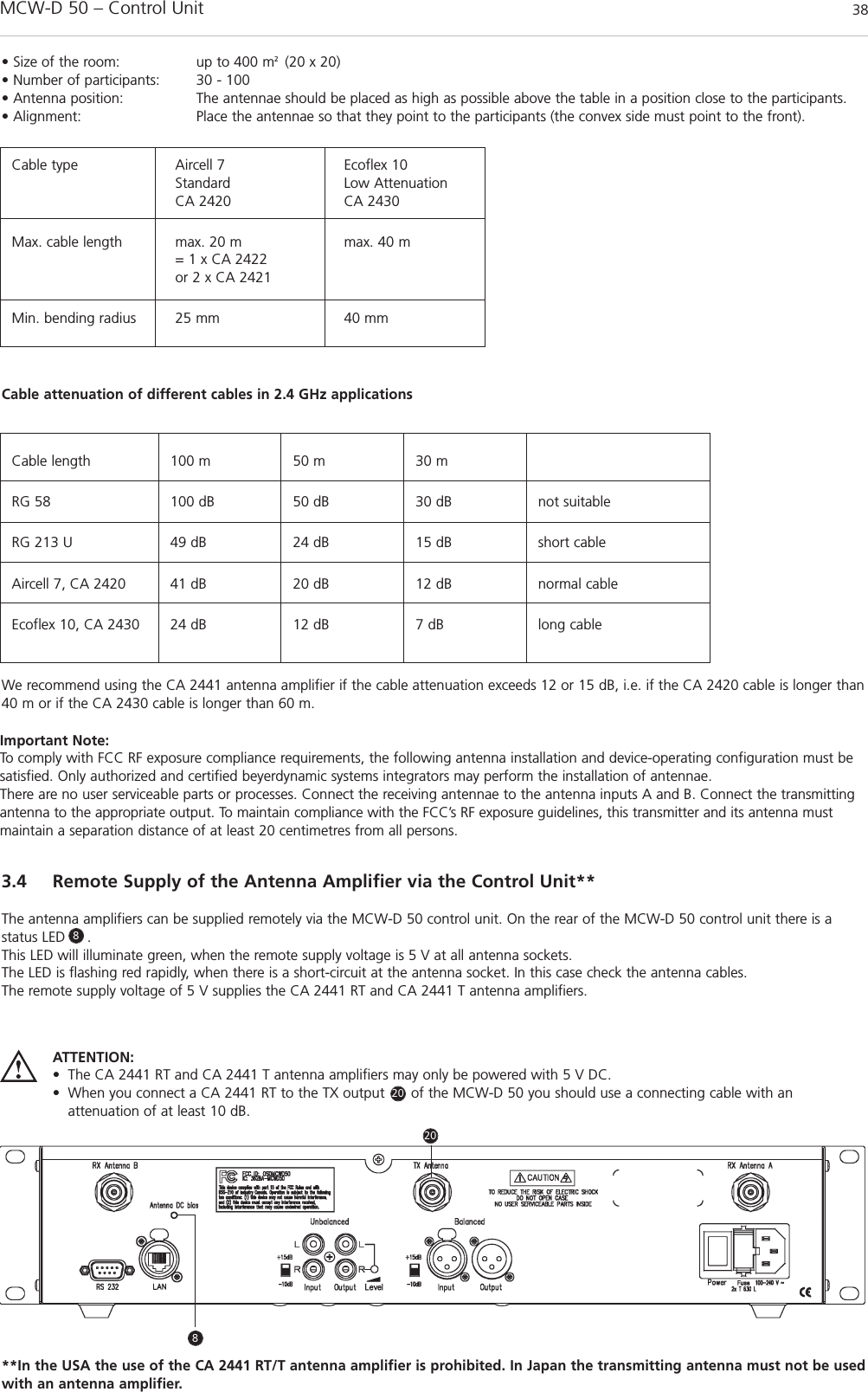
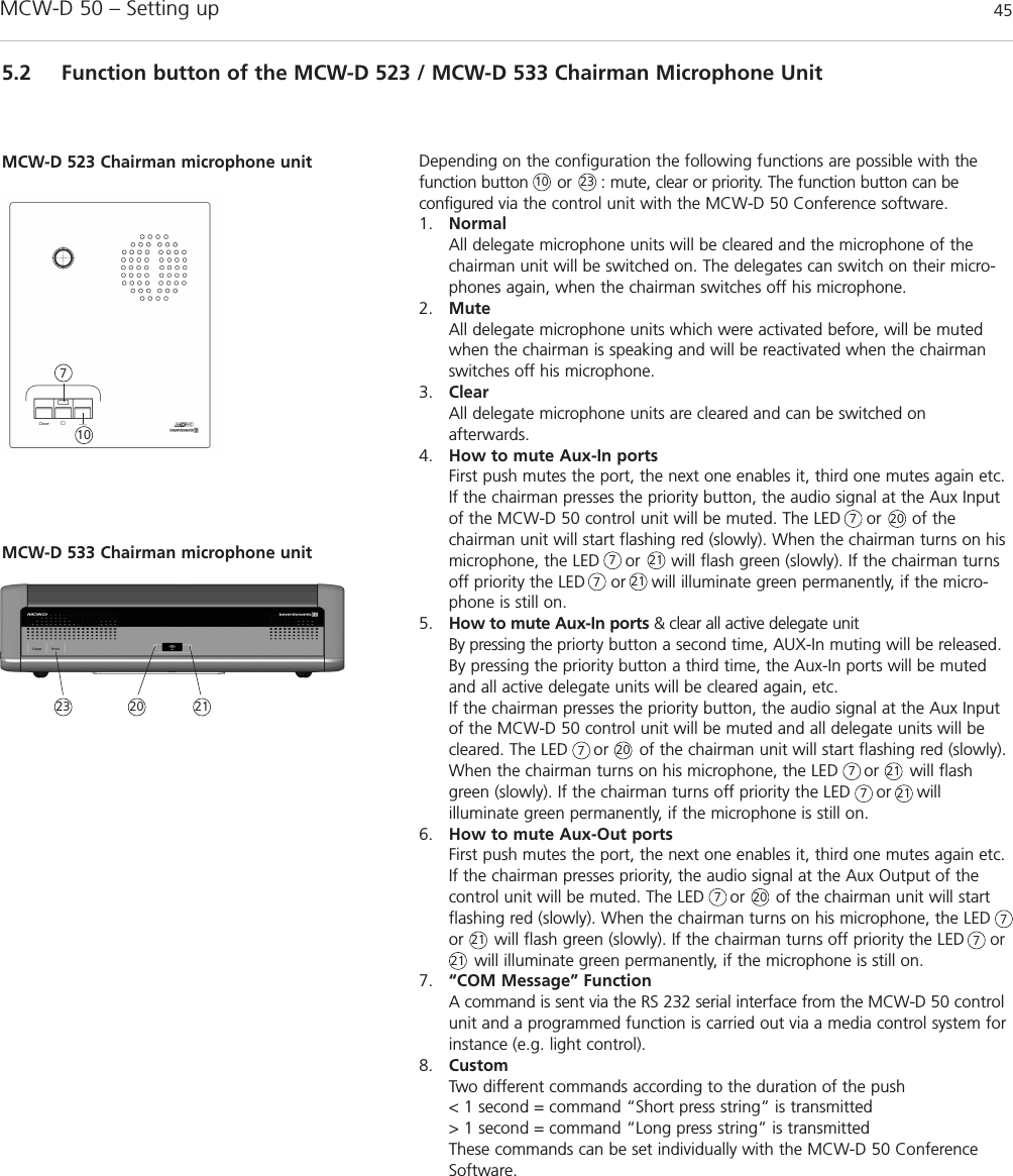
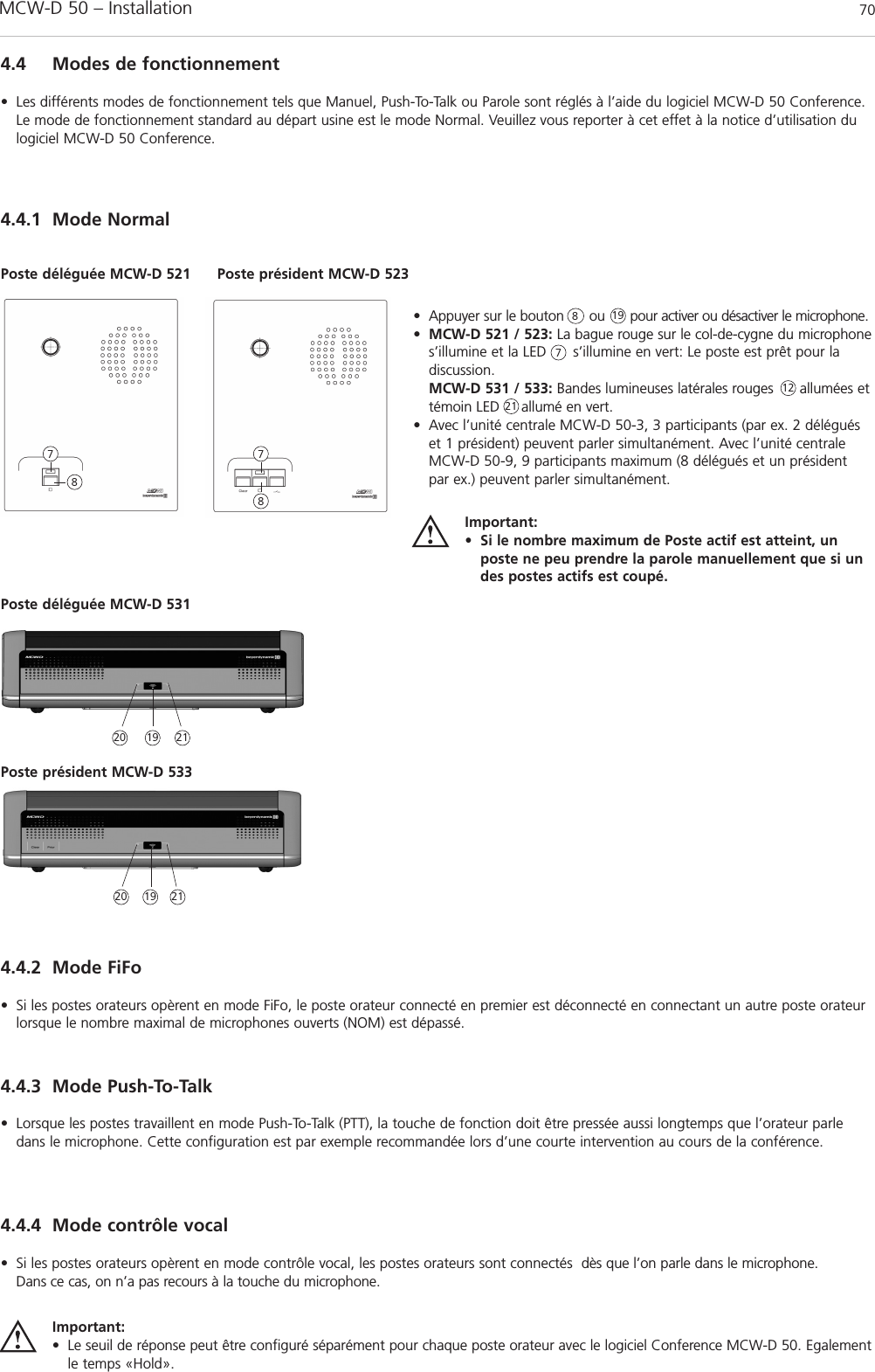
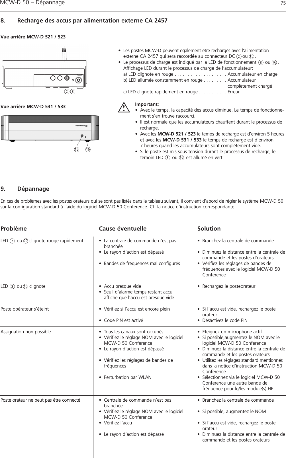
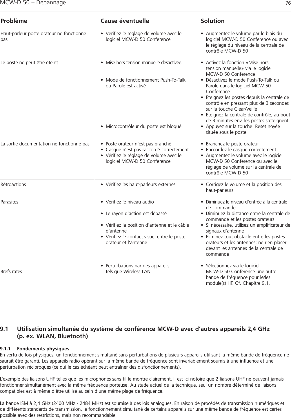
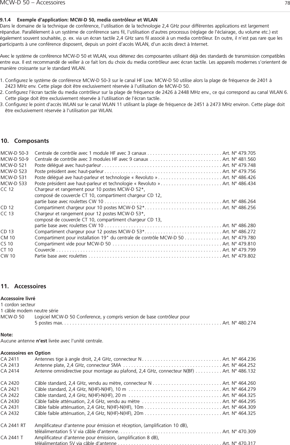
![MCW-D 50 – Important Safety Instructions 32Special Note about Power Cables for Canada and the USACanadaOnly use a power cable according to CSA C22.2 No.21 and CSA C22.2 No. 42.USAThe earthing conductor in a supply cord, or in an interconnecting cable shall have an equivalent or larger cross-sectional area that the current-carrying conductors in the supply cord or cable. With reference to earthing conductors, the insulation colour may be green orgreen/yellow.Mains Supply flexible cords shall comply with UL 817, be marked VW-1, and have an ampacity not less than the current drawn by theapparatus.Table of cable types / cable lengths being used in the USAApparatus type Cord type Cord length, m bPortable, table-top, floor standing and NISPT-2a, SPT-2, SV, SVT, SVE, SJ, SJT, SJE 1.5 minimumrack-mounted audio and video apparatusHousehold musical instruments NISPT-2a, SPT-2, SV, SVT, SVE 3.0 maximumSJ, SJT, SJE 7.5 maximumCoffee table cSV, SVT, SVE, SJ, SJT, SJE 3.0 minimumUndercabinet and portable apparatus with NISPT-2a, SPT-2 1.5 minimumcord storage compartmentCommercial amplifier-speakers, musical SJ, SJT, SJE 7.5 maximuminstruments and sound systems da Appliance wiring material construction that has been determined to be equivalent is acceptable.b The length of a flexible cord on an apparatus intended for a special installation is not prohibited from being less than specified.c A coffee-table type apparatus is a type that is finished on all four sides and intended for use in the centre of the room.d A system comprised of a number of different components found for example in a school system or language teaching system.Control UnitFCC ID: OSDMCWD50Canada: IC: 3628A-MCWD50Microphone UnitsFCC ID: OSDMCWD5xxCanada: IC: 3628A-MCWD5xxNOTICE:This device complies with Part 15 of the FCC Rules [and with RSS-210 of Industry Canada].Operation is subject to the following two conditions:(1) this device may not cause harmful interference, and (2) this device must accept any interference received, including interference that may cause undesired operation.NOTICE:Changes or modifications made to this equipment not expressly approved by (manufacturer name) may void the FCC authorization to operate this equipment.NOTE: This equipment has been tested and found to comply with the limits for a Class B digital device, pursuant to Part 15 of the FCCRules. These limits are designed to provide reasonable protection against harmful interference in a residential installation. This equipmentgenerates, uses and can radiate radio frequency energy and, if not installed and used in accordance with the instructions, may cause harmful interference to radio communications. However, there is no guarantee that interference will not occur in a particular installation. If this equipment does cause harmful interference to radio or television reception, which can be determined by turning the equipment offand on, the user is encouraged to try to correct the interference by one or more of the following measures:• Reorient or relocate the receiving antenna.• Increase the separation between the equipment and receiver.• Connect the equipment into an outlet on a circuit different from that to which the receiver is connected.• Consult the dealer or an experienced radio/TV technician for help.](https://usermanual.wiki/Beyerdynamic/MCWD53X/User-Guide-1078105-Page-32.png)