Bioness Neuromodulation A Bioness STRT-RC-V00 Remote control unit User Manual
Bioness Neuromodulation ltd. A Bioness Inc Company Remote control unit
Manual
User Manual
StimRouter™ Implantable
Neurostimulator
Bioness Inc.
Rx Only
CAUTION:
United States federal law restricts this device
to sale by or on the order of a physician.

Copyright
©2009 by Bioness Inc. All Rights Reserved. No part of this publication may be
reproduced, transmitted, transcribed, stored in a retrieval system or translated into any
language or any computer language, in any form or by any third party, without the prior
written permission of Bioness Inc.
Guarantees
Bioness Inc. reserves the right to modify, without prior notice, information relating to its
products to improve their reliability or operating capacity.
Disclaimer
Bioness Inc. shall not be liable for any injury or damage suffered by any person, either
directly or indirectly, as a result of the unauthorized use or repair of Bioness Inc.
products. Bioness does not accept any responsibility for any damage caused to its
products, either directly or indirectly, as a result of use and/or repair by unauthorized
personnel.
Enironmental Policy
Service personnel are advised that when changing any part of the StimRouter, care
should be taken to dispose of those parts in the correct manner; where applicable, parts
should be recycled. When the life cycle of the StimRouter has been completed, the
product should be discarded according to the laws and regulations of the local authority.
Registered Trademarks
StimRouter™, Bioness®, the Bioness Logo and LiveOn™ are trademarks of Bioness
Inc. | www.bioness.com
Use of the symbols ® and ™ herein refers to the registration status of trademarks in the
U.S. only. These trademarks may also be registered in other countries.
Manufacturer: Bioness Inc.
25103 Rye Canyon Loop
Valencia, CA 91355
19 Ha’Haroshet Street
PO Box 2500
Industrial Zone
Ra’Anana 43654, Israel
Bioness Customer Support:
Telephone: (800) 211-9136
Fax: (661) 362-4851
email: info@bioness.com
www.bioness.com
List of Symbols
Conformity Certification
The StimRouter complies with Part 15 of the FCC Rules. Operation is subject to
the following two conditions:
1This device may not cause harmful interference, and
2This device must accept any interference received, including interference
that may cause undesired operation.
Symbols Definition
Type BF Applied Part
Electronic Testing Lab, indicates product meets
U.S. and Canadian product safety standards.
This device complies with UL 60601-1 and CSA
C22.2 No. 601-1-M90.
Non-Ionizing Radiation
Class II Equipment
Manufacturer
Date of Manufacture
Warning
1. Introduction 1
Your StimRouter User Kit . . . . . . . . . . . 1
Your Programming Session . . . . . . . . . . 1
User Registration Information . . . . . . . . . 2
Your Medical Device ID Card . . . . . . . . . 2
Bioness Customer Support . . . . . . . . . . 2
2. General Warnings and Cautions 3
Indications for Use . . . . . . . . . . . . . . . 3
Contraindications . . . . . . . . . . . . . . . . 3
Warnings . . . . . . . . . . . . . . . . . . . . . 4
Diathermy. . . . . . . . . . . . . . . 4
Magnetic Resonance Imaging (MRI) . 4
Implanted Stimulation Devices . . . . 4
Flammable Fuel or Chemicals . . . . 5
Electrosurgery Devices . . . . . . . . 5
High-Frequency Surgical Equipment . 5
Driving and Operating Machinery. . . 5
Pregnancy . . . . . . . . . . . . . . 5
Long-Term Effectiveness of
Neurostimulation . . . . . . . . . . . 5
System Programming. . . . . . . . . 6
System Components . . . . . . . . . 6
Precautions. . . . . . . . . . . . . . . . . . . . 6
Medical Devices/Therapies . . . . . . 6
For Patient Use Only . . . . . . . . . 6
Postural Changes. . . . . . . . . . . 6
Keep out of Reach of Children . . . . 7
Skin Abnormalities . . . . . . . . . . 7
Skin Irritation . . . . . . . . . . . . . 7
User Patch Placement and Stimulation 7
X-Ray Examinations . . . . . . . . . 8
Known or Suspected Heart Problems 8
Device Failure . . . . . . . . . . . . 8
Care and Handling of Components. . 8
Storage and Operation Temperatures 8
Expiration Date. . . . . . . . . . . . . 8
Adverse Effects . . . . . . . . . . . . . . . . . 8
Risks Related to Stimulation . . . . . . 9
Risks Related to the Device . . . . . . 9
3. User Kit Contents 11
4. Device Description 13
Implantable Lead . . . . . . . . . . . . . . . 14
Stimulation End . . . . . . . . . . . 14
Pick-Up End . . . . . . . . . . . . . 14
User Patch . . . . . . . . . . . . . . . . . . . 14
Design Features . . . . . . . . . . . 14
Two Surface Gel Electrodes. . . . 14
Integrated Battery . . . . . . . . . 14
External Pulse Transmitter Cradle 14
EPT Latching Mechanism . . . . . 14
Accessories . . . . . . . . . . . . . 15
User Patch Carrying Case . . . . 15
Patch Sleeves . . . . . . . . . . . 15
External Pulse Transmitter. . . . . . . . . . 15
Remote Control . . . . . . . . . . . . . . . . 15
Operating Modes . . . . . . . . . . . 15
Standby . . . . . . . . . . . . . . 15
Program . . . . . . . . . . . . . . 16
Stimulation. . . . . . . . . . . . . 16
Operating Buttons . . . . . . . . . . 16
On/Off . . . . . . . . . . . . . . . 16
Mode . . . . . . . . . . . . . . . 16
Plus/Minus. . . . . . . . . . . . . 16
Volume . . . . . . . . . . . . . . 17
On/Off Indicator Lights . . . . . . . . 17
Remote Control . . . . . . . . . . 17
Stimulation. . . . . . . . . . . . . 17
Program . . . . . . . . . . . . . . 17
Table of Contents
Digital Display. . . . . . . . . . . . . 17
Intensity . . . . . . . . . . . . . . 17
Program . . . . . . . . . . . . . . 17
Battery Charging . . . . . . . . . . 17
Battery Fully Charged . . . . . . . 17
Radio Frequency Registration Error .
18
Radio Frequency Registration
Complete. . . . . . . . . . . . . . 18
Radio Frequency Registration in
Progress . . . . . . . . . . . . . . 18
LEDs . . . . . . . . . . . . . . . . . 18
User Patch Icon . . . . . . . . . . 18
Radio Frequency (RF) Icon . . . . 18
Remote Control Icon . . . . . . . . 19
Visual Alerts . . . . . . . . . . . . . 19
Low Battery, Remote Control . . . 19
Low Battery, User Patch . . . . . . 19
Faulty Electrode Contact. . . . . . 19
Radio Frequency Failure. . . . . . 19
Component Malfunction . . . . . . 19
Audio Alerts. . . . . . . . . . . . . . 19
Beep . . . . . . . . . . . . . . . . 19
Battery Compartment . . . . . . . . . 20
Accessories . . . . . . . . . . . . . . 20
Remote Control Charger. . . . . . 20
Remote Control Neck Strap . . . . 20
Remote Control Wrist Strap . . . . 20
Remote Control Pouch. . . . . . . 20
5. Technical Specifications 21
6. Environmental Conditions that
Affect Use 25
Storage and Handling. . . . . . . . . . . . . 25
Radio Communication Information. . . . . 25
Security Screening Devices . . . . . . . . . 26
Cell Phones. . . . . . . . . . . . . . . . . . . 26
7. Set-Up Instructions 27
Charging the Remote Control . . . . . . . . 27
Preparing the Skin. . . . . . . . . . . . . . . 28
8. Operating Instructions 29
Overview . . . . . . . . . . . . . . . . . . . . 29
Attaching the EPT to a User Patch . . . . . 30
Applying the User Patch to the Skin . . . . 30
Turning On the Remote Control. . . . . . . 31
Adjusting the Volume of Audio Alerts . . . 32
Selecting a Stimulation Program . . . . . . 32
Turning Stimulation On. . . . . . . . . . . . 33
Adjusting Stimulation Intensity . . . . . . . 33
Saving a New Default Stimulation Intensity
Level . . . . . . . . . . . . . . . . . . . . . . . 34
Turning Stimulation Off. . . . . . . . . . . . 35
Taking Off the User Patch . . . . . . . . . . 36
Removing the External Pulse Transmitter. 36
9. Maintenance and Cleaning 39
Recharging the Remote Control Battery . 39
Replacing the Remote Control Battery . . 39
Registering a New Component . . . . . . . 40
Replacing the User Patch . . . . . . . . . . 42
Cleaning the Components . . . . . . . . . . 43
Cleaning the Patch Sleeves . . . . . . . . . 43
10. Troubleshooting 45
User Patch . . . . . . . . . . . . . . . . . . . 45
Faulty Electrode Contact . . . . . . . 45
Battery Low Charge . . . . . . . . . 46
Battery Failure . . . . . . . . . . . . 46
Remote Control . . . . . . . . . . . . . . . . 47
Battery Low Charge . . . . . . . . . 47
Battery Failure . . . . . . . . . . . . 47
Battery Discharges Rapidly . . . . . 47
Battery Charging Error . . . . . . . . 48
External Pulse Transmitter. . . . . . . . . . 48

Introduction 1-1
CHAPTER
C
HAPTER
1
I
NTRODUCTION
Congratulations! Your physician has prescribed the StimRouter
Implantable Neurostimulator to help manage your pain. The first step is
to have the StimRouter lead implanted where neurostimulation will give
you the most pain relief. After the lead is implanted and the skin above
the implant site is healed, you can start your stimulation treatment.
Your StimRouter User Kit
The StimRouter Model STR-5000 User Kit contains the external
components that supply and control your stimulation treatment. These
components are the user patch, external pulse transmitter and remote
control. Also included in your User Kit are accessories for these
components.
This manual describes your StimRouter system and explains how to
operate the external components to achieve maximum pain relief. Be
sure to read this manual before operating your StimRouter. Ask
your clinician to explain and demonstrate any procedures you do not
understand.
Your Programming Session
As part of your programming session, you will learn:
•How to set up and operate your StimRouter system

1-2 StimRouter User Manual
•Where to place the user patch
•How to attach the external pulse transmitter to the user patch
•How to select a stimulation program
•How to fine-tune stimulation intensity
The clinician will program your StimRouter system with a series of
stimulation settings that best fits your pain-management needs. The
programs will be stored on your StimRouter remote control for you to
access at home. Your clinician will explain how the programs differ, and
when and how to choose which program to use.
User Registration Information
A User Registration Card is included in your StimRouter User Kit. The
purpose of this card is to maintain traceability of all StimRouter products
and to activate your StimRouter warranty. Fill out the registration card
and return it to Bioness Inc. by mail or by fax as soon as possible.
Your Medical Device ID Card
Bioness will send you a Medical Device Identification (ID) Card once we
receive your registration information. You should always have your
Medical Device ID card with you. The Medical Device ID card identifies
you as a person with an implanted medical device.
Bioness Customer Support
Bioness is dedicated to helping you achieve maximum effectiveness with
your StimRouter system. Our customer support representatives are
available to help you better understand how your StimRouter works and
to answer any questions you may have with its operation and care.
Bioness Customer Support:
Telephone: (800) 211-9136
Fax: (661) 362-4851
email: info@bioness.com

General Warnings and Cautions 2-3
CHAPTER
C
HAPTER
2
G
ENERAL
W
ARNINGS
AND
C
AUTIONS
Before using your StimRouter system, be certain to read, understand and
practice the precautionary and operating instructions in this manual.
Know the limitations and hazards associated with your StimRouter.
Discuss any questions you have with your clinician. If at any time you
are concerned about the safety or the effectiveness of your StimRouter,
consult your treating clinician or Bioness Customer Support
Representative: Telephone: (800) 211-9136.
The StimRouter should only be used under proper medical guidance and
as described in this manual.
Indications for Use
The StimRouter Implantable Neurostimulator provides electrical
stimulation via an implantable lead to a target stimulation point, for aid in
the management of chronic intractable pain.
Contraindications
The StimRouter should not be used if you have any of the following:
•An implanted cardiac pacemaker or defibrillator
•Any electrical or metallic implant in the area intended for implant

2-4 StimRouter User Manual
•A cancerous lesion near the target stimulation area or near to where
the user patch will adhere
•A fracture or dislocation near the target stimulation area or near to
where the user patch will adhere
The StimRouter should not be used if you may require:
•Diathermy treatment
•Magnetic resonance imaging
Warnings
Diathermy
Shortwave, microwave and/or therapeutic ultrasound diathermy should
not be used on patients who have a StimRouter Implantable
Neurostimulator. The energy generated by diathermy can be transferred
through the StimRouter, causing tissue damage at the lead site and
resulting in severe injury or death.
Diathermy may also damage the neurostimulation components, resulting
in loss of therapy and requiring additional surgery for lead replacement.
Injury or damage can occur during diathermy treatment whether the
neurostimulation system is turned on or off. All patients are advised to
inform their health-care professional that they should not be exposed to
diathermy.
Magnetic Resonance Imaging (MRI)
Patients implanted with the StimRouter Implantable Neurostimulator
should not be subjected to MRI. MRI exposure may dislodge the
implanted lead, heat the lead, damage the component electronics and/or
cause voltage induction through the lead.
Implanted Stimulation Devices
Neurostimulators, such as the StimRouter, may interfere with the
operation of implanted sensing stimulators such as pacemakers or

General Warnings and Cautions 2-5
cardiovascular defibrillators. The effects of implanted sensing
stimulators on neurostimulators are unknown.
Flammable Fuel or Chemicals
Turn the StimRouter (remote control and stimulation) off when near a
refueling point, flammable fuel, fumes or chemicals. The operation of the
StimRouter could cause the chemicals or fumes to ignite, causing severe
burns, injury or death.
Electrosurgery Devices
Advise your health-care professional that electrosurgery devices should
not be used in close proximity to an implanted neurostimulation lead.
Contact between an active electrode of the electrosurgery device and an
implanted lead can cause direct stimulation of the nerve or other target
stimulation point and severe injury may result.
High-Frequency Surgical Equipment
Remove the user patch before medical treatment. Simultaneous
connection to the StimRouter and high-frequency surgical equipment
may result in skin burns where the gel electrodes adhere to the skin and
may damage the external pulse transmitter.
Driving and Operating Machinery
Turn off stimulation while driving and operating machinery.
Pregnancy
Avoid exposure to electrical stimulation for the entire duration of
pregnancy. The effects of electrical stimulation on pregnancy are
unknown.
Long-Term Effectiveness of Neurostimulation
The long-term effectiveness of neurostimulation is unknown.

2-6 StimRouter User Manual
System Programming
Only the treating clinician should program the StimRouter.
System Components
Use only Bioness components with your StimRouter. Use of non-Bioness
components may damage your system and cause injury to you.
Precautions
Medical Devices/Therapies
The following medical therapies or procedures may turn stimulation off,
or may cause permanent damage to the StimRouter lead and external
components and injury to the patient, particularly if used in close
proximity to the system components:
•Lithotripsy
•Electrocautery
•External defibrillation
•Radiation therapy
•Ultrasonic scanning
•High-output ultrasound
For Patient Use Only
Do not adhere the user patch to any other person or to any other part of
your body. The StimRouter user patch is meant to be worn only by the
patient for which it was prescribed and in the location where it was
prescribed.
Postural Changes
Turn off stimulation before making extreme posture changes or abrupt
movements such as stretching, lifting of arms overhead, or exercising.

General Warnings and Cautions 2-7
Changes in posture or abrupt movements may decrease or increase your
perceived level of stimulation.
Keep out of Reach of Children
Keep all StimRouter components out of the reach of children.
Skin Abnormalities
Do not adhere the user patch to sites that are swollen, infected or
inflamed, or that have skin eruptions such as phlebitis, thrombophlebitis
and varicose veins.
Skin Irritation
It is normal for the areas under the user patch to be red. The redness
should disappear in approximately one hour. However, some patients
may experience skin irritation, an allergic reaction, or hypersensitivity to
the electrical stimulation or the electrical conductive medium. Persistent
redness, lesions or blisters are signs of irritation. Use of the StimRouter
should be temporarily halted until the inflammation is resolved. In some
cases, irritation can be avoided by changing the stimulation parameters.
Consult your treating clinician if irritation persists.
User Patch Placement and Stimulation
•Turn stimulation off before adhering, removing or handling the
StimRouter user patch.
•Do not activate stimulation until the user patch is in place.
•Do not handle the user patch with both hands while stimulation is
turned on; serious injury can result from electrical current passing
through the chest area.
•Only the treating clinician should determine user patch placement
and stimulation settings.
•Do not apply the user patch over any obstruction that would reduce
the designated electrode surface area. A smaller electrode surface
area could result in serious tissue injury during stimulation.

2-8 StimRouter User Manual
X-Ray Examinations
Do not wear the StimRouter user patch during x-ray examinations.
Known or Suspected Heart Problems
Consult your physician if you have or suspect you have a heart condition.
Physicians should use caution when treating patients with suspected or
diagnosed heart problems.
Device Failure
Leads can fail at any time because of random component failure or lead
breakage. If stimulation is no longer effective, contact your treating
clinician or Bioness Customer Support.
Care and Handling of Components
Handle all system components and accessories with care. Do not drop
components and accessories. Although reliability testing has been
performed to ensure quality manufacturing and performance, dropping
the components on hard surfaces, or other rough handling, can
permanently damage the components.
Storage and Operation Temperatures
Do not expose components to extreme temperature conditions or
moisture.
Expiration Date
Do not use a user patch with a use-by date that has expired.
Adverse Effects
Note:
In the unlikely event that any of the following occurs, stop using the
StimRouter and immediately consult your treating clinician.

General Warnings and Cautions 2-9
Risks Related to Stimulation
•Operation of the StimRouter may cause increased pain in an area(s)
other than the implant site. The pain may be caused by stimulation
of the tissue surrounding the lead (skin, fascia and muscle).
•You may feel undesirable or unpleasant sensations related to
stimulation because of cellular changes in tissue surrounding the
lead.
•You may experience an undesirable motor response during
stimulation.
Risks Related to the Device
•Migration of the lead may cause changes in stimulation.
•While very unlikely, a tissue reaction to any of the implanted
materials may occur.
•External electromagnetic interference may cause the StimRouter to
malfunction and may affect stimulation.
•Magnetic resonance imaging may result in heating of the lead,
image artifact, induced voltages on the lead or lead movement.
•You may experience persistent pain at the implant site of the lead.
•The lead may fail or malfunction, requiring that the lead be
explanted and a new lead be implanted.
•Rarely, the skin overlying the lead may erode.
•Portable and mobile radio frequency communications equipment
can affect medical electrical equipment.
2-10 StimRouter User Manual

User Kit Contents 3-11
CHAPTER
C
HAPTER
3
U
SER
K
IT
C
ONTENTS
The StimRouter STR-5000 User Kit contains the external
components and accessories of the StimRouter implantable
neurostimulation system for pain therapy:
•Remote Control
•Remote Control Charger
•Remote Control Neck Strap
•Remote Control Wrist Strap
•Remote Control Pouch
•User Patch (4)
•User Patch Carrying Case
•External Pulse Transmitter (EPT)
Also included:
•User Manual
•User Instruction Card
•User Registration Card
•Warranty Card
Check to make sure that all of the above components are included in your
User Kit. If anything is missing, call Bioness Customer Support.
3-12 StimRouter User Manual
Device Description 4-13
CHAPTER
C
HAPTER
4
D
EVICE
D
ESCRIPTION
Your StimRouter system consists of four key components:
•An implantable lead
•An external user patch
•An external pulse transmitter (EPT)
•A portable remote control
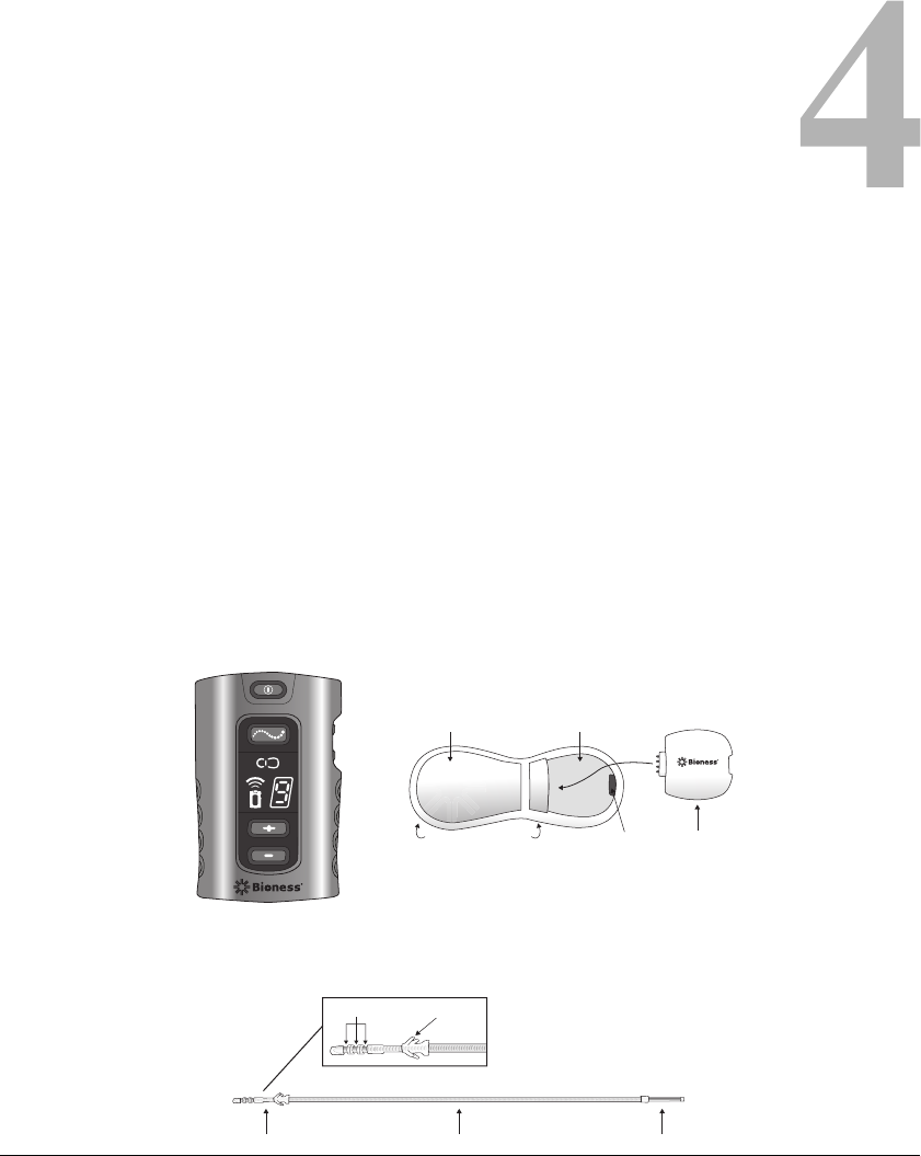
FIGURE 4-1. Your StimRouter system components.
FIGURE 4-1.
Anchor
Stimulation End Lead Body Pick-up End
3 Electrodes
EPT CradleIntegrated Battery
Surface Gel Electrodes
(on the bottom)
EPT
EPT Latching
Mechanism
Remote Control User Patch and EPT
(Top Down View)
Implantable Lead

4-14 StimRouter User Manual
Implantable Lead
The StimRouter lead is about 6 inches long. It has a stimulation end and a
pick-up end. The entire lead is implanted.
Stimulation End
Stimulates the treatment area.
Pick-Up End
Receives (picks up) the stimulation signal from the external pulse
transmitter and sends it to the stimulation end. The pick-up end can
usually be felt by palpating the skin in the area of implant.
User Patch
The user patch is designed for short-term use and is worn on the skin
directly over the pick-up end of the StimRouter lead. The user patch
features two surface gel electrodes, an integrated battery and a cradle for
the external pulse transmitter. The User Kit comes with several user
patches, and with accessories for storing and carrying the patches.
Design Features
Two Surface Gel Electrodes
Used to adhere the user patch to the skin. Also used to emit the electrical
signal from the external pulse transmitter to the pick-up end of the
implanted lead.
Integrated Battery
Supplies the energy for the external pulse transmitter.
External Pulse Transmitter Cradle
Holds the external pulse transmitter.
EPT Latching Mechanism
Keeps the external pulse transmitter (EPT) in place.

Device Description 4-15
Accessories
User Patch Carrying Case
Designed to carry an extra user patch or store a worn user patch. The case
is small and portable and holds one user patch.
Patch Sleeves
Designed to help secure the user patch to the skin.
External Pulse Transmitter
The StimRouter external pulse transmitter (EPT) sends pain-relieving
electrical stimulation to the implanted lead. The external pulse
transmitter fits into the user patch and responds to wireless commands
from the remote control. The external pulse transmitter is powered by the
battery in the user patch.
The external pulse transmitter is transferred to a new user patch when a
worn patch is disposed of.
Remote Control
The StimRouter remote control communicates wirelessly with the
external pulse transmitter, turning stimulation on and off, fine-tuning
stimulation intensity and controlling program selection. The remote
control contains a rechargeable battery, and can contain up to eight
stimulation programs. The remote control is small enough to be worn
around the neck or wrist, or carried in a pocket or belt pouch.
Operating Modes
Standby
In standby mode, the remote control is activated and waiting for
commands. The remote control starts in standby mode when first turned
on, and returns to standby mode when program mode and stimulation
mode are exited.
4-16 StimRouter User Manual
Program
In program mode, the available stimulation programs are accessible. To
choose a stimulation program, use the plus/minus buttons.
Stimulation
In stimulation mode, the StimRouter system is on; it is stimulating the
target treatment area. Stimulation intensity can be fine-tuned using the
plus/minus buttons.
Operating Buttons
On/Off
Used to turn the remote control on and off. (The remote control turns off
automatically after 5 minutes of disuse.)
Mode
Used to select one of three operating modes: program, stimulation or
standby.
Plus/Minus
Used to fine-tune stimulation intensity and select a stimulation program.
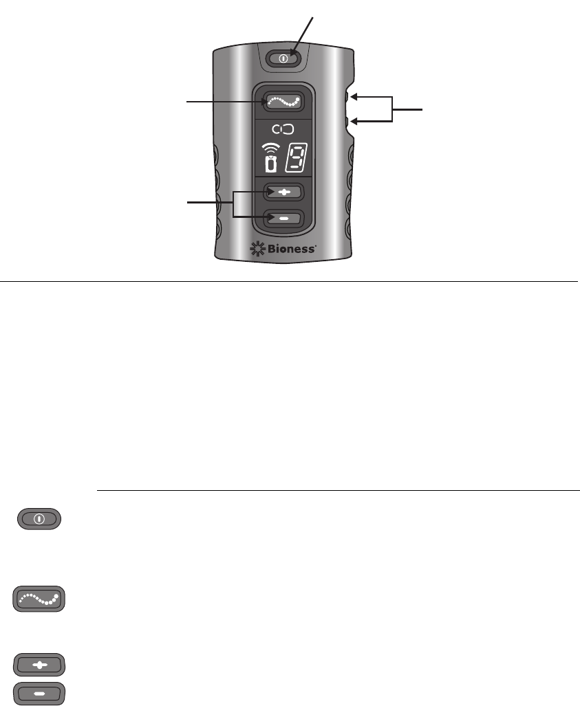
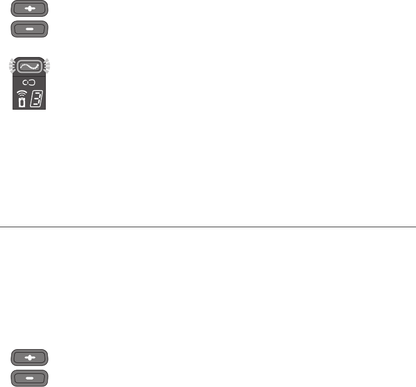
FIGURE 4-2. StimRouter remote control operating buttons.
On/Off Button
Plus/ Minus Buttons
Volume Buttons
Mode Button
Device Description 4-17
Volume
Used to increase or decrease sound level of the audio indicators.
On/Off Indicator Lights
Remote Control
On/Off button flashes green when the remote control is on.
Stimulation
Mode button flashes yellow when stimulation mode is on.
Program
Mode button glows yellow when program mode is on.
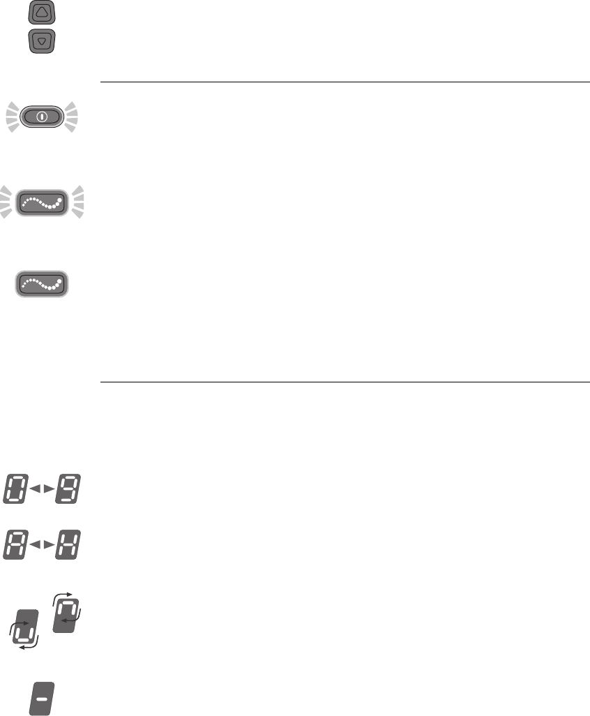
Digital Display
Shows stimulation intensity in stimulation mode, program selected in
program mode, charging status, radio frequency registration status and
system errors.
Intensity
Displayed as “0–9” in stimulation mode.
Program
Displayed as “A–H” in program mode.
Battery Charging
A small green loop circles in the digital display. The loop appears in the
lower half of the display when charge level is low and in the upper half
when charge level is high.
Battery Fully Charged
A horizontal green line appears in the digital display.
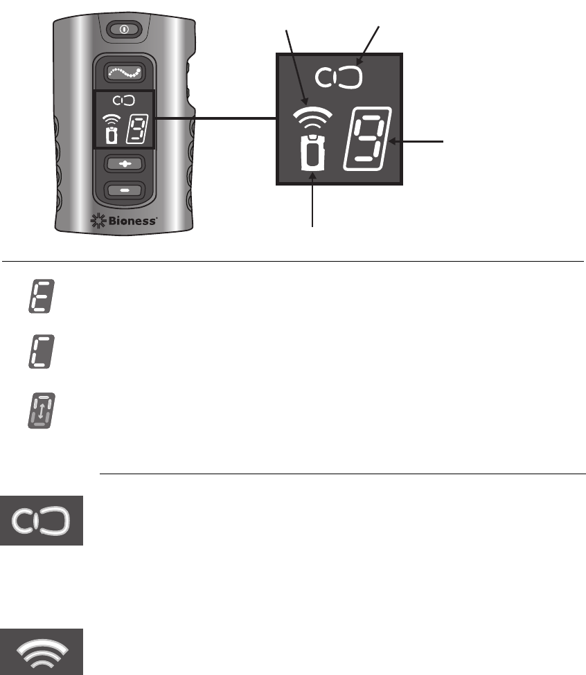
FIGURE 4-3. StimRouter remote control digital display and LEDs.
4-18 StimRouter User Manual
Radio Frequency Registration Error
“E” appears in the digital display.
Radio Frequency Registration Complete
“C” appears in the digital display.
Radio Frequency Registration in Progress
A green arch alternates in the digital display.
LEDs
User Patch Icon
• Flashes red: faulty electrode contact or temperature error in the
external pulse transmitter
• Glows red: component malfunction
• Flashes yellow: low battery
Radio Frequency (RF) Icon
• Flashes red: radio frequency error
• Glows green for a few seconds: RF registration is complete
User Patch Icon
Digital Display
Remote Control Icon
Radio Frequency
(RF) Icon
Device Description 4-19
Remote Control Icon
• Flashes yellow: low battery
• Glows red: component malfunction or battery charging error
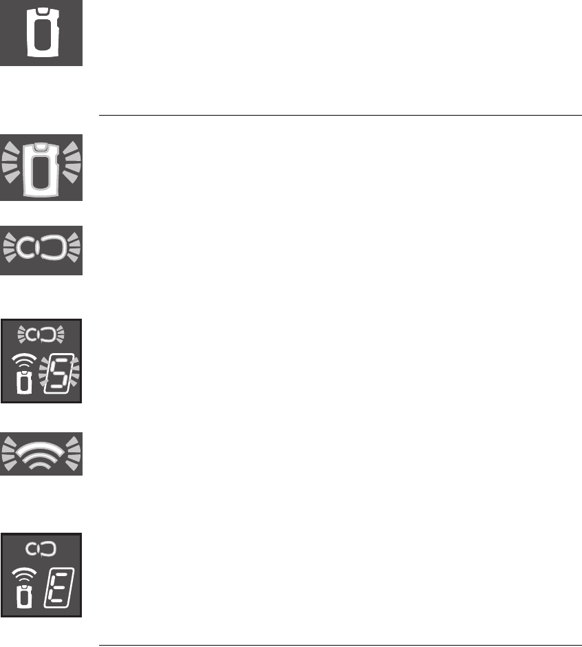
Visual Alerts
Low Battery, Remote Control
•Remote control icon flashes yellow
Low Battery, User Patch
•User patch icon flashes yellow
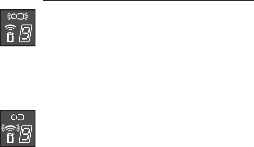
Faulty Electrode Contact
•User patch icon flashes red
•Stimulation intensity number flashes green
Radio Frequency Failure
•Radio frequency icon flashes red
Component Malfunction
•Remote control or user patch icon glows red
•“E” appears in the digital display
Audio Alerts
Beep
The remote control beeps to indicate:
•The remote control is activated

4-20 StimRouter User Manual
•A button has been pressed
•The stimulation mode’s duration has elapsed
•The remote control battery charge level is low
•The remote control battery is depleted
•The remote control battery is full
•The electrode contact is faulty
•The user patch battery is low
•The EPT is malfunctioning
•The remote control charger is connected
•The remote control charger is disconnected
Battery Compartment
The battery compartment contains a rechargeable AAA battery
(installed). Refer to page 9-39 for battery replacement instructions.
Accessories
Remote Control Charger
Used to recharge the remote control battery.
Remote Control Neck Strap
Loops through the top of the remote control and is used to carry the
remote control.
Remote Control Wrist Strap
Loops through the top of the remote control and is used to carry the
remote control.
Remote Control Pouch
Features a clamp for attachment to a belt and is used to carry the remote
control.

Technical Specifications 5-21
CHAPTER
Specifications, StimRouter User Patch
Classification Internally powered, continuous operation, Type BF applied part(s)
Battery Type 2 AAA 1.5-V, lithium batteries
Dimensions Height
14 mm (0.551 in.)
Width
40 mm (1.574 in.)
Length
115 mm (4.527 in.)
Weight
Environmental Ranges Transport and Storage Temperature
0°C to 60°C (32°F to 140°F)
Operational Conditions Temperature
15°C to 40°C (59°F to 104°F)
Charging Temperature
5°C to 40°C (41°F to 104°F)
Relative Humidity
25% to 85%
Atmospheric Pressure
0.9 kPA to 1.060 kPA
C
HAPTER
5
T
ECHNICAL
S
PECIFICATIONS
Specifications, StimRouter External Pulse Transmitter
Classification Externally powered, continuous operation, Type BF applied parts
Operating Voltage 3 V

5-22 StimRouter User Manual
Dimensions Height
9 mm (0.354 in.)
Width
35 mm (1.377 in.)
Depth
38 mm (1.496 in.)
Weight 10 grams (0.352 oz.)
Environmental Ranges Transport and Storage Temperature
-20°C to 60°C (-4°F to 140°F)
Operational Conditions Temperature
5°C to 40°C (41°F to 104°F)
Charging Temperature
5°C to 40°C (41°F to 104°F)
Relative Humidity
25% to 85%
Atmospheric Pressure
0.9 kPA to 1.060 kPA
Specifications, StimRouter Remote Control
Classification Internally powered, continuous operation
Operational Modes Standby, program, stimulation
Battery Type Rechargeable AAA NiMH 1.2-V, 1100 mAh
Operating Buttons On/Off
Used to turn the remote control on and off
Mode
Used to select one of three operating modes: program, stimulation
or standby
Plus/Minus
Used to fine-tune stimulation intensity and change stimulation
programs
Volume
Used to increase or decrease sound level of the audio indicators
LEDs User Patch Icon
User patch and external pulse transmitter status
Radio Refrequency Icon
Remote control and external pulse transmitter radio
communication status
Remote Control Icon
Remote control status
Specifications, StimRouter External Pulse Transmitter

Specifications, Remote Control Power Supply
Use medical Class II safety approved power supply provided/approved by Bioness
Inc. with the following ratings:
Input
Voltage 100–240 V AC
Current 200 mZ
Frequency 50–60 Hz
Output
Voltage 5 V ± 5%
Current 1300 mA
Technical Specifications 5-23
Digital Displays Relative stimulation intensity
Program selected
Error or status (charging, registration)
On/Off Indicator Lights Remote Control
Stimulation
Program
Audio Alerts Beep
System errors
Mode changes (stimulation and program)
Volume changes
Carrying Options Neck strap, wrist strap, belt pouch, pocket
Dimensions Height
71 mm (2.8 in.)
Width
46 mm (1.8 in.)
Depth
17.5 mm (0.7 in.)
Weight 45 grams (1.5 oz.)
Environmental Ranges Transport and Storage Temperature
-20°C to 60°C (-4°F to 140°F)
Operational Conditions Temperature
5°C to 40°C (41°F to 104°F)
Charging Temperature
5°C to 40°C (41°F to 104°F)
Relative Humidity
25% to 85%
Atmospheric Pressure
0.9 kPA to 1.060 kPA
Specifications, StimRouter Remote Control

Specifications, Wireless Link
Frequency Band 2.4 GHz, ISM band
Transmission Power Complies with FCC 15.247 (for U.S.)
5-24 StimRouter User Manual

Environmental Conditions that Affect Use 6-25
CHAPTER
C
HAPTER
6
E
NVIRONMENTAL
C
ONDITIONS
THAT
A
FFECT
U
SE
Storage and Handling
All StimRouter components should be kept dry and protected from
extreme changes in temperature and humidity. Do not use or store your
components where they could come in contact with water, such as by
sinks, bathtubs and shower stalls. Do not expose your StimRouter
components to weather conditions such as rain or snow, or to any other
source of water.
Do not store your StimRouter components in a car or elsewhere where
hot or cold weather temperatures could exceed the acceptable ranges of
the components. See Appendix. Temperature extremes can damage the
StimRouter components.
To avoid condensation when transporting your StimRouter components
from hot to cold temperatures, place the components in an air-tight
plastic bag first. Let them adjust slowly (for at least two hours) to the
change in temperature before use.
Radio Communication Information
Several components of the StimRouter system communicate via radio
communication and have been tested and found to comply with the limits

6-26 StimRouter User Manual
for a Class B digital device, pursuant to Part 15 (Radio Frequency
Devices) of the FCC Rules. These limits are designed to provide
reasonable protection against harmful interference in a residential
environment. This equipment generates, uses and can radiate radio
frequency energy and, if not operated and used in accordance with the
instructions, may cause harmful interference to radio communications.
However, there is no guarantee that interference will not occur in a
particular environment. If this equipment does cause harmful interference
to radio or television reception, which can be determined by turning the
equipment off and on, try to correct the interference by one or more of
the following measures:
•Reorient or relocate the receiving antenna
•Increase the separation between the equipment and receiver
Consult the dealer or an experienced radio/television technician for
assistance.
The antenna for each transmitter must not be located near to or operating
in conjunction with any other antenna or transmitter.
Changes or modifications to the StimRouter system not expressly
approved by Bioness Inc. could void the user’s authority to operate the
equipment.
Security Screening Devices
Certain types of antitheft devices, such as those used at the entrances and
exits of public buildings such as libraries, airports and retail stores, may
affect stimulation. Use caution when approaching a security screening
device. Ask for assistance to bypass the device by showing your patient
ID card. If you must pass through such a device, make certain that the
stimulation is turned off on your StimRouter system, and pass through
the device quickly.
Cell Phones
While we do not anticipate any interference with cell phones, the full
effects of interaction with cell phones are unknown at this time.

Set-Up Instructions 7-27
CHAPTER
C
HAPTER
7
S
ET
-U
P
I
NSTRUCTIONS
Charging the Remote Control
The remote control comes with a rechargeable AAA battery already
installed, and a charger. The battery should be charged daily and when
the remote control icon flashes yellow.
A new remote control battery supports at least 24 hours of typical usage
before needing to be recharged.
The remote control can be operated while it is being charged.
WARNING:
Use only the charger included in the StimRouter User Kit. Use of any
other charger can result in serious injury.
To charge the remote control battery:
1Open the cover over the charging socket on the bottom of the remote
control.
2Insert the charger cable connector into the charging socket.
3Plug the charger into a power socket.
4Monitor the remote control digital display to verify that the remote
control is charging. When the remote control battery is charging and
the remote control is in standby mode, a small green loop will circle
in the digital display. The loop will circle in the lower half of the
display when the charge level is low. It will circle in the upper half
when the charge level is high. FIGURE 7-1.

7-28 StimRouter User Manual
5The charging process should last approximately four hours.
6When the remote control battery is fully charged, a horizontal green
line will appear in the digital display.
7Unplug the charger cable from the power socket and from the
charger socket. Store the charger in the User Kit.
FIGURE 7-1. When the remote control is turned off, the digital display continuously
shows the charging status. In standby, stimulation or program mode, the charging
status appears only briefly when the charger is first connected.
Charge
Level Low
Charge
Level High
Battery
Charged
Preparing the Skin
For optimal stimulation, the skin below the user patch should be clean
and dry.
CAUTION:
If the skin is inflamed or swollen, do not use the StimRouter. Inflammation
in the region of the user patch may be aggravated by pressure from the
user patch. Use of the StimRouter should be temporarily halted until the
inflammation is resolved.
To prepare the skin:
1Locate the area where the pick-up electrode is implanted. If
necessary, palpate the area until the pick-up electrode can be felt.
2Clean the skin above the pick-up electrode with an alcohol swab or
wet washcloth and dry. If the area has been treated with lotions or
oils, then clean the skin with soap and water, rinse well and dry.
If necessary, remove excess body hair from the skin area with scissors.
Do not use a razor. A razor can irritate the skin.

Operating Instructions 8-29
CHAPTER
C
HAPTER
8
O
PERATING
I
NSTRUCTIONS
CAUTION:
Use only the Bioness components designed and manufactured for the
StimRouter. Do not substitute any components for those supplied in the
StimRouter User Kit.
Overview
This section includes the following instructions for performing a
StimRouter treatment session:
•Attaching the External Pulse Transmitter to a User Patch
•Applying the User Patch to the Skin
•Turning On the Remote Control
•Adjusting the Volume Level of Audio Alerts
•Selecting a Stimulation Program
•Turning Stimulation On
•Adjusting Stimulation Intensity
•Saving a New Default Stimulation Level
•Turning Stimulation Off
•Taking Off the User Patch
•Removing the External Pulse Transmitter

8-30 StimRouter User Manual
Before operating the StimRouter, read the previous sections of this
manual that describe the components and their features. To gain the
maximum benefit from your StimRouter, carefully follow your
clinician’s instructions. If you have any questions or problems, or
experience any new symptoms or painful areas, contact your treating
clinician for appropriate diagnosis and treatment. Your clinician is
familiar with your specific situation and the best source of additional
guidance.
Attaching the EPT to a User Patch
To attach the external pulse transmitter (EPT) to a user patch:
1Hold the EPT with the label facing toward the user patch.
2Align the gold connector on the EPT with the connector’s port on
the user patch. Push the EPT forward into the port. Press the EPT
into the cradle on the user patch to lock the latching mechanism.
Note:
To ensure proper electrical stimulation, the external pulse transmitter
must be connected to the user patch properly.
Applying the User Patch to the Skin
A user patch can be reused for as long as its battery is functional and its
gel electrodes can adhere to the skin.
WARNING:
Do not touch the gel electrodes with both hands while stimulation is
turned on; serious injury could result from electrical current passing
through the body. Stimulation should be turned off before adhering,
removing or handling the user patch.
Do not apply the user patch to anyone else or any other part of the body
than that determined by the treating clinician.
Before putting the user patch on, remove the gel electrode cover and
store the cover in the user patch carrying case. (Reapply the cover
whenever the user patch is stored.)
To put the user patch on:

Operating Instructions 8-31
1Locate the area where the pick-up electrode is implanted. If
necessary, palpate the area until the pick-up electrode can be felt.
2Clean the skin above the pick-up electrode with an alcohol swab or
wet washcloth and then dry the skin area. If the area has been treated
with lotions or oils, then clean the skin with soap and water, rinse
well and dry. If necessary, remove excess body hair from the skin
area with scissors. Do not use a razor. A razor can irritate the skin.
3Hold the user patch between the index finger and thumb, with the
gel electrodes facing toward the site of adhesion.
CAUTION:
Do not pinch or stretch the skin while adhering the user patch.
4Orient the user patch so that the center of one of the gel electrodes is
positioned directly over the pick-up end of the lead. If the user patch
is not placed directly over the pick-up end of the lead, stimulation
may be uncomfortable or ineffective.
CAUTION:
Make certain that the adhesion site is free from any obstructions, i.e.,
bandages, clothing, etc., before adhering the patch. Placing the user patch
partially or wholly over a bandage or other obstruction could cause skin
irritation or tissue damage during stimulation.
5Firmly adhere the user patch to the skin, making sure that the patch
is in full contact with the skin.
If the user patch is not firmly adhered
to the skin and moves, stimulation may become uncomfortable or
ineffective.
Turning On the Remote Control
Note:
The remote control must be within 10 feet of the external pulse
transmitter when the system is activated to ensure optimal radio
communication. If the components are not within 10 feet of each other, the
radio frequency icon will flash red.
Remote Control Off Remote Control On
The remote control on/off button is located at the top of the remote
control front panel.
8-32 StimRouter User Manual
To turn the remote control on:
1Press the on/off button once and release. The remote control will
beep and start a self test. All display indicators will light up briefly.
When the self test is finished, the remote control will beep again, the
lights will turn off, and the on/off button will flash green.
Note: The remote control turns on in standby mode. The default
stimulation intensity level will appear as a number in the digital display.
To turn the remote control off:
2Press the on/off button once and release. The remote control will
beep and turn off. The on/off button will stop flashing. (The remote
control turns off automatically after 5 minutes of disuse.)
Adjusting the Volume of Audio Alerts
The volume control buttons are located on the right side of the remote
control (up/down arrows). Each time an arrow is pressed, the remote
control will beep to demonstrate the new sound level.
Tomute the audio alerts:
1Press and hold the down arrow for at least three seconds or decrease
the volume to the minimal level.
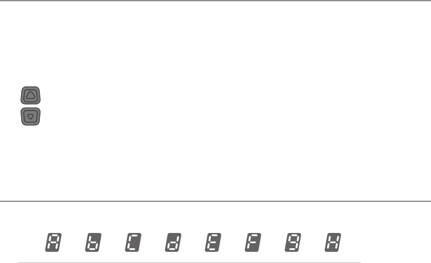
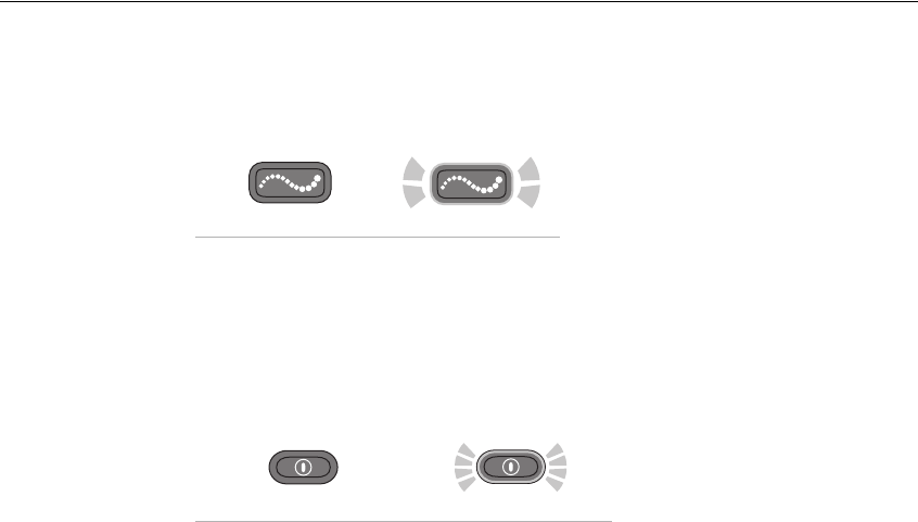
FIGURE 8-1. Stimulation programs A–H, as represented on the digital display.
When the remote control is turned off, the active volume level is saved. If
the active level is “mute,” the default volume setting is restored when the
remote control is turned back on.
Selecting a Stimulation Program
The remote control can store up to eight clinician-set stimulation
programs. These programs are labeled “A–H” and can be selected using
the plus/minus buttons in program mode. See FIGURE 8-1.
Operating Instructions 8-33
To select a stimulation program:
1From standby mode, press and hold the mode button for at least
three seconds, until the remote control beeps and the mode button
glows yellow. A letter will appear in the digital display, indicating
the active program.
2Press the plus or minus button to change the active program. The
new active program will appear in the digital display.
3Press the mode button briefly to return to standby mode. The remote
control will beep, the mode button will turn off, and the default
stimulation intensity level will appear in the digital display.
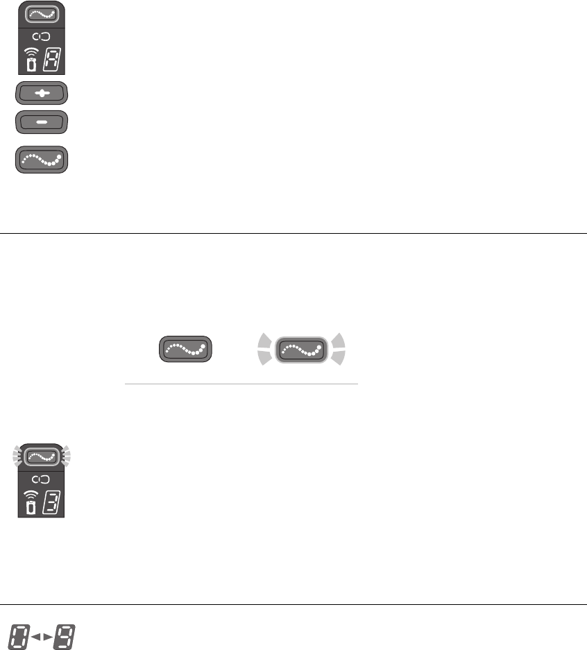
Turning Stimulation On
Stimulation Off Stimulation On
To turn stimulation on:
1From standby mode briefly press the mode button. The remote
control will beep and the mode button will start flashing yellow.
2Few a few seconds, the digital display will alternately show the
active program and active stimulation intensity level.
3After a few seconds, the digital display will show only the
stimulation intensity level.
4After a few minutes, the digital display will go dark.
Adjusting Stimulation Intensity
The remote control stores up to nine stimulation intensity settings. These
settings are numbered “1–9”; “0” equals no stimulation. When the
remote control is first turned on, the stimulation intensity level should be
“5,” which is the customary default level set by the clinician. Normally,
8-34 StimRouter User Manual
this level will be most appropriate for use. Stimulation intensity can be
adjusted, however, using the plus/minus buttons.
CAUTION:
Be careful not to set the stimulation intensity too high. Pain can result.
To temporarily adjust stimulation intensity:
1Either from standby mode or while stimulating in stimulation mode,
press the plus or minus button once for each level of change. The
remote control will beep and the new level will show on the digital
screen.
2Allow time for the system to demonstrate a change in setting before
making another change.
CAUTION:
If the intensity level is changed while stimulation has cycled off in
stimulation mode, or while the system is in standby mode, the new
intensity level will not activate until the system cycles back on. Be certain
to test each level before advancing stimulation to a different level,
especially to a higher level.
Saving a New Default Stimulation Intensity Level
You can save a new default stimulation intenstity level for each program
stored on the remote control.
To save a new default stimulation intensity level:
1Select a stimulation program (“Selecting a Stimulation Program” on
page 8-32).
2Return to standby mode.
3Adjust the stimulation intensity level to the desired level
(“Adjusting Stimulation Intensity” on page 8-33).
4From standby mode, press and hold the minus button for at least
three seconds. The remote control will beep and the new default
intensity level will flash on the digital display for a few seconds
while saving.
Operating Instructions 8-35
The saved level will be the default level whenever the stimulation
program is started or until a new default level is saved.
Turning Stimulation Off
Stimulation Off Stimulation On
To turn stimulation off:
1Press the mode button briefly. The remote control will return to
standby mode and the mode button will turn off. Stimulation will
stop.
Remote Control Off Remote Control On
2Or, turn the remote control off. The remote control can be turned off
at all times. When the remote control is turned off, stimulation will
stop.
Note:
The remote control is designed to mitigate unintentional stimulation
or stimulation at an intensity level that is too high. If stimulation is
inadvertently set too high or turned on unintentionally, and cannot be
corrected using the remote control, remove the user patch. If the remote
control malfunctions, or an unexpected response or stimulation level is
experienced, take the user patch off and contact Bioness Customer
Support.

8-36 StimRouter User Manual
Taking Off the User Patch
Note:
Remove the user patch before bathing, when the battery wears out
and when the gel adhesive, with or without the assistance of a patch sleeve
or strap, can no longer keep the user patch in place.
Periodically, the user patch will also need to be removed to allow the skin
to breathe. Skin irritation can result from prolonged contact with the
surface gel electrodes.
To remove the user patch:
1Stop stimulation and turn the remote control off.
2If a patch strap or sleeve was used, take the strap off.
3Grasp the tab on the user patch and gently pull the patch away from
the skin.
4Place the electrode cover over the gel electrodes.
5If the user patch is still operational, store the patch in the user patch
carrying case.
6If the user patch is no longer operational, remove the external pulse
transmitter (EPT) from the user patch and dispose of the patch
according to local regulations.
Note:
Do not dispose of the EPT.
Removing the External Pulse Transmitter
To remove the external pulse transmitter (EPT):
1Gently pull the latching mechanism on the user patch back and away
from the EPT.
2Lift out the EPT.
Note:
Do not dispose of the EPT.
3Store the EPT in the User Kit or the user patch carrying case, or
attach it to a new user patch.
Operating Instructions 8-37
8-38 StimRouter User Manual

Maintenance and Cleaning 9-39
CHAPTER
C
HAPTER
9
M
AINTENANCE
AND
C
LEANING
CAUTION:
Do not attempt to repair any of the components supplied in the StimRouter
User Kit. If a component malfunctions or is lost, contact Bioness Customer
Support.
Recharging the Remote Control Battery
The remote control battery should be charged daily, after extended
storage and when the remote control icon flashes yellow. The battery
must be charged for stimulation to be effective and comfortable. See
“Charging the Remote Control” on page 7-27.
Replacing the Remote Control Battery
The remote control battery should be replaced approximately every two
years.
To replace the battery:
1Remove the screw from the battery cover on the back of the remote
control. The screw is under a label. Gently peel up the corner of the
label, taking care not to damage the label.
2Remove the battery cover.
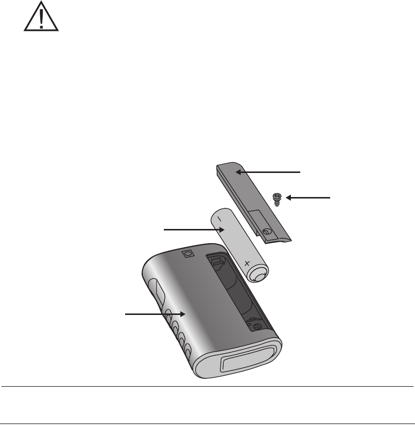
9-40 StimRouter User Manual
3Remove the old battery.Insert a new rechargeable AAA NiMH 1.2-
V battery, orienting it to match the polarity marks on the battery
socket.
WARNING:
Use only a rechargeable 1.2-V NiMH AAA battery. Use of a non-
rechargeable battery can damage and overheat the remote control, and
may lead to tissue injury or burns.
4Reattach the battery cover.
5Tighten the screw.
6Reattach the label.
7Dispose of the old battery according to your local environmental
regulations.
FIGURE 9-1. Diagram for opening the remote control battery compartment.
Remote Control
Battery
Screw
Battery Cover
Registering a New Component
When you replace your remote control or external pulse transmitter, the
new working components must be electronically registered to each other
for your StimRouter to operate.
Maintenance and Cleaning 9-41
To perform the registration procedure, both the remote control and the
external pulse transmitter must be operational. Make sure the remote
control is charged and that the external pulse transmitter is attached to a
user patch with a working battery.
Note
: Please read all of the instructions below before beginning the
registration procedure.
To register the remote control and the external pulse transmitter:
1If necessary, charge the remote control.
2Ensure that the remote control is turned off (the on/off button should
not be flashing green).
Remote Control Off Remote Control On
3Attach the external pulse transmitter to a user patch with a working
battery.
4Place the remote control and user patch with external pulse
transmitter attached close together on a table. Make sure the remote
control and the external pulse transmitter are no more than a few
inches apart and not touching.
5Make certain that any other external pulse transmitter is at least 10
feet away from the components to be registered.
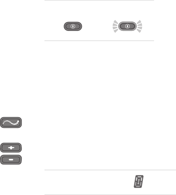
6Simultaneously press and hold for three seconds the mode and
minus buttons on the remote control to start the registration process.
You should hear a beep, indicating the registration process has
begun.
7The remote control digital readout should display two alternating
green arches, indicating registration is in progress.
Registration in Progress

9-42 StimRouter User Manual
8When the readout displays the letter “C” (meaning connected), and
the radio frequency icon turns green for a few seconds, registration
is complete. The system will automatically turn on. If the radio
frequency icon is not flashing red, registration was successful.
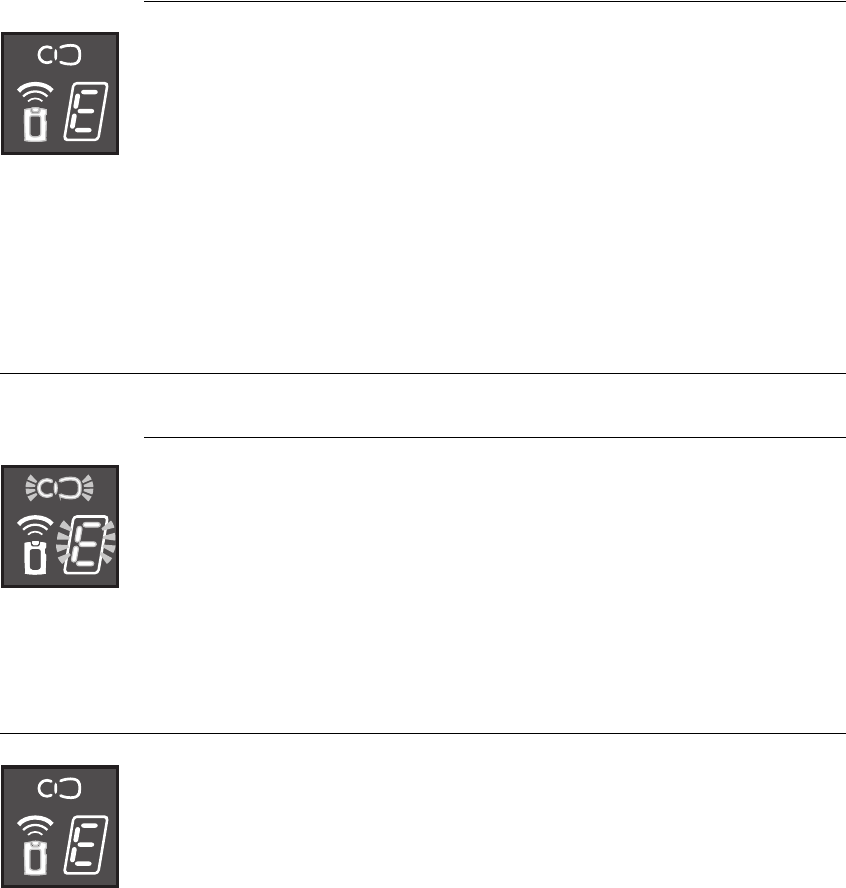
Note:
If the readout displays the letter “E” (meaning error) and the radio
frequency icon turns red for a few seconds, an error has occurred and the
procedure must be repeated. If the error indication continues to appear,
contact Bioness Customer Support.
Replacing the User Patch
The user patch is disposable; when the battery loses its charge or the gel
electrodes lose their adhesiveness and do not provide stable positioning
with or without the aid of a patch sleeve, dispose of the patch according
to your local regulations.
To replace a user patch:
1Stop stimulation and turn the remote control off.
2If a patch sleeve was used, take the sleeve off.
3Grasp the patch tab and gently pull the patch from the skin.
4Place the electrode cover over the gel electrodes.
5Gently pull the latching mechanism back and away from the
external pulse transmitter (EPT) and lift out the EPT.
Note:
Do not discard the EPT.
6Open a new user patch.
7Hold the EPT with the label facing toward the new user patch.
Registration Connected
Registration Error

Maintenance and Cleaning 9-43
8Align the gold connector on the EPT with the connector’s port on
the user patch. Push the EPT forward into the port. Press the EPT
toward the patch to lock the latching mechanism.
Note:
To ensure proper electrical stimulation, the external pulse
transmitter must be connected to the user patch properly.
Cleaning the Components
•All StimRouter components may be cleaned by carefully wiping
with a damp cloth.
•StimRouter electronic components are not waterproof; do not
immerse them in water to clean.
Cleaning the Patch Sleeves
•Wash by hand in lukewarm water, separately from other items
•Hang dry in shade without folds
•Do not iron
•Do not dry in a dryer
•Do not leave the sleeves rolled up when wet
•Avoid contact with rough or hard surfaces
•Avoid contact with lotions, oils and other chemicals
9-44 StimRouter User Manual

Troubleshooting 10-45
CHAPTER
C
HAPTER
10
T
ROUBLESHOOTING
Should a technical problem occur that is not covered in this section,
contact Bioness Customer Support: Telephone: (800) 211-9136.
Note:
Do not attempt to repair any of your StimRouter components.
User Patch
Faulty Electrode Contact
Indicators
•Beep
•User patch icon flashes red
•Intensity level flashes in digital display
Corrective Actions
1Turn off the remote control.
2Remove the user patch from the body.
3Check to see that the electrode cover was removed from the patch.
4Make sure that nothing is on the electrodes or on the skin that would
interfere with electrode contact with the skin.
10-46 StimRouter User Manual
5Check to see that the external pulse transmitter is snugly attached to
the user patch.
6Re-adhere the user patch to the skin.
7If the problem persists, adhere a new user patch.
8If the problem persists, contact Bioness Customer Support.
Battery Low Charge
Indicators
•Beep
•User patch icon flashes yellow
Corrective Actions
1Change the user patch.
2If the problem persists, contact Bioness Customer Support.
Battery Failure
Indicator
•Radio frequency icon flashes red
Corrective Actions
1Reattach the external pulse transmitter to the same user patch.
2Replace the user patch. Use a new user patch and connect the
external pulse transmitter to the new patch.
3If the problem persists, contact Bioness Customer Support.

Troubleshooting 10-47
Remote Control
Battery Low Charge
Indicators
•Beep
•Remote control icon flashes yellow
Corrective Actions
1Charge the remote control battery.
2If the problem persists, replace the battery.
Battery Failure
Indicator
•When the remote control is turned on, none of the icons lights up; no
self test is performed
Corrective Actions
1Charge the battery.
2If the problem persists, replace the battery.
Battery Discharges Rapidly
Indicator
•Remote control battery discharges rapidly (the battery should last
for about 24 hours of normal use)
Corrective Action
1Replace the battery.
10-48 StimRouter User Manual
Battery Charging Error
Indicator
•While charging, the letter “E” appears on the digital display and the
remote control icon glows red
Corrective Actions
1Reconnect the charger cable to the remote control.
2If the problem persists, replace the battery in the remote control.
3If the problem persists, contact Bioness Customer Support.
External Pulse Transmitter
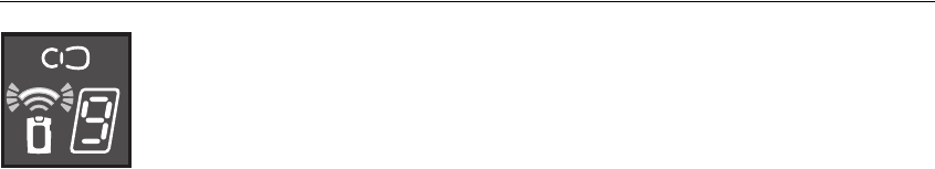
Temperature Error
Indicator
•The user patch icon flashes red and “E” flashes in the digital display
Corrective Action
1The external pulse transmitter is either too hot or too cold and will
cease activity until its working temperature range is restored.
Component Malfunction
Indicators
•Beep
•User patch icon is glows red or remote control icon glows red
and“E” appears in the digital display
Corrective Actions
1Turn off the remote control and then turn it back on.
2If the problem persists, contact Bioness Customer Support.
Troubleshooting 10-49
Radio Communication Failure
Indicators
•Beep
•The radio frequency icon flashes red
Corrective Actions
1Make sure that the remote control and the external pulse transmitter
(EPT) are within 10 feet of each other.
2Make sure that the remote control battery is charged.
3If the components are within range and working properly, turn the
remote control off and then back on.
4Check to see that the external pulse transmitter is snugly attached to
the user patch.
5Replace the user patch: use a new user patch and connect the
external pulse transmitter to the new patch.
6If the problem persists, reregister the components.
7If the problem still persists, contact Bioness Customer Support.
10-50 StimRouter User Manual
A
A-H 32
airports 26
antitheft devices 26
B
battery discharges rapidly 47
battery loses its charge 42
C
charger cable connector 27
charging socket 27
clinician-set stimulation programs 32
condensation 25
D
default configuration 35
default volume setting 32
dispose of the patch 42
E
electronically registered 40
G
gel electrode cover 30
gel electrodes lose their adhesiveness 42
gold connector on the EPT 43
H
handling the user patch 30
horizontal green line 28
hot to cold temperatures 25
I
Intensity level flashes in digital display 45
L
latching mechanism 42
letter “C” 42
letter “E” 42, 48
letter “E” flashes 48, 49
M
mute 32
P
patient ID card 26
R
rain or snow 25
rechargeable AAA battery 27
Registration Connected 42
Registration Error 42
Registration in Progress 41
remote control and user patch icons start flash-
ing red in succession 48, 49
remote control icon flashes yellow 27
remote control icon turns red 48
Remote control indicator flashes yellow 47
Remote control indicator is constantly red 48
remote control malfunctions 35
remove the user patch 36
replace the battery 39
S
saved configuration 35
security screening device 26
stimulation intensity too high 34
stimulation is inadvertently set too high 35
T
television reception 26
two alternating green arches 41
typical usage 27
U
unexpected response 35
User patch icon flashes red 45
User patch icon is constantly red 48
User patch indicator flashes yellow 46
W
weather 25
Index