Biotronik BELOS-T Belos DR-T, Belos VR-T, and Cardiac Airbag-T User Manual Belos Family of ICDs
Biotronik, Inc. Belos DR-T, Belos VR-T, and Cardiac Airbag-T Belos Family of ICDs
Contents
- 1. Belos User Manual
- 2. Cardiac Airbag User Manual
Cardiac Airbag User Manual
(Draft)
Cardiac Airbag /
Cardiac Airbag-T
Family of Implantable Cardioverter
Defibrillators and Software Cartridge for
TMS 1000PLUS and EPR 1000PLUS
Technical Manual

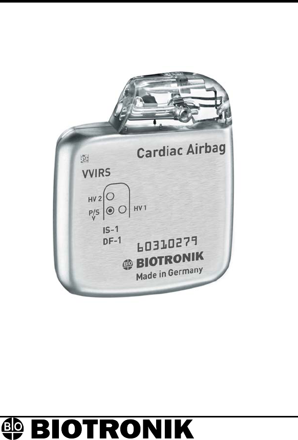
X-ray Identification
Cardiac Airbag/Cardiac Airbag-T
Implantable Cardioverter Defibrillator
Inside the housing, top left-hand side:
Year of manufacture
X-Ray identification
EI•
CAUTION
Federal (U.S.A.) law restricts this device to sale by, or on the
order of, a physician.
2003 BIOTRONIK, Inc., all rights reserved.

Cardiac Airbag Technical Manual i
Contents
1. General...........................................................................1
1.1 System Description....................................................1
1.2 Indications and Usage ...............................................2
1.3 Contraindications .......................................................2
1.4 Warnings and Precautions.........................................3
1.4.1 Sterilization, Storage, and Handling ..................3
1.4.2 Device Implantation and Programming..............4
1.4.3 Lead Evaluation and Connection.......................6
1.4.4 Follow-up Testing...............................................7
1.4.5 Pulse Generator Explant and Disposal..............8
1.4.6 Hospital and Medical Hazards ...........................9
1.4.7 Home and Occupational Hazards......................11
1.4.8 Cellular Phones..................................................11
1.4.9 Electronic Article Surveillance (EAS).................12
1.4.10 Home Appliances...............................................12
1.5 Adverse Events..........................................................13
1.5.1 Potential Adverse Events...................................13
1.5.2 Observed Adverse Events .................................14
1.6 Clinical Studies ..........................................................17
1.6.1 Patients Studied.................................................17
1.6.2 Methods .............................................................18
1.6.3 Results ...............................................................18
1.7 Patient Selection and Treatment ...............................20
1.7.1 Individualization of Treatment............................20
1.7.2 Specific Patient Populations ..............................20
1.8 Patient Counseling Information .................................20
1.9 Evaluating Prospective ICD Patients.........................21
2. Device Features ............................................................22
2.1 Sensing ......................................................................22
2.1.1 Ventricular Sensitivity Settings ..........................22
2.1.2 Minimum Ventricular Threshold .........................25
2.2 Ventricular Tachyarrhythmia Detection ......................25
2.2.1 VF Classifications ..............................................26
2.2.2 VT Interval Counters ..........................................26
2.2.3 VT Classification ................................................26
2.2.4 Onset and Stability .............................................27

ii Cardiac Airbag Technical Manual
2.3 Tachyarrhythmia Redetection ....................................28
2.3.1 VT Redetection ..................................................28
2.3.2 VF Redetection ..................................................28
2.3.3 Tachyarrhythmia Termination ............................28
2.4 Tachyarrhythmia Therapy ..........................................28
2.4.1 Shock Therapy...................................................29
2.5 Bradycardia Therapy .................................................31
2.5.1 Bradycardia Pacing Modes................................31
2.5.2 Basic Rate..........................................................31
2.5.3 Rate Adaptation .................................................31
2.5.4 Gain and Threshold ...........................................32
2.5.5 Rate Increase / Decrease ..................................32
2.5.6 Maximum Sensor Rate ......................................32
2.5.7 Pulse Amplitude .................................................32
2.5.8 Pulse Width........................................................33
2.5.9 Noise Response.................................................33
2.5.10 Post Shock Pacing.............................................33
2.6 Special Features ........................................................33
2.6.1 Home Monitoring (Cardiac Airbag-T Only) ........33
2.6.2 Real-time IEGM Transmission...........................37
2.6.3 Capacitor Reformation .......................................37
2.6.4 Patient and Implant Data ...................................38
2.6.5 System Status....................................................39
2.6.6 Holter Memory ...................................................40
2.6.7 Arrhythmia Induction Features...........................42
2.6.8 Manual Shock ....................................................43
2.6.9 Test Shock .........................................................43
3. Software Features.........................................................44
3.1 Follow-Up Assistant (FAST) Window.........................44
3.1.1 Interrogate ICD without Follow-up .....................45
3.2 Main Function Keys ...................................................45
3.3 Parameter Window ....................................................47
4. Sterilization and Storage ..............................................50
5. Implant Procedure ........................................................52
5.1 Implant Preparation ...................................................52
5.2 Lead System Evaluation ............................................52
5.3 Opening the Sterile Container ...................................53
5.4 Pocket Preparation ....................................................53
5.5 Lead to Device Connection .......................................54

Cardiac Airbag Technical Manual iii
5.6 Blind Plug Connection ...............................................55
5.7 Program the ICD........................................................56
5.8 Implant the ICD..........................................................56
5.9 Suggested Cardiac Airbag Implant Procedure ..........57
6. Follow-up Procedures ..................................................68
6.1 General Considerations.............................................68
6.2 Suggested Cardiac Airbag Follow-Up Procedure......68
6.3 Longevity....................................................................74
6.3.1 Standard ERI Method ........................................74
6.3.2 Treated VF Episode ERI Method.......................76
6.4 Explantation ...............................................................78
7. Technical Specifications ..............................................80
Appendix A...........................................................................85

iv Cardiac Airbag Technical Manual
Cardiac Airbag Specifications
Battery Voltage: 6.3 Volts
Maximum Shock Energy: 30 joules
Defibrillation Lead Ports Two DF-1 (3.2 mm)
Pacing Lead Ports One IS-1 (3.2 mm)
Dimension: 55 x 67 x 13 mm
Volume: 39 cc
Mass: 73 g
Housing Material: Titanium
Header Material: Epoxy Resin
Sealing Plug Material: Silicone
Battery Composition Li / MnO2

Cardiac Airbag Technical Manual 1
1. General
1.1 System Description
The Cardiac Airbag family of Implantable Cardioverter
Defibrillators (ICDs) detects and treats ventricular
tachyarrhythmias as well as provides rate adaptive bradycardia
pacing support. The ICDs are designed to collect diagnostic data
to aid the physician’s assessment of a patient’s condition and the
performance of the implanted device. The Cardiac Airbag ICDs
are specifically designed to have reduced complexity for implant
and follow-up, yet provide essential therapies for conversion of
life threatening ventricular tachyarrhythmias.
There are 10 programmable parameters to simplify the implant
procedure, and detailed diagnostic information is stored for up to
10 ventricular tachycardia (VT) episodes and 3 treated
ventricular fibrillation (VF) episodes. There are 30 minutes of
single-channel IEGM storage available to record spontaneous
and induced ventricular tachyarrhythmias. The Cardiac Airbag is
restricted to storage of diagnostic information up to and including
3 treated ventricular fibrillation episodes.
The Cardiac Airbag ICDs provide therapy for ventricular
tachyarrhythmias with programmable defibrillation therapy. The
ICDs provide high energy biphasic shocks with the first shock
having with programmable energies of 20 or 30 joules and up to
8 shocks per VF episode. The remaining 7 shocks in the
therapy progression are pre-set at 30 joules.
The Cardiac Airbag family of ICDs includes the following
members:
• Cardiac Airbag provides therapies for ventricular
tachyarrhythmias and single chamber rate adaptive
bradycardia pacing support.
• Cardiac Airbag-T is identical to the Cardiac Airbag with
the added functionality of BIOTRONIK’s Home
Monitoring system. The Home Monitoring System
enables automatic exchange of information about a
patient’s cardiac status from the implant to the physician
remotely.

2 Cardiac Airbag Technical Manual
The Cardiac Airbag and Cardiac Airbag-T have two DF-1
defibrillation / cardioversion and one IS-1 pacing/sensing header
ports. IS-1 refers to the international standard whereby leads
and generators from different manufacturers are assured a basic
fit [Reference ISO 5841-3:1992]. DF-1 refers to the international
standard for defibrillation lead connectors [Reference ISO
11318:1993].
External devices that interact with and test the implantable
devices are also part of the ICD System. These external devices
include the TMS 1000
PLUS Tachyarrhythmia Monitoring System
and the EPR 1000
PLUS Programming and Monitoring System.
These programmers are used to interrogate and program the
ICDs. In addition, the programmer software is used to perform
the interrogation and programming of the ICDs during implant
and follow-up testing.
1.2 Indications and Usage
The Cardiac Airbag Implantable Cardioverter Defibrillators
(ICDs) are intended to provide ventricular defibrillation for
automated treatment of life-threatening ventricular arrhythmias.
1.3 Contraindications
Do not use the Cardiac Airbag Implantable Cardioverter
Defibrillators (ICDs) in patients:
• Whose ventricular tachyarrhythmias may have transient
or reversible causes including:
- acute myocardial infarction
- digitalis intoxication
- drowning
- electrocution
- electrolyte imbalance
- sepsis
- hypoxia
• Patients with incessant VT of VF
• Patients with unipolar pacemaker
• Patients whose only disorder is brady arrhythmia or
atrial arrhythmia

Cardiac Airbag Technical Manual 3
1.4 Warnings and Precautions
ATP (Anti-Tachycardia Pacing) – The Cardiac Airbag ICD
does not provide ATP therapy. Do not implant this ICD in
patients with documented ventricular tachycardias unless high
energy defibrillation is desired for treatment of the ventricular
arrhythmia.
MRI (Magnetic Resonance Imaging) - Do not expose a patient
dvertent arrhythmia
CD lead
ation Availability - Do not perform induction testing
program the VT/VF Detection and
in
1.4.1 Sterilization, Storage, and Handling
device’s
e-sterilize and re-implant explanted
to MRI device scanning. Strong magnetic fields may damage
the device and cause injury to the patient.
Electrical Isolation - To prevent ina
induction, electrically isolate the patient during the implant
procedure from potentially hazardous leakage currents.
Lead Systems - The use of another manufacturer’s I
system may cause potential adverse consequences such as
under sensing of cardiac activity and failure to deliver necessary
therapy.
Resuscit
unless an alternate source of patient defibrillation such as an
external defibrillator is readily available. In order to implant the
ICD system, it is necessary to induce and convert the patient’s
ventricular tachyarrhythmias.
Unwanted Shocks – Always
Therapy status to DISABLED prior to handling the device to
prevent the delivery of serious shocks to the patient or the
person handling the device during the implant procedure.
Rate-Adaptive Pacing – Use rate-adaptive pacing with care
patients unable to tolerate increased pacing rates.
Device Packaging - Do not use the device if the
packaging is wet, punctured, opened or damaged because the
integrity of the sterile packaging may be compromised. Return
the device to BIOTRONIK.
Re-sterilization - Do not r
devices.

4 Cardiac Airbag Technical Manual
Storage (temperature) - Store the device between 5° to 55°C
(41° - 131° F) because temperatures outside this range could
damage the device.
Storage (magnets) - To avoid damage to the device, store the
device in a clean area, away from magnets, kits containing
magnets, and sources of electromagnetic interference (EMI).
Temperature Stabilization - Allow the device to reach room
temperature before programming or implanting the device
because temperature extremes may affect initial device function.
Use Before Date - Do not implant the device after the USE
BEFORE DATE because the device may have reduced
longevity.
1.4.2 Device Implantation and Programming
ected
ing of the high voltage
Blind Plug - A blind plug must be inserted and firmly conn
into any unused header port to prevent chronic fluid influx and
possible shunting of high energy therapy.
Capacitor Reformation - Infrequent charg
capacitors may extend the charge times of the ICD. The
capacitors may be reformed manually, or the ICD may be
programmed to reform the capacitors automatically. For further
information, please refer to Section 2.6.3, Capacitor Reforming.
Connector Compatibility - ICD and lead system compatibility
should be confirmed prior to the implant procedure. Consult
your BIOTRONIK representative regarding lead/pulse generator
compatibility prior to the implantation of an ICD system. For
further information, please refer to Appendix A.
ERI (Elective Replacement Indicator) - Upon reaching ERI, the
battery has sufficient energy remaining to continue monitoring for
at least three months and to deliver a minimum of six 30 joule
shocks. After this period, tachyarrhythmia detection and therapy
will proceed until EOS is declared. Bradycardia functions are
still active at programmed values until the battery voltage drops
below 3.0 volts.

Cardiac Airbag Technical Manual 5
Magnets - Positioning of a magnet or the programming wand
over the ICD will suspend tachycardia detection and treatment.
The minimum magnet strength required to suspend tachycardia
treatment is 1.8 mT. When the magnet strength decreases to
less than 1 mT, the reed contact is reopened.
Pacemaker/ICD Interaction - In situations where an ICD and a
pacemaker are implanted in the same patient, interaction testing
should be completed. If the interaction between the ICD and the
pacemaker cannot be resolved through repositioning of the
leads or reprogramming of either the pacemaker or the ICD, the
pacemaker should not be implanted (or explanted if previously
implanted).
Programmed Parameters – Program the device parameters to
appropriate values based on the patient’s specific arrhythmias
and condition.
Programmers - Use only BIOTRONIK programmers to
communicate with the device (TMS 1000
PLUS, or
EPR 1000 PLUS).
Sealing Sy m
ste - Failure to properly insert the torque wrench
ld - Be aware that the changes in the
hocks may be withheld if
preparing a high energy shock the charge
into the perforation at an angle perpendicular to the connector
receptacle may result in damage to the sealing system and its
self-sealing properties.
Defibrillation Thresho
patient’s condition, drug regimen, and other factors may change
the defibrillation threshold (DFT) which may result in non-
conversion of the arrhythmia post-operatively. Successful
conversion of ventricular fibrillation or ventricular tachycardia
during arrhythmia conversion testing is no assurance that
conversion will occur post-operatively.
Manual Shocks – User-commanded s
the ICD is already busy processing a manual command or the
Battery Status is low.
Charge Time - When
circuit stops charging the capacitors after 16 seconds, and
delivers the stored energy as shock therapy. After the device
reaches ERI the stored energy may be less than 30 joules per
shock.

6 Cardiac Airbag Technical Manual
Shock Impedance - If the shock impedance is less than twenty-
five ohms, reposition the lead system to allow a greater distance
between the electrodes. Never implant the device with a lead
system that has measured shock impedance as less than
twenty-five ohms. Damage to the device may result.
Programming Wand - Throughout the EP Test session, the
programming wand must be positioned and remain directly over
the device. If appropriate arrhythmia detection does not occur
shortly after induction, remove the programming wand from the
ICD and perform external defibrillation.
Data Transmission - Data collection and transmission may take
up to 30 seconds. The ICD cannot be reprogrammed during this
time even if the [Emergency] key is pressed. Remove the
programming wand immediately to restore the permanent
program.
EP Test Functions - Ensure that cardiac resuscitation
equipment is available during all EP Test Function operations.
Physicians should be trained and experienced in
tachyarrhythmia induction, conversion protocols, and have
adequate training and experience with this device prior to use.
Potential side effects include:
• Non-terminable arrhythmia’s that result in death
• Complications from hypoxia due to prolonged
arrhythmia’s
• Arrhythmia induction that requires cardioversion or
defibrillation
• Arrhythmia induction that requires pharmacologic
treatment, to which the patient could have an adverse
reaction
1.4.3 Lead Evaluation and Connection
Capping Leads - If a lead is abandoned rather than removed, it
must be capped to ensure that it is not a pathway for currents to
or from the heart.
Gripping Leads - Do not grip the lead with surgical instruments
or use excessive force or surgical instruments to insert a stylet
into a lead.

Cardiac Airbag Technical Manual 7
Kinking Leads - Do not kink leads. This may cause additional
stress on the leads that can result in damage to the lead.
Liquid Immersion - Do not immerse leads in mineral oil, silicone
oil, or any other liquid.
Short Circuit - Ensure that none of the lead electrodes are in
contact (a short circuit) during delivery of shock therapy as this
may cause current to bypass the heart or cause damage to the
ICD system.
Suturing Leads - Do not suture directly over the lead body as
this may cause structural damage. Use the appropriate suture
sleeve to immobilize the lead and protect it against damage from
ligatures.
Tricuspid Valve Bioprosthesis - Use ventricular transvenous
leads with caution in patients with a tricuspid valvular
bioprosthesis.
Setscrew Adjustment – Back-off the setscrew(s) prior to
insertion of lead connector(s) as failure to do so may result in
damage to the lead(s), and/or difficulty connecting lead(s).
Cross Threading Setscrew(s) – To prevent cross threading the
setscrew(s), do not back the setscrew(s) completely out of the
threaded hole. Leave the torque wrench in the slot of the
setscrew(s) while the lead is inserted.
Tightening Setscrew(s) – Do not overtighten the setscrew(s).
Use only the BIOTRONIK supplied torque wrench.
Sealing System – Be sure to properly insert the torque wrench
into the perforation at an angle perpendicular to the connector
receptacle. Failure to do so may result in damage to the plug
and its self-sealing properties.
1.4.4 Follow-up Testing
Defibrillation Threshold - Be aware that changes in the
patient’s condition, drug regimen, and other factors may change
the defibrillation threshold (DFT), which may result in non-
conversion of the arrhythmia post-operatively. Successful
conversion of ventricular fibrillation or ventricular tachycardia
during arrhythmia conversion testing is no assurance that
conversion will occur post-operatively.

8 Cardiac Airbag Technical Manual
Resuscitation Availability - Ensure that an external defibrillator
and medical personnel skilled in cardiopulmonary resuscitation
screen, but an additional
screen touch is required to send the safe program to the ICD.
re
by accidentally touching the
screen.
n. The ICD must be explanted prior to
d Shocks – Always program the therapy status to
ery of
device
(CPR) are present during post-implant device testing should the
patient require external rescue.
Safe Program – Within the EP Test screen, pressing the “Safe
Program” key on the programmer head does not immediately
send the safe program to the ICD. Pressing the “Safe Program”
key activates the emergency function
Date and Time Values - If date and time values are incorrect,
the system may, as a result, generate false system status
information for the implant.
Impedance Measurement - During the impedance
measurement with high stimulation amplitudes, nerve or skeletal
muscles may be briefly stimulated.
Threshold Test - A minimum 2:1 voltage safety margin should
be permanently programmed any time capture thresholds a
assessed. Monitor the ECG display closely with pacer-
dependent patients. The test should be terminated immediately
upon loss of capture.
Inadvertent Programming - The programmer utilizes a touch
sensitive screen for menu selections. Care must be used to
avoid inadvertent menu selection
1.4.5 Pulse Generator Explant and Disposal
Device Incineration – Never incinerate the ICD due to the
potential for explosio
cremation.
Explanted Devices – Return all explanted devices to
BIOTRONIK.
Unwante
DISABLED prior to handling the device to prevent the deliv
serious shocks to the patient or the person handling the
during the implant procedure.

Cardiac Airbag Technical Manual 9
1.4.6 Hospital and Medical Hazards
Electromagnetic interference (EMI) signals present in hospital
ible with this or any other ICD.
therapy disabled
l procedures. In
it
or may cause device malfunction
and medical environments may affect the function of any ICD or
pacemaker. The ICD is designed to selectively filter out EMI
noise. However, due to the variety of EMI signals, absolute
protection from EMI is not poss
The ICD system should have detection and
prior to performing any of the following medica
addition, the ICD should be checked after the procedures to
assure proper programming:
Diathermy - Diathermy therapy is not recommended for ICD
patients due to possible heating effects of the pulse generator
and at the implant site. If diathermy therapy must be used,
should not be applied in the immediate vicinity of the pulse
generator or lead system.
Electrocautery - Electrosurgical cautery could induce ventricular
arrhythmias and/or fibrillation,
or damage. If use of electrocautery is necessary, the current
path and ground plate should be kept as far away from the pulse
generator and leads as possible (at least 6 inches (15 cm)).

10 Cardiac Airbag Technical Manual
External Defibrillation - The device is protected against energy
normally encountered from external defibrillation. However, any
implanted device may be damaged by external defibrillation
procedures. In addition, external defibrillation may also result in
permanent myocardial damage at the electrode-tissue interface as
well as temporary or permanent elevated pacing thresholds. When
possible, observe the following precautions:
• Position the adhesive electrodes or defibrillation paddles
of the external defibrillator anterior-posterior or along a
line perpendicular to the axis formed by the implanted
device and the heart.
• Set the energy to a level not higher than is required to
achieve defibrillation.
• Place the paddles as far as possible away from the
implanted device and lead system.
• After delivery of an external defibrillation shock,
interrogate the ICD to confirm device status and proper
function.
Lithotripsy - Lithotripsy may damage the ICD. If lithotripsy must
be used, avoid focusing near the ICD implant site.
MRI (Magnetic Resonance Imaging) - Do not expose a patient
to MRI device scanning. Strong magnetic fields may damage
the device and cause injury to the patient.
Radiation - High radiation sources such as cobalt 60 or gamma
radiation should not be directed at the pulse generator. If a
patient requires radiation therapy in the vicinity of the pulse
generator, place lead shielding over the device to prevent
radiation damage and confirm its function after treatment.
Radio Frequency Ablation - Prior to performing an ablation
procedure, deactivate the ICD during the procedure. Avoid
applying ablation energy near the implanted lead system
whenever possible.

Cardiac Airbag Technical Manual 11
1.4.7 Home and Occupational Hazards
Patients should be directed to avoid devices that generate strong
electromagnetic interference (EMI) or magnetic fields. EMI could
cause device malfunction or damage resulting in non-detection
or delivery of unneeded therapy. Moving away from the source
or turning it off will usually allow the ICD to return to its normal
mode of operation.
The following equipment (and similar devices) may affect normal
ICD operation: electric arc or resistance welders, electric melting
furna c es , radio/te l evi s io n and radar tr a ns mit t e rs ,
power-generating facilities, high-voltage transmission lines, and
electrical ignition systems (of gasoline-powered devices) if
protective hoods, shrouds, etc., are removed.
1.4.8 Cellular Phones
Testing has indicated there may be a potential interaction
between cellular phones and BIOTRONIK ICD systems.
Potential effects may be due to either the cellular phone signal or
the magnet within the telephone and may include inhibition of
therapy when the telephone is within 6 inches (15 centimeters)
of the ICD, when the ICD is programmed to standard sensitivity.
Patients having an implanted BIOTRONIK ICD who operate a
cellular telephone should:
• Maintain a minimum separation of 6 inches
(15 centimeters) between a hand-held personal cellular
telephone and the implanted device.
• Set the telephone to the lowest available power setting,
if possible.
• Patients should hold the phone to the ear opposite the
side of the implanted device. Patients should not carry
the telephone in a breast pocket or on a belt over or
within 6 inches (15 centimeters) of the implanted device
as some telephones emit signals when they are turned
ON, but not in use (i.e., in the listen or stand-by mode).
Store the telephone in a location opposite the side of
implant.

12 Cardiac Airbag Technical Manual
Based on results to date, adverse effects resulting from
interactions between cellular telephones and implanted ICDs
have been transitory. The potential adverse effects could
include inhibition or delivery of additional therapies. If
electromagnetic interference (EMI) emitting from a telephone
does adversely affect an implanted ICD, moving the telephone
away from the immediate vicinity of the ICD should restore
normal operation. A recommendation to address every specific
interaction of EMI with implanted ICDs is not possible due to the
disparate nature of EMI.
1.4.9 Electronic Article Surveillance (EAS)
Equipment such as retail theft prevention systems may interact
with pulse generators. Patients should be advised to walk
directly through and not to remain near an EAS system longer
than necessary.
1.4.10 Home Appliances
Home appliances normally do not affect ICD operation if the
appliances are in proper working condition and correctly
grounded and shielded. There have been reports of the
interaction of electric tools or other external devices (e.g. electric
drills, older models of microwave ovens, electric razors, etc.)
with ICDs when they are placed in close proximity to the device.

Cardiac Airbag Technical Manual 13
1.5 Adverse Events
1.5.1 Potential Adverse Events
The following is a list of the potential risks that may occur with
this device:
• Acceleration of arrhythmias
• Air embolism
• Bleeding
• Chronic nerve damage
• Erosion
• Excessive fibrotic tissue growth
• Extrusion
• Fluid accumulation
• Formation of hematomas or cysts
• Inappropriate shocks
• Infection
• Keloid formation
• Lead abrasion and discontinuity
• Lead migration / dislodgment
• Myocardial damage
• Pneumothorax
• Shunting current or insulating myocardium during
defibrillation with internal or external paddles
• Potential mortality due to inability to defibrillate or pace
• Thromboemboli
• Venous occlusion
• Venous or cardiac perforation

14 Cardiac Airbag Technical Manual
Patients susceptible to frequent shocks despite antiarrhythmic
medical management may develop psychological intolerance to
an ICD system that may include the following:
• Dependency
• Depression
• Fear of premature battery depletion
• Fear of shocking while conscious
• Fear that shocking capability may be lost
• Imagined shocking (phantom shock)
There may be other risks associated with this device that are
currently unforeseeable.
1.5.2 Observed Adverse Events
A clinical study of the Phylax XM involved 155 devices implanted
in 154 patients with cumulative implant duration of 1286 months
(mean implant duration 8.3 months). This clinical study was
performed with the Phylax XM and Phylax 06 ICDs, which are
earlier versions of the Cardiac Airbag ICDs. The observed
adverse events are applicable because the Cardiac Airbag ICD
is a downsized version of the Phylax XM with rate adaptive
pacing capabilities.
NOTE:
The Phylax XM ICD is an earlier generation of BIOTRONIK
devices. The Cardiac Airbag family is based upon the
Phylax XM and other BIOTRONIK ICDs (i.e., Belos VR and
Belos VR-T).
There were a total of five deaths during the course of the trial;
none of the deaths were judged by the clinical study investigator
to be device related. Heart failure was a major factor in two
deaths. The other three deaths were related to renal failure,
lung disease, and septic shock secondary to an ischemic bowel,
respectively. All five of the deaths occurred more than one
month post implant.

Cardiac Airbag Technical Manual 15
Two ICDs were explanted during the trial. One was secondary
to the patient being unable to tolerate further testing required by
the clinical protocol. The other was secondary to a systemic
infection; the patient was subsequently implanted with another
device.
Table 1 provides a summary of the adverse events that were
reported during the clinical study regardless of whether or not
the event was related to the ICD system. A complication is
defined as a clinical event that results in invasive intervention,
injury, or death. An observation is defined as a clinical event
that does not result in invasive intervention, injury, or death.
Table 1: Reported Adverse Events (AEs)
Number of Patients = 154, Number of Patient-Years = 107.1
Event # of pts
with
AEs
% of
pts
with
AEs
# of
AEs
AE/
pt-
yrs
Complications (total) 7 8 0.07 4.5%
Lead repositioning 2 1.3% 2 0.02
Hematoma 1 0.6% 1 0.01
Systemic infection 1 0.6% 1 0.01
Explant (did not to tolerate
testing)
1 0.6% 1 0.01
Insertion of separate sensing 1 0.6% 2 0.02
lead
ICD/lead connection 1 0.6% 1 0.01
Observations (total) 79 51.3% 89 0.83
Inappropriate therapy (SVT) 18 11.7% 20 0.19
ICD response to magnet in
wand1
13 8.4% 15 0.14
Software messages and 11 7.1% 13 0.12
errors2
Increased pacing threshold 7 4.5% 9 0.08
Decreased R-wave
amplitude
7 4.5% 7 0.07
Frequent VT 5 3.2% 5 0.05
Oversensing 3 1.9% 3 0.03
TMS 1000 difficulties3 3 1.9% 3 0.03
VT below rate cut-off 2 1.3% 3 0.03

16 Cardiac Airbag Technical Manual
Event # of pts
with
AEs
% of
pts
with
AEs
# of
AEs
AE/
pt-
yrs
High DFT’s 1 0.6% 2 0.02
Minor stroke 1 0.6% 1 0.01
Renal failure 1 0.6% 1 0.01
Required additional drug
therapy
1 0.6% 1 0.01
ICD/lead connection 1 0.6% 1 0.01
ICD therapy during lead
connection
1 0.6% 1 0.01
Non-sustained VT 1 0.6% 1 0.01
Non-conversion of
arrhythmia
1 0.6% 1 0.01
Interpretation of real-time 1 0.6% 1 0.01
markers
Reconfirmation algorithm 1 0.6% 1 0.01
1. This category inclu
the
des is s re o m em f
programmer wand that caused the reed switch to
h volt ca r c rgi
tachyarrhythmia detection. As a result, appropriate
2.
of the
sue lated t ov ent o
toggle during hig age pacito ha ng or
therapy was not delivered in a timely manner. The
orientation of the reed switch was optimized and is being
monitored as part of the manufacturing process to
prevent future occurrences of this type of event.
This category includes various software “anomalies” that
were related to error messages or the retrieval of
diagnostic information. Each of these events has been
resolved through revisions made to the software.
3. This category includes any difficulties encountered while
using the TMS 1000 Tachyarrhythmia Monitoring
System. Each of these events has been resolved
through revisions to the software and hardware
system.

Cardiac Airbag Technical Manual 17
1.6 Clinical Studies
NOTE:
The Phylax XM ICD is an earlier generation of BIOTRONIK
devices. The Cardiac Airbag family is based upon the
Phylax XM and other BIOTRONIK ICDs (i.e., Belos VR and
Belos VR-T).
This clinical study was performed on the Phylax XM and
Phylax 06 ICDs, which are earlier versions of the Cardiac
Airbag ICD. The clinical study data presented here is applicable
because the Cardiac Airbag / Cardiac Airbag-T is a downsized
version of the Phylax XM with the addition of rate adaptive
pacing capabilities. The Cardiac Airbag / Cardiac Airbag-T ICDs
are slightly different as compared to the Phylax XM in the
following areas:
• Motion based rate adaptive pacing
• Reduced programmable feature set
• Minor adjustments to therapy delivery options including
no availability of ATP
• Reduced size from 69 cc to 39 cc
• Addition of Home Monitoring functionality
The rate adaptive pacing circuitry of Cardiac Airbag / Cardiac
Airbag-T ICD is based on other US distributed BIOTRONIK
products. Due to the similarities between the Cardiac Airbag /
Cardiac Airbag-T, Belos VR / VR-T, and Phylax XM and the
limited nature of these changes, a clinical study of the
Cardiac Airbag / Cardiac Airbag-T ICD was determined to be
unnecessary.
1.6.1 Patients Studied
The clinical study involved 154 patients (121 male and 33
female) with a mean age of 64.9 years (range: 26 to 95 years)
and a left ventricular ejection fraction of 33% (range: 10% to
80%). Most (72%) presented with coronary artery disease /
ischemic cardiomyopathy; 71% presented with monomorphic
ventricular tachycardia (MVT) as their primary tachyarrhythmia.

18 Cardiac Airbag Technical Manual
1.6.2 Methods
The multicenter clinical investigation was designed to validate
the safety and effectiveness of the ICD system to detect and
treat monomorphic ventricular tachycardia (MVT), polymorphic
ventricular tachycardia (PVT), ventricular fibrillation (VF), and
bradycardia. The specific predefined objectives of the
investigation included the determination of ventricular
tachyarrhythmia conversion rate, sudden cardiac death (SCD)
survival rate, morbidity rate, and the appropriate sensing and
pacing rate.
The primary endpoint of the study was to evaluate the ventricular
tachyarrhythmia conversion rate. Patients underwent standard
ICD implantation and then were evaluated at predischarge and
regular follow-ups every three months. Induction and conversion
of the patient’s tachyarrhythmias was required at the implant
procedure and predischarge follow-up.
1.6.3 Results
The mean implant duration was 8.3 ± 0.4 months with
cumulative implant duration of 1286 months. There were 39
patients followed for over twelve months and 108 patients
followed for over six months. The patient follow-up compliance
rate was 99.6% out of 473 follow-up procedures.
Table 2 provides a summary of the results of the study group for
the predefined endpoints.

Cardiac Airbag Technical Manual 19
Table 2: Clinical Study Results
Description Study Group
[95% CI]
Tachyarrhythmia Conversion Rate1
Induced
95.8% (496/518)
[93.6%, 97.3%]
Spontaneous 99.7% (1540/1544)
[99.3%, 99.9%]
Total 98.7% (2036/2062)
[98.2%, 99.2%]
Sudden Cardiac Death Survival
(at one year)
100.0% (39/39)
[91.0%, 100.0%]
Complication Rate
(per total number of patients)
5.2% (8/154)
[2.3%, 10.0%]
Appropriate Sensing and Pacing Rate298.0% (703/717)
[96.8%, 98.9%]
1. Conversion data were collected in the clinical study for
both induced and spontaneous tachyarrhythmia
episodes. Therefore, both types of tachyarrhythmia
episodes were included in the analysis.
2. The investigator determined the appropriateness of
bradycardia sensing and pacing. The rate will be
determined by the number of appropriate bradycardia
sensing and pacing evaluations divided by the total
number of evaluations.

20 Cardiac Airbag Technical Manual
1.7 Patient Selection and Treatment
1.7.1 Individualization of Treatment
• Determine whether the expected device benefits
outweigh the possibility of early device replacement for
patients whose ventricular tachyarrhythmias require
frequent shocks.
• Determine if the device and programmable options are
appropriate for patients with drug-resistant
supraventricular tachyarrhythmias (SVTs), because
drug-resistant SVTs can initiate unwanted device
therapy.
• Direct any questions regarding individualization of
patient therapy to your BIOTRONIK representative or
BIOTRONIK technical services at 1-800-547-0394.
1.7.2 Specific Patient Populations
Pregnancy - If there is a need to image the device, care should
be taken to minimize radiation exposure to the fetus and the
mother.
Nursing Mothers - Although appropriate biocompatibility testing
has been conducted for this implant device, there has been no
quantitative assessment of the presence of leachables in breast
milk.
Geriatric Patients - Most (72%) of the patients receiving an ICD
in the Phylax XM clinical study were over the age of 60 years
(see Clinical Studies).
Handicapped and Disabled Patients - Special care is needed
in using this device for patients using electrical wheel chair or
other electrical (external or implanted devices).
1.8 Patient Counseling Information
The pulse generator is subject to random component failure.
Such failure could cause inappropriate shocks, induction of
arrhythmias or inability to sense arrhythmias, and could lead to
the patient’s death.

Cardiac Airbag Technical Manual 21
Persons administering CPR may experience the presence of
voltage on the patient’s body surface (tingling) when the patient’s
ICD system delivers a shock.
A patient manual is available for the patient, patient’s relatives,
and other interested people. Discuss the information in the
manual with concerned individuals both before and after pulse
generator implantation so they are fully familiar with operation of
the device. (For additional copies of the patient manual, contact
the BIOTRONIK at the address listed in this manual.)
1.9 Evaluating Prospective ICD Patients
The prospective ICD implant candidate should undergo a
cardiac evaluation to classify any and all tachyarrhythmias. In
addition, other patient specific cardiac information will help in
selecting the optimal device settings. This evaluation may
include, but is not limited to:
• an evaluation of the specific tachycardia rate(s)
• the confirmation and/or evaluation of any
supraventricular arrhythmias or bradyarrhythmias
• the evaluation of various ATP and cardioversion
therapies
• the presence of any post-shock arrhythmias, and
• an evaluation of the maximum sinus rate during exercise
If a patient’s drug regimen is changed or adjusted while the ICD
is implanted, additional EP testing may be required to determine
if detection or therapy parameter settings are relevant and
appropriate.

22 Cardiac Airbag Technical Manual
2. Device Features
The Cardiac Airbag family feature set is presented under the
following sub-headings: Sensing, Tachyarrhythmia Detection,
Tachyarrhythmia Redetection, Tachyarrhythmia Therapy,
Bradycardia Therapy, and Special Features. The features apply
to all members of the Cardiac Airbag family except where
specifically referenced differently.
2.1 Sensing
The Cardiac Airbag ICDs use Automatic Sensitivity Control
(ASC) to adjust the sensitivity characteristics to appropriately
detect the various cardiac signals. The characteristics of the
sensing circuitry have been optimized to ensure appropriate
sensing during all potential cardiac rhythms.
Cardiac signals vary in amplitude; therefore detection thresholds
cannot be static. The Automatic Sensitivity Control (ASC)
utilizes an automatic step-down threshold for sensing ventricular
signals. The ASC begins by tracking the cardiac signals (R-
waves) during the sensed refractory periods. The peak values
measured during this time are used to set the sensing thresholds
during the active detection periods.
2.1.1 Ventricular Sensitivity Settings
There are three programmable options for setting the sensitivity
of the input stage. The sensitivity selections are designed to
adapt the parameters of the input stage to various signal
conditions. The predefined parameter sets are described in
Table 3.

Cardiac Airbag Technical Manual 23
Table 3: Sensitivity Settings
Setting Definition for Use
Standard This setting is recommended for most
patients, especially for those with
measured R-wave amplitude of ≥3 mV.
Enhanced
T Wave
Suppression
This setting offers suppression of T-wave
oversensing. This mode should not to be
used on patients with the following
onditions:
• Sinus rhythms with small signal
c
amplitudes, R-waves <4 mV
• VF with highly fluctuating signal
amplitudes.
Enhanced This setting enhances VF
VF Sensitivity
detection, in
cases of highly fluctuating signal
amplitudes. It is not to be used for patients
that have sinus rhythms containing large
amplitude T-waves.
Free This parameter configuration is only
accessed by code and is not available in
the US.
Typically, the upper threshold (UT) is reset with each sensed
ot occur during
- The UT is set at 50% of the measured R-wave for
the Standard sensitivity setting following the 100 ms sensed
refractory period. The UT decays 0.125 mV every 250 ms
through the T-wave discrimination period (350 ms). After the T-
wave discrimination period, the threshold is decreased to the
lower threshold (LT). The LT is set to 25% of the measured
peak R-wave. The LT then decreases 0.125 mV every 500 ms
until the Minimum Threshold is reach or until the next sensed (or
paced) event.
R-wave, but in order to ensure that pacing does n
an episode of VF, the ASC behaves differently with paced
events. Each paced event is followed by a paced refractory
period (250 ms) after which the ventricular threshold is set to the
minimum programmed value.
STANDARD

24 Cardiac Airbag Technical Manual
ic Sensitivity Control with Standard Figure 1. Automat
Setting
Figure 1 provides a trol
with the sensitivity programmed to Standard. The tracked R –
ave is measured to be 6.0 mV following the sensed refractory
Y - The Enhanced VF Sensitivity
nts ensure that the threshold reaches the lower
values more quickly in order to ensure that all VF signals are
sensed appropriately.
n illustration of Automatic Sensitivity Con
w
period the UT is set to 3.0 mV. After the T-wave discrimination
period, the threshold is further reduced to 1.5 mV. Both the
Upper and Lower Thresholds decay over time, but the Minimum
Threshold is never violated. Nominally, the minimum threshold
is set to 0.8 mV, but it can be adjusted by the user.
ENHANCED VF SENSITIVIT
setting is specifically designed to improve VF detection when the
VF signal is very small. Two adjustments are made to ASC with
this setting:
• The T-wave discrimination period is decreased to
100 ms, thus eliminating the UT
• The decay rate of the LT is increased to 0.125 mV every
250 ms.
These adjustme

Cardiac Airbag Technical Manual 25
ENHANCED T-WAVE SUPPRESSION - The Enhanced T-Wave
Suppression setting is specifically designed to avoid double
counting of each QRS-T complex during normal sinus rhythms.
Two adjustments are made to ASC with this setting:
• High pass filtering is increased to reduce low frequency
signal components such as T-waves and respiratory
artifacts.
• The UT is increased to 75% of the measured R-wave.
• The UT may not retrigger with each sensed event, it is
only triggered when the new sensed R-wave crosses the
50% point of the previous measured R-wave.
2.1.2 Minimum Ventricular Threshold
This parameter limits the minimum sensitivity of the ICD to
programmable value. Nominally, the minimum threshold is set to
0.8 mV, but it can be adjusted from 0.5 to 2.5 mV.
a
entricular Tachyarrhythmia Detection
and deliver
signal to further differentiate ventricular
tachyarrhythmias. Each detected ventricular tachyarrhythmia is
clas
• entricular Fibrillation
VF zone limit.
2.2 V
The Cardiac Airbag ICDs detect and measure the rate of sensed
cardiac signals to discriminate ventricular tachyarrhythmias from
sinus rhythm or sinus bradycardia. This is accomplished
through programmable rate detection parameters in the device.
When a tachyarrhythmia is present, the ICD classifies the
arrhythmia and delivers the appropriate therapy. If a
tachyarrhythmia continues following the first therapy attempt,
then the ICD will redetect the tachyarrhythmia
subsequent therapies as necessary.
Classification of cardiac signals is accomplished primarily by
measuring the cardiac cycle length (R-R intervals). In addition,
the ICD can also utilize abrupt changes in rate or irregularity of
the cardiac
sified into one of the following zones:
• VT Ventricular Tachycardia Monitoring Zone
VF V
Each rhythm class is set to a separate rate with the zone limit
defining the lowest rate in each class. The upper rate limit of the
VT zone is equal to the

26 Cardiac Airbag Technical Manual
2.2.1 VF Classifications
Detection of ventricular fibrillation (VF) utilizes a non-
programmable X out of Y criterion. If X number of intervals
within the sliding window (defined by Y) are shorter than the
prog m
After fib
for VF is initiated.
Pre s re
8 o 2
intervals
criterion
chyarrhythmia
itoring Zone” only and no
ra med VF rate interval in ms (> in bpm), VF is detected.
rillation is detected, the programmed therapy sequence
set ettings for classification of ventricular fibrillation (VF) a
f 1 intervals; meaning that within a sample window of 12
, 8 intervals must meet or exceed the VF zone rate
.
2.2.2 VT Interval Counters
The VT Interval Counters utilize non-programmable VT rate
classifications. The Interval Counter is the number of intervals
required to declare a tachyarrhythmia as VT. A ta
must meet both the rate/interval criteria and the preset Interval
Counter, in addition to other detection enhancements (onset and
stability) to be declared a tachycardia.
2.2.3 VT Classification
The VT classification zone utilizes a non-programmable
detection parameter (VT interval counter) that is different from
the VF zone. Classification of VT is based on the last interval
average preceding declaration of tachyarrhythmia detection. If
this average falls within the VT zone, an IEGM is stored since
the VT zone is designed as a “Mon
therapies are available.
In addition, when the Cardiac Airbag senses the programmed
number of consecutive intervals (termination count) within the
sinus rate zone, all tachyarrhythmia detection criteria, including
the VT sample counters are reset.

Cardiac Airbag Technical Manual 27
2.2.4 Onset and Stability
In addition to the standard tachycardia detection parameters
previously described, the VT Monitoring Zone incorporates two
additional detection enhancements: Onset and Stability. Both
Onset and Stability are preset to standard values and are not
programmable for the VT Monitoring Zone.
2.2.4.1 Onset
inus tachycardia (often characterized by a gradual rate
a 20% adaptive value
(expressed as a percentage of the latest cardiac cycle length).
t and any additional detection
criteria are satisfied.
terval with the three preceding cardiac
within the range.
The Onset function provides an additional discrimination test that
must be satisfied before a VT tachyarrhythmia can be declared.
The purpose of this detection parameter is to discriminate
between s
increase) and a ventricular tachycardia, which typically begins
with an abrupt rate change.
Onset criterion evaluates the most recently sensed cardiac
intervals and compares it to the previous four-interval sliding
average. Onset will be satisfied if a change in cycle length
exceeds the preset Onset value (as compared to the average)
and is followed by a cycle that lies within the corresponding VT
zone. Onset criterion is defined as
VT is not declared until Onse
2.2.4.2 Stability
The purpose of Stability is to assist in the discrimination of stable
ventricular tachyarrhythmias from SVTs that conduct irregularly
down to the ventricles (i.e., atrial fibrillation). Stability evaluates
sudden changes in the cardiac cycle length. The Stability
criterion compares each in
cycles to determine if they remain within the Stability range (as
defined by the parameter setting of ± 24 ms). A rhythm is
declared stable after the number of intervals (equal to the
Interval Count) is found to be stable

28 Cardiac Airbag Technical Manual
2.3 Tachyarrhythmia Redetection
detection criteria are based on cardiac cycle
ction parameters:
set detection enhancements and is based
on individual cycle lengths (not averages).
onger than
the VT-interval counter.
2.4 Tachyarrhythmia Therapy
The Cardiac Airbag ICDs offers only defibrillation therapy for the
treatment of ventricular tachyarrhythmias classified as VF.
The Cardiac Airbag ICDs incorporate settings for determining if
tachyarrhythmias remain after therapy has been delivered. The
redetection routine allows the ICDs to determine whether further
therapy is required when the initial therapy was unsuccessful in
terminating the arrhythmia.
Tachyarrhythmia re
length and number of intervals. The number of intervals is
distinct and independent of the initial detection criteria.
2.3.1 VT Redetection
The Redetection Count is not programmable and remains
independent of the initial dete
Redetection of an ongoing tachyarrhythmia is declared when the
Redetection Count is satisfied (based on individual cycles). If a
sensed cardiac signal meets the VT rate criterion, following initial
detection, that signal is counted and compared to the
Redetection Count. Tachycardia redetection is declared when
the number of VT samples (Redetection Count) is satisfied.
Redetection functions identically to initial VT detection in regards
to the Stability and On
2.3.2 VF Redetection
VF redetection uses the same X out of Y algorithm as initial
detection. The 8 out of 12 criterion for initial detection is used for
redetection to ensure consistent classification of VF.
2.3.3 Tachyarrhythmia Termination
Termination of a ventricular tachyarrhythmia episode is declared
when 12 out of 16 consecutive sensed intervals are l

Cardiac Airbag Technical Manual 29
2.4.1 Shock Therapy
The Cardiac Airbag ICDs offer shock therapy only for the VF rate
classifications. Up to 8 shocks are available for the VF zone for
each episode detected.
The first defibrillation shock in the therapy sequence is delivered
with confirmation (while the capacitors are being charged). The
ble and
predetermined to deliver 30 joules using defibrillation without
e a standard biphasic waveform
if a tachyarrhythmia
has spontaneously terminated. The programmed shock will be
or a normal sinus rhythm is
detected during the Confirmation period. Confirmation is always
Confirmation OFF - When Confirmation is OFF, shock therapy
onization period
ck therapy is aborted. However if the
thmia, the device
first shock energy is programmable to 20 or 30 joules and is
delivered following confirmation of the arrhythmia. The
remaining shock energies are non-programma
confirmation. All shocks utiliz
and normal polarity.
2.4.1.1 Number of Shocks
The number of shocks defines the total number of shock
attempts for each VF detection. Up to 8 shocks are available in
this therapy zone. The first shock energy parameter is
programmable to 20 or 30 joules, while the remaining shocks are
fixed at 30 joules.
2.4.1.2 Confirmation
Confirmation is used to verify the presence of a tachyarrhythmia
during the charging of the capacitors. This function is designed
to avoid delivery of inappropriate therapy
delivered unless bradycardia
ON for the first shock therapy and is always OFF for remaining
shock therapies.
will be delivered to the patient during the synchr
regardless of the detected cardiac signal.
Confirmation ON - If the tachyarrhythmia spontaneously
converts to bradycardia or a normal sinus rhythm during the
confirmation period, sho
device confirms the presence of the tachyarrhy
will deliver the programmed shock therapy.
30 Cardiac Airbag Technical Manual
Synchronization - A synchronization window is started at the
end of the charging period. During this window, the device will
tion period.
aveform is truncated. Figure 2
attempt to synchronize the shock therapy to an R-wave. If no R-
wave is detected, the shock will be delivered asynchronously at
the end of the synchroniza
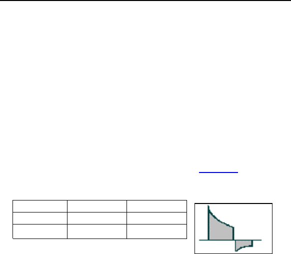
2.4.1.3 Shock Waveform
All shocks utilize a standard biphasic waveform. The waveform
starts at the calculated voltage, based on the programmed
energy level. After an exponential discharge through the lead
system to 40% of the initial charge voltage, the shock switches
polarity. At that point, it discharges to 20% of the initial charge
voltage before the w provides a
pictorial representation of the biphasic waveform.
Phase 1 Phase 2
Begin 100% 40%
End 40% 20%
Figure 2. Biphasic Waveform
2.4.1.4 Shock Energy
The Cardiac Airbag ICDs are designed to ensure that the energy
programmed for therapy is the same as what is actually
delivered to the patient regardless of the lead impedance.
2.4.1.5 Shock Polarity
The polarity of the shock therapy is non-programmable and
preset to Normal. This polarity configures the HV 1 connector
port as the negative electrode and the HV 2 connector port and
the outer housing of the ICD as the positive electrode for the first
phase of the shock.

Cardiac Airbag Technical Manual 31
2.5 Bradycardia Therapy
The Cardiac Airbag ICDs have programmable bradycardia and
post-shock bradycardia pacing functions. The post-shock
bradycardia parameters are preset to a higher rate and output
values following a delivered shock, without compromising the
who require chronic bradycardia
basic rate timer is initiated by a sensed or paced event. A
ensed event outside of the refrac
resets the lower rate timer. In the absence a
pacin will be delivered at the end of the lower rate
interva e OFF disabl dyc
tachycardia sensing and therapy may remain active.
” in its designation is a rate
functionally the same as the
ptive mode; except that the pacing
ation
Cardiac Airbag / Cardiac Airbag-T ICDs allow the selection of a
rate responsive pacing mode (VVIR). This mode allows the
ICDs bradycardia therapy function to adapt the pacing rate to
increasing or decreasing patient activity, based on data collected
from a motion sensor within the ICD. Separate criteria controls
the rate of increase and decrease of pacing, as well as the
sensitivity of the sensors.
longevity of the ICD for patients
pacing. The post-shock values are presented in the following
subsections after the chronic bradycardia support values.
2.5.1 Bradycardia Pacing Modes
The bradycardia pacing mode may be programmed to VVI or
VVIR for bradycardia pacing support or to OFF (OVO). The
s tory period inhibits pacing and
of a sensed event,
ardia pacing; however
g pulse
l. Th mode es bra
The mode that contains an “R
adaptive mode. This mode is
corresponding non-rate ada
rate will be automatically adjusted to take into account the
current load on the patient’s heart in response to increased
physical activity.
2.5.2 Basic Rate
The basic rate is the rate at which bradycardia pacing will occur
in the absence of a patient’s intrinsic rhythm. This rate may be
individually programmed for normal bradycardia pacing.
2.5.3 Rate Adapt

32 Cardiac Airbag Technical Manual
2.5.4 Gain and Threshold
The Gain defines how much the sensor signal is amplified before
it is used by the rate adaptive algorithm. The Gain is
programmed so the maximum desired pacing rate during
exercise occurs at a maximum exertion level. The Gain is preset
to 4 when programmed to the VVIR mode.
The Sensor Threshold defines the lowest sensor output that
initiates a change in the pacing rate and all motion below this
threshold is ignored by the algorithm. The Sensor Threshold is
IR mode.
rammed to
m Sensor Rate
Regardless of the sensor output, the sensor-driven pacing rate
ammable Maximum Sensor Rate. The
preset to Mean when programmed to the VV
2.5.5 Rate Increase / Decrease
The Rate Increase and Rate Decrease parameters work
together with the Gain to determine how quickly pacing rate
increases or decreases to occur with changes in the sensor
output. A rate increase of 2 ppm per second would take 45
seconds to change from a pacing rate of 60 ppm to 150 ppm.
The Rate Increase is preset to 2 ppm/sec when prog
the VVIR mode. A rate decrease setting of 0.4 ppm per second
will take 225 seconds to decrease a pacing rate of 150 ppm to
60 ppm. The Rate Decrease is preset to 0.4 ppm/sec when
programmed to the VVIR mode.
2.5.6 Maximu
never exceeds the progr
maximum sensor rate only limits the pacing rate during sensor-
driven pacing. The Maximum Sensor Rate is programmable to
either 100 or 125 ppm when programmed to the VVIR mode.
2.5.7 Pulse Amplitude
The Pulse Amplitude parameter defines the amplitude in volts of
the pacing pulses. The pulse amplitude is independently set for
normal and post-shock bradycardia pacing.

Cardiac Airbag Technical Manual 33
2.5.8 Pulse Width
The Pulse Width parameter defines the duration of the pacing
pulses. The pulse width is independently set for normal and
post-shock bradycardia pacing.
2.5.9 Noise Response
The Cardiac Airbag ICD’s response to detected noise is to
deliver asynchronous pacing in ventricular channel.
2.5.10 Post Shock Pacing
Separately, bradycardia pacing support is available with the ICD
following shock therapy delivery. After a short blanking period
ardiac Airbag-T Only)
ge of information about a
nt to the physician. Home
if
function can be used for the
entire operational life of the implant (prior to ERI) or for shorter
OTE
When ERI mode is reached, this status is transmitted.
Further measurements and transmissions of Home
Monitoring data are no longer possible.
(1 second), the ICD will begin bradycardia therapy at the post
shock pacing rate, amplitude, and pulse width for the post shock
duration.
If bradycardia pacing is still required after the post shock
duration expires, standard bradycardia pacing parameters will be
utilized.
2.6 Special Features
2.6.1 Home Monitoring (C
Home Monitoring enables the exchan
patient’s cardiac status from the impla
Monitoring can be used to provide the physician with advance
reports from the implant and process them into graphs and
tables. This information helps the physician optimize the therapy
process, as it allows the patient to be scheduled for additional
clinical appointments between regular follow-up visits
necessary.
The implant’s Home Monitoring
periods, such as several weeks or months.
N :

34 Cardiac Airbag Technical Manual
2.6.1.1 Transmission of Information
sed in Section 2.6.1.4
The implant transmits information with a small transmitter, which
has a range of about 2 meters. The transmissions are activated
by the detection of an arrhythmia episode, as programmed. The
types of transmissions are discus .
implant and the patient device
must be 15 cm.
The patient device (Figure
The minimal distance between the
2.6.1.2 Patient Device
3) is designed for use in the home
device and the associated
a BIOTRONIK Service Center.
ual.
and is comprised of the mobile
charging station. The patient can carry the mobile device with
them during his or her occupational and leisure activities. The
patient device is rechargeable, allowing for an approximate
operational time of 24 hours. It receives information from the
implant and forwards it via a GSM mobile cell phone network to
For additional information about the patient device, please refer
to its man

Cardiac Airbag Technical Manual 35
Figure 3: Example of Patient Device with Charging Stand
(CardioMessenger)
io Report
The implant’s information is digitally formatted by the
BIOTRONIK Service Center and processed into a concise report
called a Cardio Report. The Cardio Report is titled depending on
the type of event transmission. This Cardio Report contains
current and previous implant data. The Cardio Report is sent to
the attending physician via fax. All reports use the same report
format.
2.6.1.4 Types of Report Transmissions
When the Home Monitoring function is activated, the
transmission of a report (Cardio Report) from the implant can be
triggered as follows:
• Event report – the ICD detects certain events, which
initiate a report
2.6.1.3 Card

36 Cardiac Airbag Technical Manual
of the patient data,
the
hourly
time interval.
Event Report events are
detected by the implant, t transmission is automatically
triggered. This is descr
a message
transmission:
•
• Detected
•
•
• Pace
• Shock
• Device st
2.6.1.5
ing
the
plant is also transmitted.
Shocks successful
• measurement
To ensure successful transmission
Cardiac Airbag-T is programmed to send up to 10
repetitive transmissions of identical data at an
- When certain cardiac and technical
a repor
ibed as an “event message”.
The following cardiac and technical events initiate
Special device status (errors)
VT
Detected and terminated VF
First ineffective shock detected
impedance < 200 Ohm or > 3 K Ohm
impedance < 25 Ohm or > 150 Ohm
atus - ERI
Description of Transmitted Data
The following data are transmitted by the Home Monitor
system, when activated. In addition to the medical data,
serial number of the im
Detection
• # of episodes in VT Monitoring Zone
• # of episodes in VF Zone
Therapy
• Shocks delivered
•
• Shocks aborted
• 1st Shock without success
Battery
• Status (i.e., OK, ERI, EOS)
Date of voltage

Cardiac Airbag Technical Manual 37
Leads
•
• nce
2.6.2 ission
The pulse generators provide real time transmission of the
unfi e EGM) to the programmer.
IEGMs SVC) and ventricle can be
sim n th of 0.5 to 200 Hz. The
IEG er via the
prog ey are then
displ kers on the
programmer screen and printed on the ECG recorder. Likewise,
ventricular paced
e the amplitudes of intracardiac signals (R-waves)
the automatic R-wave measurement function may be used.
Please refer to the appropriate technical manual for a description
of marker signal operation.
2.6 ation
Sho prolonged if the high voltage
capacitors remain uncharged for an extended period of time.
Conditioning (or reforming) the capacitors by periodically
charging them will help to ensure shorter charge times in those
hat do not regularly receive shock therapy. The ICD is
automatically re-form the capacitors every 3 months.
The p eset following an automatic
or manual capacitor reform, or any device initiated maximum
charging of the high voltage capacitors.
Pace impedance (ventricular)
Shock impeda
• Date of impedance measurements
Device Status Summary
• Status
• Remarks
Real-time IEGM Transm
lter d intracardiac electrogram (I
from the proximal shock coil (
ulta eously recorded with a bandwid
Ms may be transmitted to the programm
ramming head positioned over the ICD. Th
ayed together with the surface ECG and mar
intracardiac signals and markers identifying
and sensed events are received via the programming head, and
may be displayed on the programmer screen and printed on the
ECG recorder. IEGM markers are available for all sensed and
paced events.
To determin
.3 Capacitor Reform
ck charge times may be
patients t
preset to
ca acitor reformation clock is r

38 Cardiac Airbag Technical Manual
An automatic or manually initiated capacitor reform fully charges
the capacitors and then allows the capacitors to drain off through
the internal circuitry of the ICD. No shock will be delivered to the
pati ation process the ICD will provide
bradycardia pacing support and tachyarrhythmia sensing and
detection as programmed. If a tachyarrhythmia is detected
n, the process is aborted and therapy
is available if required.
2.6.4 Patient and Implant Data
input of data
ent. Throughout the reform
during capacitor reformatio
The Patient and Implant data screens allow
regarding the patient name, demographics, implanting physician,
date, devices implanted, location of the implant, and various
conditions related to the patient. This information is transmitted
to the ICD and resides in the device memory for later retrieval if
needed.

Cardiac Airbag Technical Manual 39
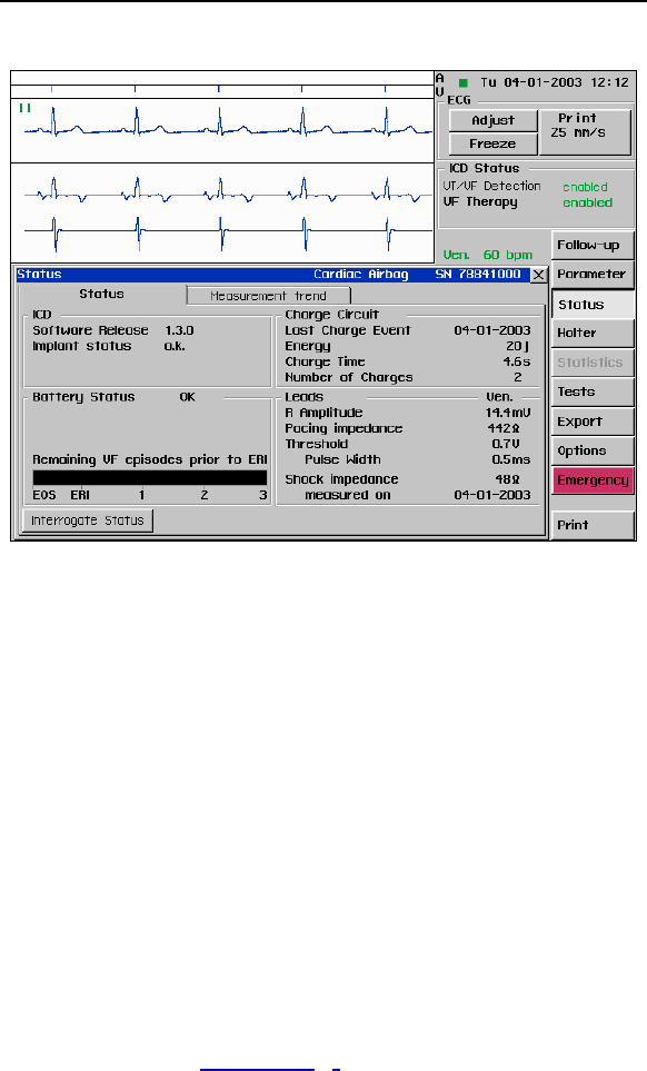
2.6.5 System Status
Various device parameters can be monitored through the Status
section of the programmer screen. (See Figure 4) Displayed
data includes ICD information, charge circuit parameters,
capacitor reformation data, battery status, and lead information.
The system status screen presents a large variety of information
about the Cardiac Airbag ICDs including:
• Serial number (always displayed after interrogation)
(End of Service)
• Last charge event
- Date
- Energy
- Charge time
• Total number of charges
• Last R-wave measurements
• Last pacing lead impedance (ventricle)
• Last pacing threshold measurement with pulse width
(ventricle)
• Last shock impedance measurement and date
• Software release
• Device status
• Battery status
- BOL (Begin of Life)
- ERI (Elective Replacement Indication)
- EOS
40 Cardiac Airbag Technical Manual
tem Status
mory
Imp a in the Holter memory. The
Holter m ration to provide the most
criti i
2.6.6
The D rrhythmia
epis e rrhythmia
detection and therapy parameters. This diagnostic data includes
a therapy history and stored intracardiac electrograms.
Episode Details - Detailed information about each individual
episode is presented as a table of events with the most recent
episode listed first. Each IEGM segment can be viewed from the
episode detail sub-menu by selecting the EGM button. From this
screen, an IEGM can be expanded and scrolled to assist in a
more accurate IEGM interpretation and a closer examination of
specific segments. (See Figure
Figure 4. Sys
2.6.6 Holter Me
ort nt information is available with
emory has a preset configu
cal nformation to the physician.
.1 Episode List
IC stores essential diagnostic data about tachya
od s that may be used to optimize tachya
5)

Cardiac Airbag Technical Manual 41
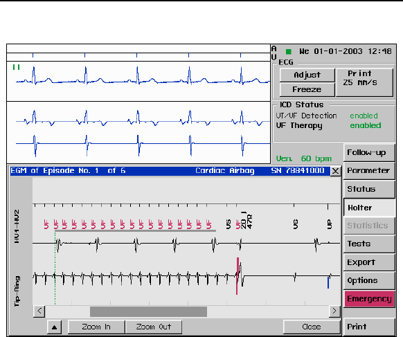
Stored IEGM - The ICD can store up to 30 minutes of two
ams (IEGMs) including the history
events:
• Terminations
py
Figure 5. Episode List
channel intracardiac electrogr
and prehistory of the following
• Detection
• Redetection
• Delivered Shocks
The ICD can store IEGMs for the following events prior to ERI:
• 3 spontaneous VF episodes treated with shock therapy
• Non-sustained VF episodes without shock thera
• 10 VT monitoring zone episodes
• Induced episodes while the programmer wand is over
the implanted ICD
Following ERI declaration, no further EGMs are stored in the
ICD. However, the episode counters continue to update until
EOS is declared. (See Figure 6)
42 Cardiac Airbag Technical Manual
Figure 6. Stored IEGM
The D offers two arrhythmia induction methods
for non-invasive EP testing. These include the following:
HF Burst Induction This feature consists of a large number of
pulses delivered in rapid succession over a period of several
seconds. The frequency of the pulses and the duration of the
Sho
means aced
stim . lses
(Nu e ization interval (R-S1)
and
2.6.7 Arrhythmia Induction Features
Cardiac Airbag IC
burst are defined by the user.
ck on T induction mode allows tachyarrhythmia induction by
of a timed T wave shock delivered after a series of p
uli Energy of the T wave shock, number of pu
mb r S1) in the pulse train, synchron
the shock Coupling interval are all user programmable.

Cardiac Airbag Technical Manual 43
2.6.8 Manual Shock
The Cardiac Airbag ICD can deliver a manual shock on demand
through a programmer command in the EP test menu. To
deliver a shock, place the wand over the device and select the
Start Shock button. A confirmation menu will appear and the
shock command will be delivered upon selecting the OK button
in this screen. After each manual shock, the EP test screen will
display the shock energy, lead impedance and charge time.
2.6.9 Test Shock
The Cardiac Airbag ICD can deliver a low-energy 1 joule (R-
wave synchronous) test shock on demand through a
programmer command in the EP test menu. This shock is
designed to measure the shock impedance and test the integrity
of the shock electrodes of an implanted ICD lead.

44 Cardiac Airbag Technical Manual
3. Software Features
ical
manuals for detailed descriptions of how to operate within the
ws.
This section describes the features available with A-K00.0.U
programmer software and the procedures necessary for
interrogating and programming Cardiac Airbag ICDs. All
references to Cardiac Airbag are also applicable to the Cardiac
Airbag-T.
Please refer to the TMS 1000PLUS or EPR 1000PLUS techn
specific menus and windo
3.1 Follow-Up Assistant (FAST) Window
After interrogating the ICD, the programmer initially displays the
Follow-Up Assistant window. (See Figure 7)
The Follow-up Assistant (FAST) is a program incorporated into
e Cardiac Airbag applications for a user-defined guided
llow-up. The “guided” follow-up function was developed to allow
the user to be directed through the required program modules
with the press of a single button.
• Interrogation of the device
• Measurement of the battery status
• Interrogation of the episode counters
• Measurement of the R-wave amplitude
• Measurement of the ventricular pacing impedance
• Measurement of pacing threshold - Threshold test
screen appears and waits for the user to perform the
ventricular threshold test.
• Printing of the follow-up data, which contains the results
of the performed interrogations.
The routines are activated in the order displayed on the
programmer screen. Functions belonging to a common topic are
grouped together. Use the check boxes to control whether a
specific procedure is performed or not.
When all of the functions have been completed the system
opens the Follow-Up Assistant window displaying the measured
values (See Figure 7
th
fo
). The Printed Follow-Up report contains
the measured values listed in the completed window.

Cardiac Airbag Technical Manual 45
Figure 7. Follow-Up Assistant with measured values
3.1.1 t Follow-up
To perform an interrogation without using the Follow-Up
Assis n ate ICD. Once
interrogation is completed all current programmed parameters
are e
3.2
A general description the main function keys is presented below:
[VT
or deac y in the ICD. The user
ansmitted.
Interrogate ICD withou
ta t, select Skip Follow-Up Interrog
list d within the Parameter screen.
Main Function Keys
/VF Detection] - The VT/VF Detection key is used to activate
tivate the programmed VF therap
may select either Enable Detection or Disable Detection from the
pop-up menu. Detection is automatically enabled following
selection of the Enable Detection command. The user is required
to confirm before the Disable Detection is tr

46 Cardiac Airbag Technical Manual
[Follow-Up] - The Follow-up Assistant (FAST) is incorporated
into the programmer applications to provide a user-defined
system guided follow-up. The “guided” follow-up function was
developed to allow consistent and quick actions by the user
through a single command.
[Parameter] - The [Parameter] window serves for programming
all parameters for sensing, detection and therapies.
[Status] - The [Status] window displays information on the
interrogated ICD and the connected lead system. The window
grouped under two tabbed sections: Status and Measurement
Trend.
[Holter] - The [Holter] functions are grouped within the following
tabs: Episode List and Holter Configuration. Episode List
displays a list of all stored episodes. Holter Configuration
contains Holter configuration and a function for modifying the
date and time setting of the programmer. Holter Time Setting
clears the date and time from the implant memory and sets the
internal clock of the implant to the time of the programming
is
wing tabs:
t. Each of
computer via a serial
0 software which is not be
atient and
their physician.
Reset: To re-initialize the ICD. This feature is locked out by
code, if it is necessary to reset the ICD, please contact your
BIOTRONIK representative.
device.
[Tests] - The [Tests] are grouped within the follo
Amplitude / Impedance, Threshold, and DFT Tes
these tabs activates windows for various tests used at implant
and follow-up procedures.
[Export] - The [Export] selection is used to copy the complete
database of the implant to a separate
interface and BIOTRONIK’s CDM 300
available in the US.
[Options] - The [Options] window contains the following three
tabs:
Options: for manually reformation of the high voltage capacitors
contained within the ICD, to activate Home Monitoring, and for
programmer control functions.
Patient Data: For storing information regarding the p

Cardiac Airbag Technical Manual 47
[Emergency] - The [Emergency] function key is always present.
Activating this key produces a screen display that turns
ventricular tachyarrhythmia Detection ON and OFF, activates
emergency bradycardia pacing parameters, or activates a
programmer commanded shock.
of this key
rameter] window serves for programming parameters for
sensing, detection and therapies. All programming of detection,
[Print] - This function key appears in the lower right side of the
screen in windows with printing options. Activation
immediately prints the relevant data from the open window.
3.3 Parameter Window
The [Pa
therapies, pacing are completed from this Parameter screen
(see Figure 8). Detection and Therapy parameters are
displayed only if VT/VF Detection is enabled. In order to provide
easily understandable parameter displays, the numeric values of
the detection parameters can be shown as an Interval (ms) or as
a Rate (bpm).
Two main function keys are located at the bottom of the
parameter window regardless of the tab selected.
[Interrogate ICD] - This function key interrogates the ICD and
loads the current programmed parameters into the programmer
memory.
[Transmit] - Activation of this key transmits the displayed
parameters as a permanent program to the ICD. This key also
appears in the [Options] window as [Transmit Settings].

48 Cardiac Airbag Technical Manual
Figure 8. [Parameter] Window

Cardiac Airbag Technical Manual 49

50 Cardiac Airbag Technical Manual
4. Sterilization and Storage
The ICD is shipped in a storage box, equipped with a quality
control seal and product information label. The label contains
the model specifications, technical data, serial number, use
before date, and sterilization and storage information.
The ICD and its accessories have been sealed in a container
and gas sterilized with ethylene oxide. To ensure sterility, the
container should be checked for integrity prior to opening.

Cardiac Airbag Technical Manual 51

52 Cardiac Airbag Technical Manual
5. Implant Procedure
5.1 Implant Preparation
Prior to beginning the ICD implant procedure, ensure that all
necessary equipment is available. The implant procedure
requires the selected lead system (including sterile back-ups),
the programmer with appropriate software, and the necessary
cabling and accessories.
For TMS 1000PLUS based testing, the following cabling and
accessories are available:
PK44 - used to connect the TMS 1000PLUS to implanted lead
systems for complete testing of the lead systems during the
implant procedure. The following adapters may be necessary:
• Adapters PA-2/PA-3 - The PA-2 adapter is used to
connect IS-1 compatible leads to the PK-44 cable. The
PA-3 adapter is used to connect DF-1 compatible leads
to the PK-44 cable.
• Adapter PA-4 - used to connect the PK-44 cable to
sensing and pacing leads while the stylet is still inserted.
Perform an interrogation of the ICD. Ensure programmer
operation, nominal device parameters and battery status is
appropriate for a new Cardiac Airbag ICD. Program Detection
and Therapy to “Disabled” prior to handling the Cardiac
Airbag ICD.
Sufficient training on the device and its associated components
is required prior to implanting the ICD. For additional
information, training and training materials contact your
BIOTRONIK representative.
5.2 Lead System Evaluation
The ICD is mechanically compatible with DF-1 defibrillation lead
connectors and IS-1 sensing and pacing lead connectors. IS-1,
wherever stated in this manual, refers to the international
standard, whereby leads and pulse generators from different
manufacturers are assured a basic fit [Reference ISO
5841-3:1992]. DF-1, wherever stated in this manual, refers to
the international standard [Reference ISO 11318:1993].
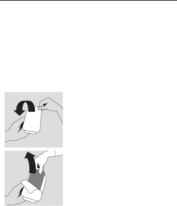
Cardiac Airbag Technical Manual 53
Refer to the appropriate lead system technical
ontai
manual.
ner
d using standard aseptic technique
5.3 Opening the Sterile C
The Cardiac Airbag ICDs are packaged in two plastic containers,
one within the other. Each is individually sealed and then
sterilized with ethylene oxide.
Due to the double packing, the outside of the inner container is
sterile and can be remove
and placed on the sterile field.
ST_01
Peel off the sealing paper of the outer
oral region. The device may be
sue or in the muscle
e etched side facing
container as indicated by the arrow.
Do not contaminate the inner tray.
Take out the inner sterile tray by
gripping the tab. Open the inner tray
by peeling the sealing paper as
indicated by the arrow.
5.4 Pocket Preparation
Using standard surgical technique, create a pocket for the
device in the patient’s pect
implanted either below the subcutaneous tis
tissue. The ICD should be implanted with th
up. The leads should be tunneled or surgically brought into the
device pocket. If lead tunneling is performed, re-evaluation of
the baseline lead signals, after tunneling is recommended.
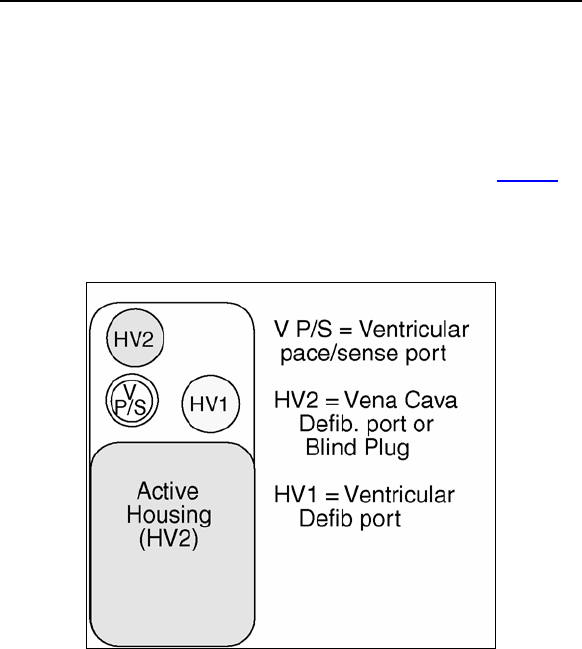
54 Cardiac Airbag Technical Manual
5.5 Lead to Device Connection
The Cardiac Airbag ICDs have been designed and are
recommended for use with a defibrillation lead systems having
one IS-1 connector for ventricular sensing and pacing and up to
two DF-1 connectors for delivery of shock therapy. Figure 9
depicts the configuration of the header ports on the Cardiac
Airbag, where HV1 and HV2 are for DF-1 connectors, and V P/S
is for IS-1 connectors.
Figure 9. Header Ports

Cardiac Airbag Technical Manual 55
Refer to the following steps when connecting
device.
the leads to the
2.
Hold the
3. the
4.
transmission is
5. wrench, the
nnection
he Cardiac Airbag ICDs come with a blind plug (pre inserted) in
an unused header port. Refer to the following steps when
connecting blind plugs to the device.
1. Confirm that the setscrews are not protruding into the
connector receptacles. To retract a setscrew, insert the
enclosed torque wrench through the perforation in the
self-sealing plug at an angle perpendicular to the lead
connector until it is firmly placed in the setscrew. Rotate
the wrench counterclockwise until the receptacle is clear
of obstruction.
Insert the lead connector into the connector port of the
ICD without bending the lead until the connector pin
becomes visible behind the setscrew.
connector in this position. If necessary, apply silicone oil
only to the o-rings on the connector (not the connector
pin).
Insert the enclosed torque wrench through
perforation in the self-sealing plug at an angle
perpendicular to the lead connector until it is firmly
placed in the setscrew.
Securely tighten the setscrew of the connector clockwise
with the torque wrench until torque
limited by the wrench.
After carefully retracting the torque
perforation will self-seal.
5.6 Blind Plug Co
T

56 Cardiac Airbag Technical Manual
1. Confirm that the setscrews are not protruding into the
connector receptacles. To retract a setscrew, insert the
2.
ctor pin becomes visible behind the
3.
4. ely tighten the setscrew of the connector clockwise
5.
5.7 P
Program ely treat the patient’s arrhythmias
and
lead system evaluation should be helpful in tailoring the various
arameters of the ICD to treat each individual patient. The
may be activated for
testing purposes once all of the lead connectors have been
The ICD may be placed in the pocket at this time. Place the
device into the pocket with the etched side facing up. Carefully
coil any excess lead length beside or above the ICD.
The pacing and sensing functions of the device should be
evaluated. It is also recommended that at least one induction
and device conversion be done prior to closing the pocket. This
will ensure that the lead system has been securely connected to
the device and has not changed position.
enclosed torque wrench through the perforation in the
self-sealing plug at an angle perpendicular to the lead
connector until it is firmly placed in the setscrew. Rotate
the wrench counterclockwise until the receptacle is clear
of obstruction.
Insert the blind plug into the connector port of the ICD
until the conne
setscrew.
Insert the enclosed torque wrench through the
perforation in the self-sealing plug at an angle
perpendicular to the connector until it is firmly placed in
the setscrew.
Secur
with the torque wrench until torque transmission is
limited by the wrench.
After carefully retracting the torque wrench, the
perforation will self-seal.
rogram the ICD
the ICD to appropriat
other therapy needs. The information obtained during the
p
detection and therapy status of the ICD
securely fastened in the device header ports.
5.8 Implant the ICD

Cardiac Airbag Technical Manual 57
Prio
should
commu
surgica
patient
retransm
Complete the Medical Device Registration Form provided with
the
5.9 Suggested Cardiac Airbag Implant
Pre-O
r to surgically closing the pocket, the telemetry contact
be evaluated to help ensure chronic programmer
nication. Close the device pocket using standard
l technique. As the final step at device implant and each
follow-up, the permanent program should be
itted to the ICD.
ICD and return it to BIOTRONIK.
Procedure
perative steps
1. Check paper supply TMS 1000PLUS or EPR 1000PLUS
. Ensure both the programmer date and time are
correct. (To change
2
the date and time, access
3 G cable and verify the signal
before the patient is prepped and draped.
More → Preferences → PC)
. Connect the PK-44 EC
4. Run a baseline ECG
5. Ensure that an external defibrillator is connected to
the patient.
Preparing the ICD
1. Select a Cardiac Airbag ICD package.
2. Place the programming wand over the ICD. A green
flashing light indicates a good telemetry
communication.
automatically interrogated with
3. Cardiac Airbag is
the wand over the ICD.
4. Press Status, (See Figure 10) located on the right
side of the screen. The button performs a complete
interrogation of the ICD.
Verify Implant Status OK.
Verify Battery Status OK.
Verify Episode Gauge is full.
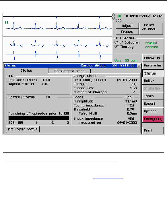
58 Cardiac Airbag Technical Manual
. System Status
Figure 10
Performing a manual capacitor reformation
2. Formation (See Figure
1. Press Options button.
Select Start 11.) and then
OK.
meter is
5. arge Time.
3. During charging, an ICD Charging
displayed in the ICD Status box.
4. Return to Status screen.
Verify the ICD Ch
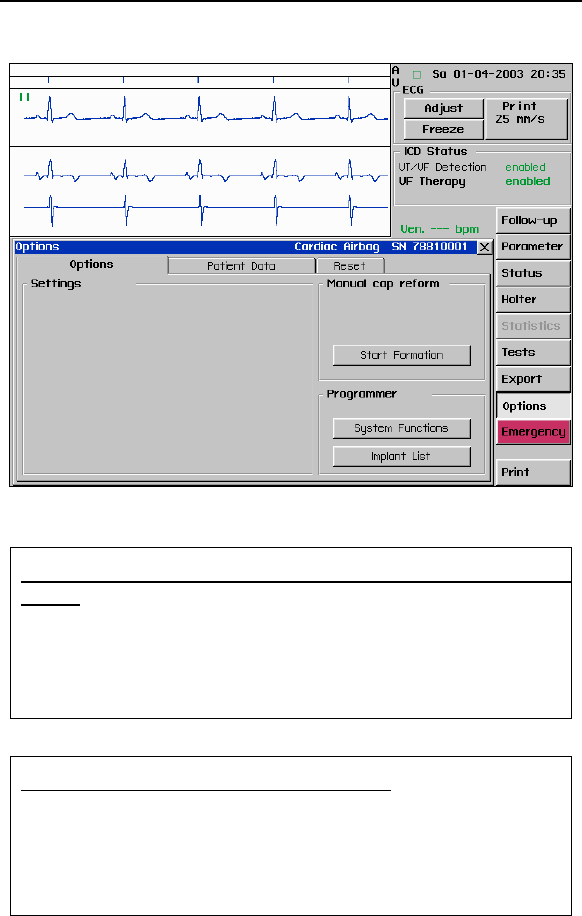
Cardiac Airbag Technical Manual 59
Figure 11. Manual Cap Reform
Acc for lead and device-basedessing the TMS 1000PLUS
ing
1. Press Options button.
2. In the Programmer area, press Implant List button
to return to the main programmer screen.
3. Select TMS 1000 from the
test
Implant List.
Connecting the ventricular lead for testing
1. Connect the terminal pins of the ventricular lead to
the appropriate port of the PK-44 Cable.
Pace/Sense pin = PA-2 block
Shock pins = PA-3 block
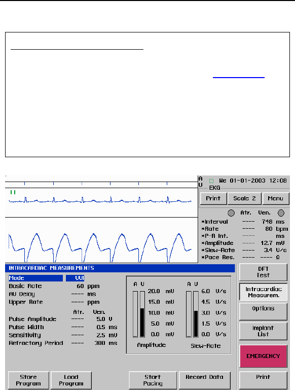
60 Cardiac Airbag Technical Manual
Measuring R-wave Amplitude
1. Select Intracardiac Measurements
2. Press and hold the Record Data (See Figure 12)
button to measure the R-wave amplitude. There is
an audible tone when the ICD has detected a
sensed R-wave.
3. In general, R-wave amplitudes should be greater
than 5 mV.
4. Press Print to obtain a printout of the measurement.
Figure 12. R-Wave Measurement

Cardiac Airbag Technical Manual 61
Determining ventricular capture
1. Verify VVI mode is highlighted.
2. Set the Lower Rate at 5 to 10 ppm above the
patient’s intrinsic rate.
Press Start Pacing to begin threshold testing at the
displayed parame
4. Decrease Pulse Amplitudes (See Figure 13) until
loss-of-capture occurs.
rhythm.
5. Press Stop Pacing to return to the patient’s intrinsic
thresholds
3.
ters.
Figure 13. Pacing Threshold Test
6. In general, ventricular pacing thresholds should be
less than 1.0 V.
7. Press Print to obtain a printout of the threshold.

62 Cardiac Airbag Technical Manual
Testing for diaphragmatic stimulation
1. Select 10.0 V in the Pulse Amplitude pop-up menu
2.
4. eturn to the patient’s intrinsic
to test for diaphragmatic stimulation.
Press Start Pacing.
3. Check for diaphragmatic stimulation.
Press Stop Pacing to r
rhythm.
Connecting the ICD to the leads
5. Verify VT/VF Detection is disabled.
6. Hand off the pre-programmed ICD to the implanting
physician.
7. Disconnect the ventricular lead pins from the PK-44
cable and insert each lead pin into the appropriate
ICD header port.
Pace/Sense pin = P/S V {IS-1}
HV 1 Shock pin = HV 1 {distal coil}
HV 2 Shock pin = HV 2 {proximal coil}
8. Tighten each set-screw using a BIOTRONIK torque
wrench until a clicking sound is heard.
9. Insert the ICD into the pocket with etching facing up.

Cardiac Airbag Technical Manual 63
Performing device-based testing measurements
to position the
.
indicates good
4. Airbag is automatically interrogated.
5. Press Start Follow-Up to automatically interrogate
the device. Battery status, sensing, lead
pisode counters are
7. ing Impedance values are within an
8.
9. test.
10. a summary of
12. ician.
1. Press Implant List button.
2. Place a sterile cover over the programming wand
and instruct the implanting physician
wand over the device
3. A green flashing light on the wand
telemetry communication
Cardiac
impedance, and e
automatically verified.
6. Check R-wave Amplitudes (greater than 5 mV).
Verify pac
acceptable range (300-1000Ω).
Verify Battery Status is OK.
Perform a
Pacing Threshold
Press Resume Follow-up to print out
these baseline measurements.
11. Enable VT/VF Detection.
Verify ICD settings with implanting phys
Performing 1 J test shock
1. Verify external defibrillation is available.
2. Verify testing sequence with implanting physician.
3. Press Tests button.
4. Select DFT Test tab.
5. Ensure wand is over the device and good telemetry
communication is established.
6. Press 1 J Test Shock and press OK to deliver a
synchronized low-energy shock (1 Joule test shock)
to confirm adequate shock coil impedance.
7. Confirm Shock Impedance values are within an
acceptable range (30-120Ω).
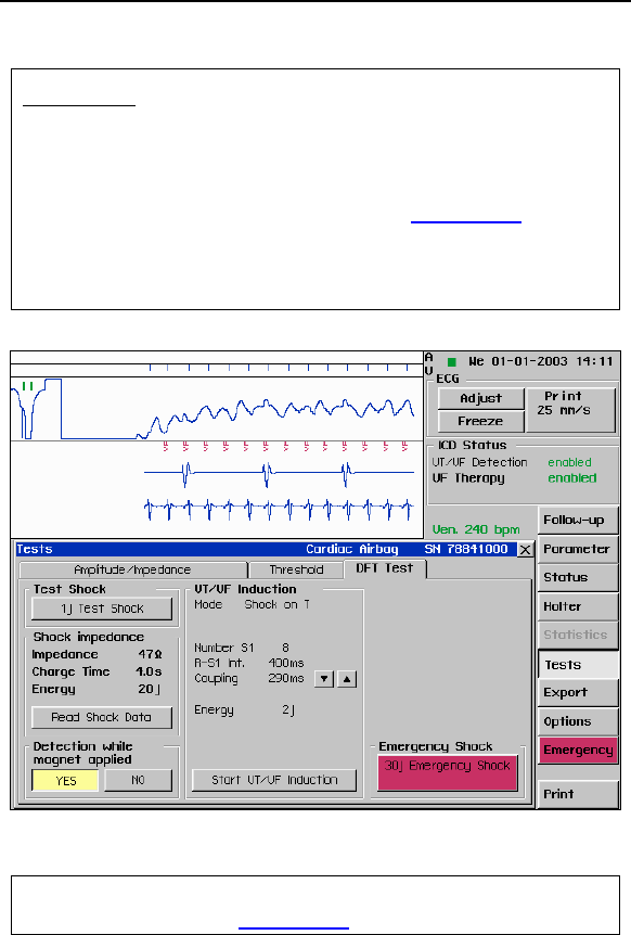
64 Cardiac Airbag Technical Manual
DFT testing
1. Select method to induce ventricular fibrillation with
the ICD: Shock on T wave or HF burst.
Press Print button to be
2. gin printing induction.
3. Press Start VT/VF Induction (See Figure 14) and
OK to induce VF.
4. Observe the IEGM, markers, and ICD charging
indicator on the programmer screen.
Figure 14. VF Induction Test
5. After successful delivery of therapy, press Print to
stop printing. (See Figure 15)

Cardiac Airbag Technical Manual 65
d prevent any inappropriate
shocks during the remainder of the implantation
Figure 15. VF Induction Test
6. Read Shock Data is automatically updated with
shock values.
7. Press Print to print out the DFT Test Screen.
8. Select Holter and review EGM to ensure proper
sensing during VF.
9. Repeat induction process for a second therapy
success or until the DFT is found.
10. After testing is complete, select VT/VF Detection to
disable detection an
procedure.

66 Cardiac Airbag Technical Manual
Final Programming
1. Verify final programming of the following
parameters: detection intervals, pacing, sensing,
and therapy.
2. Select Transmit to permanently program final
parameters.
3. Verify VT/VF Detection is Enabled.
4. Select Parameter button and press Interrogate
then Print to print out final programming and system
status.

Cardiac Airbag Technical Manual 67

68 Cardiac Airbag Technical Manual
6. Follow-up Procedures
6.1 General Considerations
An ICD follow-up serves to verify appropriate function of the ICD
system, and to optimize the programmable parameter settings.
In addition to evaluating the patient’s stored therapy history and
electrograms, acute testing of sensing and pacing is
recommended. As the final step during the patient follow-up, the
programmed parameters should be verified with the physicians
and the permanent program should be retransmitted to the ICD.
ACC/AHA/NASPE Guidelines recommend the physician perform
a patient follow-up visit every 3 months.
6.2 Suggested Cardiac Airbag Follow-Up
Procedure
Setting up the programmer
1. Turn power ON.
2. Ensure the programmer date and time are correct.
3. To change the date and time, access
More → Preferences → PC from the implant screen
4. Connect the patient to the surface ECG cable.
5. Place the programming wand over the ICD. A green
flashing light indicates a good telemetry
communication.
6. The Cardiac Airbag is automatically interrogated
with the wand over the ICD.
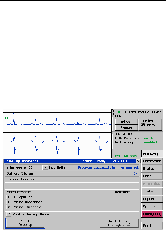
Cardiac Airbag Technical Manual 69
Starting Follow-Up Assistant
1. The software begins by displaying the Follow-Up
Assistant screen. (See Figure 16) (To fully activate
the Follow-Up Assistant program, ensure that all
boxes are checked.)
2. Press Start Follow-Up, located in the lower left
corner of the screen. This button begins the follow-
up procedure by performing a complete interrogation
of the ICD. Battery status, sensing, lead
impedance, and episode counters are
automatically verified.
Figure 16. Follow-up Assistant

70 Cardiac Airbag Technical Manual
Determining the ventricular pa
1. Enter Tests→Threshold (See Figure 17)
(automatic through Follow-up Assistant.)
Set Rate at 5 to 10 ppm above the patient’s intrinsic
rate.
2.
4.
5. litudes until loss-of-capture
occurs.
3. If desired, turn Print Test ON to run paper during
testing.
Press Start Test to begin threshold testing at
displayed parameters.
Decrease Test Amp
cing threshold
6. Press Stop Test. (Permanently programmed pacing
values are immediately restored.)
7. Select the threshold value from the pop-up menu
and press OK.
8. Select Resume Follow-up to return to the Follow-
up Assistant screen.
9. A Follow-up Report will be printed automatically.

Cardiac Airbag Technical Manual 71
Figure 17. Pacing Threshold Test
Printing and analyzing detailed Holter data information
1. Press the Holter (See Figure 18) button to view
episodes.
2. From the Episode List, select the episode EGM you
wish to view and/or print.
3. Press Print to obtain a printed record of all events
since implantation.
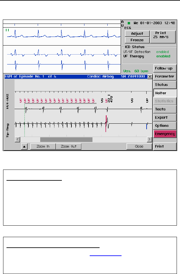
72 Cardiac Airbag Technical Manual
Figure 18. Holter EGM Episode
Verify system status
1. Press Follow-up button.
2. mplitudes (greater than 5 mV)
00Ω)
Check R A
3. Verify Pacing Impedance values are within an
acceptable range (300-10
4. Verify Battery Status is OK.
Verifying remaining shocks to ERI
1. Press Status button. (See Figure 19)
2. Review the date of last charge event, charge
time, delivered energy, and shock impedance.

Cardiac Airbag Technical Manual 73
Figure 19. System Status
3. Verify remaining shocks to ERI by checking the level
des have
of the episode gauge.
4. ERI is reached when 3 treated VF episo
occurred.
5. At ERI, contact your local BIOTRONIK
representative.
Making parameter changes and obtaining final printouts
changed and select the
3. Interrogate the device and print final summary by
selecting the Print button from the Follow-Up
screen.
1. Touch the parameter to be
new value from the pop-up menu.
2. Permanently program any changes by pressing
Transmit.

74 Cardiac Airbag Technical Manual
6.3 Longevity
The service time of an ICD can vary based on several factors,
including the number of charge sequences, programmed
parameters, number of tachyarrhythmias detected, relative
amount of bradycardia pacing required, pacing lead impedance,
storage time, battery properties, and circuit operating
characteristics. For the Cardiac Airbag ICD, there are two
methods for reaching ERI. One method is standard battery
depletion over the life of the time with no delivered therapies and
the other method is based on the number of treated VF
episodes. Both methods are described in detail below.
Service time is the time from beginning of service (BOS) to the
elective replacement indication (ERI). To assist the physician in
determining the optimum time for ICD replacement, a
replacement indicator is provided that notifies the user that
replacement within a certain period of time is required. Upon
reaching ERI, the battery has enough energy left to continue
monitoring for at least three months along with the ability to
deliver a minimum of six high-energy shocks. Upon reaching
end of service (EOS) all tachyarrhythmia detection and therapy
disa d
6.3.1 Standard ERI Method
The servi m beginning of service (BOS) to elective
replac
is ble .
ce times fro
ement indication (ERI) are listed below in Table 4. All
assume pacing
d pulse amplitu
estimates rate of 50 ppm with a pulse width of
.5 ms an de of 2.4 volts and 500 ohm pacing
pedance and all shocks at maximum energy (30 joules) at
37C. The estimates for service time are based on a 24 month
sh prior
to the
what is de
0
im
elf life, therefore, if the Cardiac Airbag ICD is implanted
24 month period, the service time may be longer than
picted in Table 4.

Cardiac Airbag Technical Manual 75
In this table, it is assum
treat ventricular tachyar
ed that the device delivers no shocks to
rhythmias, however, automatic capacitor
reformations are equally spaced on a quarterly (every 3 months)
basis throughout the life of the ICD. Therefore, the table starts
at a minimum of 4 shocks per year, because capacitor
reformations are equivalent to shocks. The estimates associated
with 0% pacing support assume the ICD is sensing an intrinsic
sinus rhythm at a rate of 70 bpm.
Table 4: Longevity Estimates
VVI Pacing
Support
Shocks Per Year
(includes cap reforms)
Years
12 3.5
10 3.7
8 3.9
6 4.1
100 %
4 4.4
12 3.7
10 3.9
8 4.1
6 4.4
50 %
4 4.7
12 3.8
10 4.0
8 4.3
6 4.6
15 %
4 4.9
12 3.9
10 4.0
8 4.4
6 4.7
0 %
4 5.0
After the ERI period the device is at EOS (End of Service) and
requires explantation. Upon reaching EOS all tachyarrhythmia
detection and therapy is disabled.
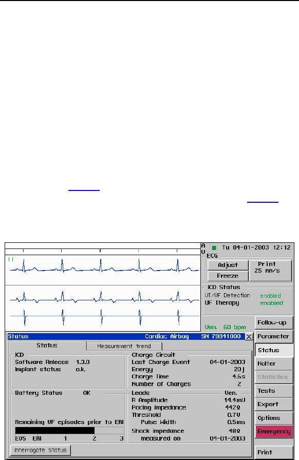
76 Cardiac Airbag Technical Manual
6.3.2 Treated VF Episode ERI Method
The Cardiac Airbag ICD is designed to treat a limited number (3)
of spontaneous VF episodes prior to reaching ERI. Induced VF
episodes via the BIOTRONIK programmer that receive shock
therapy with the programmer wand in place do not increment
against the 3 treated VF episode limit. Only spontaneous VF
episodes that receive shock therapy increment the treated VF
episode count. Any VF episode that is detected by the ICD and
the resulting charge is aborted prior to receiving a shock does
not count against the 3 treated VF episode limit.
The er screen and printouts have been designed to
display the current status of the Cardiac Airbag ICD upon
interrogation. Figure
programm
20 displays the VF treated episode Gauge
after ontaneous ther was delivered. ure
one sp apy Fig 21
displays the ERI status after the Cardiac Airbag has treated 3 VF
episodes.
Figure 20. Status Following 1 VF Episode

Cardiac Airbag Technical Manual 77
a
all
Figure 21. Status at ERI
Upon reaching ERI, the battery has enough energy left to
continue monitoring for at least three months and to deliver
minimum of six high energy shocks. The estimates associated
with duration of ERI assume the ICD is sensing an intrinsic sinus
rhythm at a rate of 70 bpm. After this period the device is at
EOS and should be explanted. Upon reaching EOS
tachyarrhythmia detection and therapy is disabled.

78 Cardiac Airbag Technical Manual
6.4 Explantation
Explanted ICDs, lead systems, and accessories may not be
reused. Please complete the appropriate out of service (OOS)
form and return it to BIOTRONIK with the explanted devices. All
explanted devices should be sent packaged in a bio-hazard
container. These may be delivered to either the local
BIOTRONIK representative or the BIOTRONIK home office for
expert disposal. Contact BIOTRONIK if you need assistance
with returning explanted devices. If possible, the explanted
devices should be cleaned with a sodium-hyperchlorine solution
of at least 1% chlorine and then washed with water prior to
shipping.
The pulse generator should be explanted before the cremation of
a deceased patient.

Cardiac Airbag Technical Manual 79

80 Cardiac Airbag Technical Manual
7. Technical Specifications
The following are the technical specifications for the Cardiac
Airbag ICDs. The ranges are presented in the format:
x…(y)…z
where x = the lowest value, y = the increment, and z = the
largest value.
NOTE:
Values depicted in gray are preset in the ICD and are not
programmable values.
Mechanical Properties
Parameter Value Range
Dimensions 67 x 55 x 13 mm
Conducting Surface Area 67 cm2
Volume 39 cc
Mass 73 g
Housing Material Titanium
Header Material Epoxy resin
Seal Plug Material Silicone
Cardiac Airbag and
Cardiac Airbag-T
Lead Ports
1 x 3.2 mm IS-1 Bipolar
2 x 3.2 mm DF-1

Cardiac Airbag Technical Manual 81
Parameters - Tachyarrhythmias
Parameter Value Range
Detection Parameters for VT Monitoring Zone
Rate (VT Monitoring) OFF; 270…(10)…600 ms
222 bpm
100…
Interval Counter: Initial
Detection
16
Interval Counter: Redetection 12
Onset 20 % (adaptive)
Stability ±24 ms (absolute)
Detection and Redetection Parameters for VF Zone
Inte OFF; 200 …(10)…400 ms
m
rval / Rate
150…300 bp
Number of X 8
Number of Y 12
Termination Detection 12 in 16
Shock Therapy
Parameter Value Range
Number of Shocks 6...(1)...8 (VF)
1st Shock Energy ules 20, 30 Jo
Further Shocks 30 Joules
Shock Waveform Biphasic
Confirmation ON
Polarity Normal
Sensing
Parameter Value Range
Sensitivity Standard
Enhanced T wave suppression
Enhanced VF sensitivity
Free (This feature is locked-out in the
US)
Minimum Threshold 0.5…(0.1)…2.5 mV

82 Cardiac Airbag Technical Manual
Bradycardia Therapy
Parameter Value Range
Mode VVI, VVIR, OVO (OFF)
Rate 30…(5)…120 ppm
Amplitude 7.5 V 0.2…(0.1)…6.2,
Pulse Width 0.5, 1.0, 1.5 ms
Maximum Sensor Rate 100, 125 ppm
Sensor Gain 4
Sensor Threshold mean
Rate Increase 2 ppm/s
Rate Decrease 0.4 ppm/s
Post-Shock Brad ycardia Therapy
Parameter Value Range
Mode VVI
Rate 70 ppm
Amplitude 7.5 V
Pulse Width 1.5 ms
Duration 30 seconds
Home Monitoring (Ca Only) rdiac Airbag-T
Parameter Value Range
Home Monitoring OFF, ON
Event Report On
Repeated Interval 60 minutes

Cardiac Airbag Technical Manual 83
Federal Communications Commission Disclosure
The Belos uipped with an RF wireless
his transmitter der the
Implant Communications S nd must
s00.150 -
4 band in the Meteoro tters and
r to communicate w Meteorological
Soration S and must accept
interference that may be caused b aids, including interference
t ired operation nsmitter shall be used only
i he FCC Rule g the Medical Implant
C Service. Analog and digital voice communications are
prohibited. Although this transmitter has been approved by the Federal
ommunications Commission, there is no guarantee that it will not
receive interfer ion from this
transmitter interference.
ID number for this device is BELOS-T.
-T ICD is eq transmitter for
communications. T
l
is authorized by rule un
95) aMedica ervice (47 CFR Part
not cause harmful interference to
06.000 MHz
tations operating in the 4
logical Aids (i.e., transmi
eceivers used eather data), the
atellite, or the Earth Expl atellite Services
y such
hat may cause undes
ith t
. This tra
n accordance w
ommunications
s governin
C
ence or that any particular transmiss
will be free from
The FCC : PG6

84 Cardiac Airbag Technical Manual

Cardiac Airbag Technical Manual 85
Appendix A
Connector Compatibility
Cardiac Airbag ICDs are indicated for use only with commercially
available BIOTRONIK bipolar ICD lead systems or other lead
systems with which it has been tested. The Cardiac Airbag
family of ICDs is mechanically compatible with:
• IS-1 sensing/pacing lead connectors
• DF-1 defibrillation lead connectors.
The Cardiac Airbag and Cardiac Airbag-T ICDs have a single
IS-1 header port and two DF-1 header ports.

Distributed by:
BIOTRONIK, Inc.
6024 Jean Road
Lake Oswego, OR 97035-5369
(800) 547-0394 (24-hour)
(503) 635-9936 (FAX)
Manufactured by:
BIOTRONIK GmbH & Co.
Woermannkehre 1
D-12359 Berlin
M4088-A 3/03 German
y