Biotronik CYLOS Cylos DR-T User Manual ENG Cylos 352923 0 102 rev 2
Biotronik, Inc. Cylos DR-T ENG Cylos 352923 0 102 rev 2
UserManual.wiki
>
Biotronik
>
CYLOS User Manual
Users Manual
Navigation menu
Upload a User Manual
Namespaces
Wiki Guide
HTML
PDF
Info
Views
User Manual
Discussion / Help
Navigation


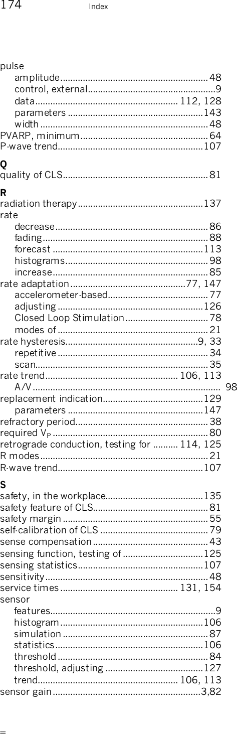
![12 Indications and Contraindications Indications and Contraindications Indications for Closed Loop Stimulation Closed Loop Stimulation uses ventricular sense (Vs) and ventricular pace (Vp) events in calculating the pacing rate. The indications for Closed Loop Stimulation are summarized in the following: — Patients with intermittent AV conduction disorders or intact AV conduction. The algorithm is based on an AV hysteresis that can be turned off for patients with high-degree AV blocks. — Patients with a permanent AV block can be paced in the ventricle with the required VP parameter set to “yes”. — Patients with vasovagal syncope can be optimally supported with the programmable “dynamic runaway protection” parameter. — Patients who would benefit from a constant AV delay are better treated when the “CLS dynamics” parameter is turned off. The following information includes general indications and contraindications for the use of cardiac pacemakers. Please refer to the appropriate medical literature for detailed information. The guidelines of the American College of Cardiology (ACC),1 the American Heart Association (AHA), and the German Society for Cardiology and Cardiovascular Research2 are particularly good sources of information. 1Guidelines for Implantation of Cardiac Pacemakers and Antiarrhythmia Devices, Gregoratos et al., ACC/AHA Task Force Report, Circulation 2002; 106: 2145-2151, October 15, 2002 2Richtlinien zur Herzschrittmachertherapie; Indikationen, Systemwahl, Nachkontrolle. [Guidelines for Cardiac Pacemaker Therapy; Indications, System Selection, Follow-up Care]. Reports by the Commission for Clinical Cardiology at the German Society for Cardiology - Cardiovascular Research] (DGK), B. Lemke, W. Fischer, H. K. Schulten, Steinkopff Verlag 1996](https://usermanual.wiki/Biotronik/CYLOS/User-Guide-564034-Page-12.png)


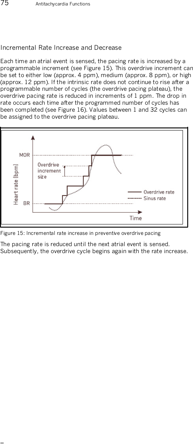
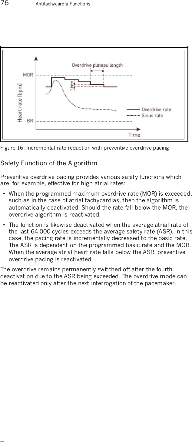
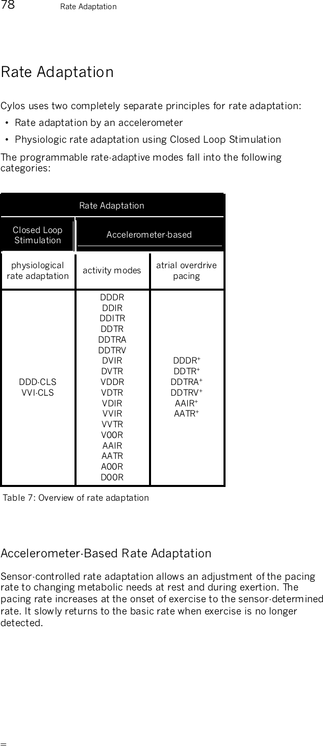
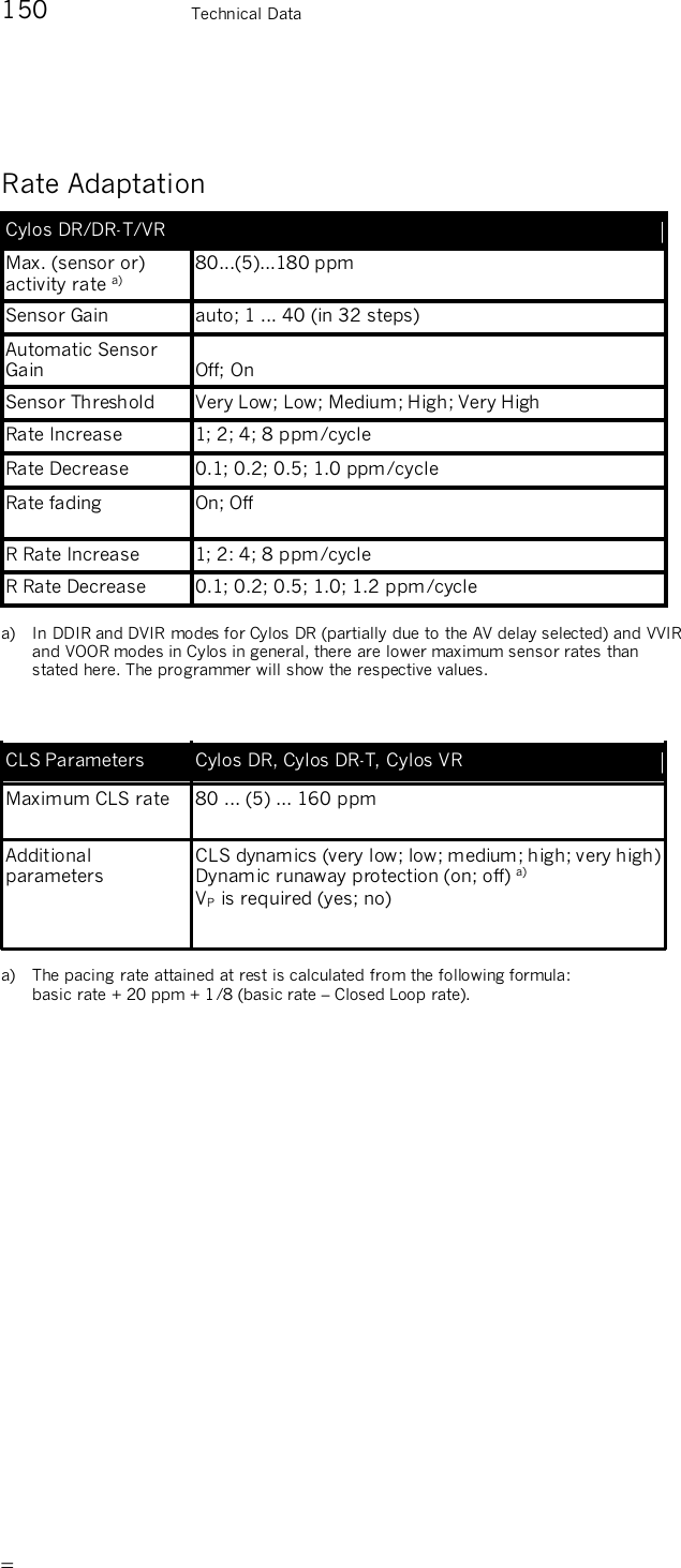
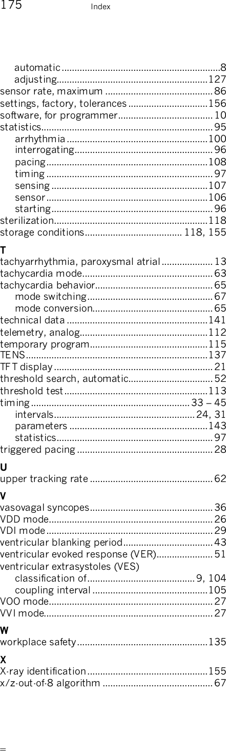
![81 Rate Adaptation Individually Adjusting CLS Parameters The following parameters can be individually adjusted with the “extended CLS settings”: • The required VP • The CLS dynamics • Dynamic runaway protection The Required VP In the DDD CLS mode, the default setting includes AV hysteresis to support existing adequate intrinsic conduction. For patients with inadequate or non-existing intrinsic conduction, it may be necessary to turn off AV hysteresis. To do this, turn on the parameter [required VP]. CLS Dynamics The factory settings for Closed Loop Stimulation provide most patients with optimum rate dynamics. Typically, there is no need to make adjustments. The rate profile resulting from Closed Loop Stimulation can vary greatly from patient to patient. In individual cases, the rate dynamics can be optimized if the rate distribution is inadequate. The [CLS Dynamics] parameter influences the pacemaker-internal target rate, which is dependent on two other pre-set parameters: the basic rate and the maximum closed loop rate. The pacemaker internally controls rate adaptation so that 20% of the pace events are always above the internal target rate. If CLS dynamics are reprogrammed to a higher value, then the rate distribution includes higher rates, and vice versa: lower programmed values yield rate distribution with lower rates.](https://usermanual.wiki/Biotronik/CYLOS/User-Guide-564034-Page-81.png)


![94 IEGM Recordings IEGM Recording during Mode Switching This type is initiated by mode switching. The parameters can only be set in the Mode Switching function. Note: Do not activate IEGM recording for high atrial rates and for mode switching at the same time. IEGM Recording during High Ventricular Rates This type is initiated by high ventricular rates and ventricular tachycardias. The following parameter triggers recording during high ventricular rates: — The ventricular detection rate determines how high a rate must be before ventricular tachycardia is considered definite and the recording is started. IEGM Recording Triggered by the Patient The patient can start the recording by placing a magnet (M50) over the implant. Note: Program the magnet effect to [synchronous] when IEGM recording should be possible by the patient. Caution! Due to the compression and reconstruction processes that the signals undergo, the IEGM recordings are not suitable for direct morphologic analyses. If you have activated the "patient-triggered IEGM recording" function, please tell the patient how to use the magnet to trigger an IEGM recording. Have the patient review the information included with the pacemaker, including the section entitled "Storing Intracardiac Data Through Magnet Application."](https://usermanual.wiki/Biotronik/CYLOS/User-Guide-564034-Page-94.png)
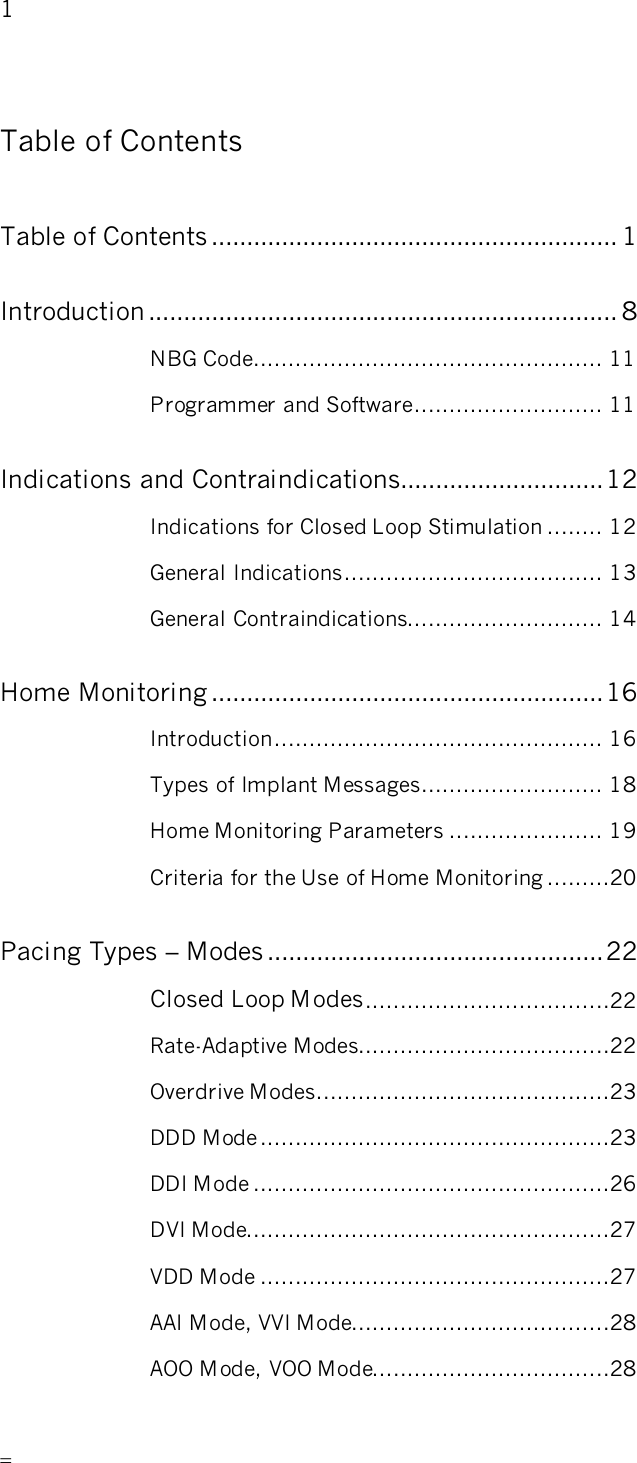
![99 Diagnostic Memory Functions (Statistics) Ventricular extrasystoles are counted both as VES as well as ventricular sense events. Special Events The following events can be recorded: — Successful AV scan hysteresis — Overdrive safety switch-off — Mode switching counter — PMT termination — VES lock-in protection Note: All event counter data are transmitted to the programmer and evaluated there, but not all events are displayed in detail on the programmer. Atrial and Ventricular Rate Histogram Dual-chamber pacemakers are equipped with a separate atrial and ventricular histogram. A bar chart displays the heart rate percentages as well as the absolute values. The number of times a heart rate occurs within certain rate ranges is recorded separately according to sensing and pacing. The rate range is divided into 16 equidistant rate classes between 40 and 180 ppm. The distribution of occurring heart rates can be displayed in a chart during follow-up. Valid for Cylos DR and Cylos DR-T A/V Rate Trend The A/V rate trend is displayed as a line chart and consists of the heart rate trend and the pacing rate trend. Both atrial as well as ventricular events are recorded at a fixed point in time. There are two available kinds of recording, a short-term trend ([12 min/fixed]) and a long-term trend ([auto/rolling]). The long-term trend begins with a resolution of 2 seconds with 120 time intervals, the time intervals are continually compressed and in the last compression level the recording takes place with a resolution of 512 seconds and 180 time intervals. Subsequently, the long-term trend is recorded in repetitive cycles. The general rule is that the shorter the recording interval, the higher the resolution. The short-term trend thus serves to create a very exact recording of short-term rate changes, for instance during an exercise test.](https://usermanual.wiki/Biotronik/CYLOS/User-Guide-564034-Page-99.png)
![107 Diagnostic Memory Functions (Statistics) Sensor Statistics The sensor statistics contain the recording of the rate trend and sensor trend. A setting of [12 min/fixed] integrates the sensor optimization. Rate / Sensor Trend The rate / sensor trend is displayed in the form of a line graph containing the length of the time intervals and the trend data. The permanent sensor parameters can be edited at the setting [12 min/fixed]. The edited sensor parameters are simulated and displayed as a trend. The thicker line corresponds to the recorded trend, and the thinner line to the simulated trend. Sensor Gain Trend The sensor gain can be recorded up to 180 days (rolling). The sensor gain is displayed on a semi-logarithmic scale from 1 to 40 with a time resolution of 2 s to 24 h, depending on the recording duration. Sensor Histogram The frequency with which the sensor rate occurs in certain rate ranges is recorded. The rate range is divided between < 40 to > 179 ppm into 16 equidistant rate classes. The graphical display shows the percentages of the individual classes in the form of a bar chart and the total number of events. The recording of the sensor rate does not depend on whether the respective pacing rate was active or whether pacing did not occur due to intrinsic events.](https://usermanual.wiki/Biotronik/CYLOS/User-Guide-564034-Page-107.png)
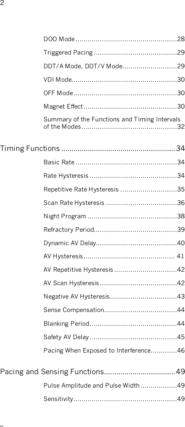
![113 Follow-up Options Note: Program the magnet effect to [synchronous] when you want the patient to do IEGM recording. Caution! Due to the compression and reconstruction processes that the signals undergo, the IEGM recordings are not suitable for direct morphologic analyses. If you have activated the "patient-triggered IEGM recording" function, please tell the patient how to use the magnet to trigger an IEGM recording. Have the patient review the information included with the pacemaker, including the section entitled "Storing Intracardiac Data Through Magnet Application." Analog Telemetry of Battery, Pulse and Lead Data The following pulse, battery, and lead data can be measured non-invasively by means of analog telemetry: Parameters Unit of Measurement Battery Voltage V Battery Impedance kz Battery Current µA Pulse Voltage V Pulse Current mA Pulse Energy µJ Pulse Charge µC Lead Impedance z Table 9: Measurable parameters of analog telemetry](https://usermanual.wiki/Biotronik/CYLOS/User-Guide-564034-Page-113.png)