Bittium Wireless DT40ISAP Integrated Service Access Point User Manual ISAP User Guide ENU
Bittium Wireless Ltd. Integrated Service Access Point ISAP User Guide ENU
Contents
- 1. 08 user guide
- 2. 08 user manual
- 3. 08 ISAP User Guide
- 4. 08 User Guide
08 User Guide
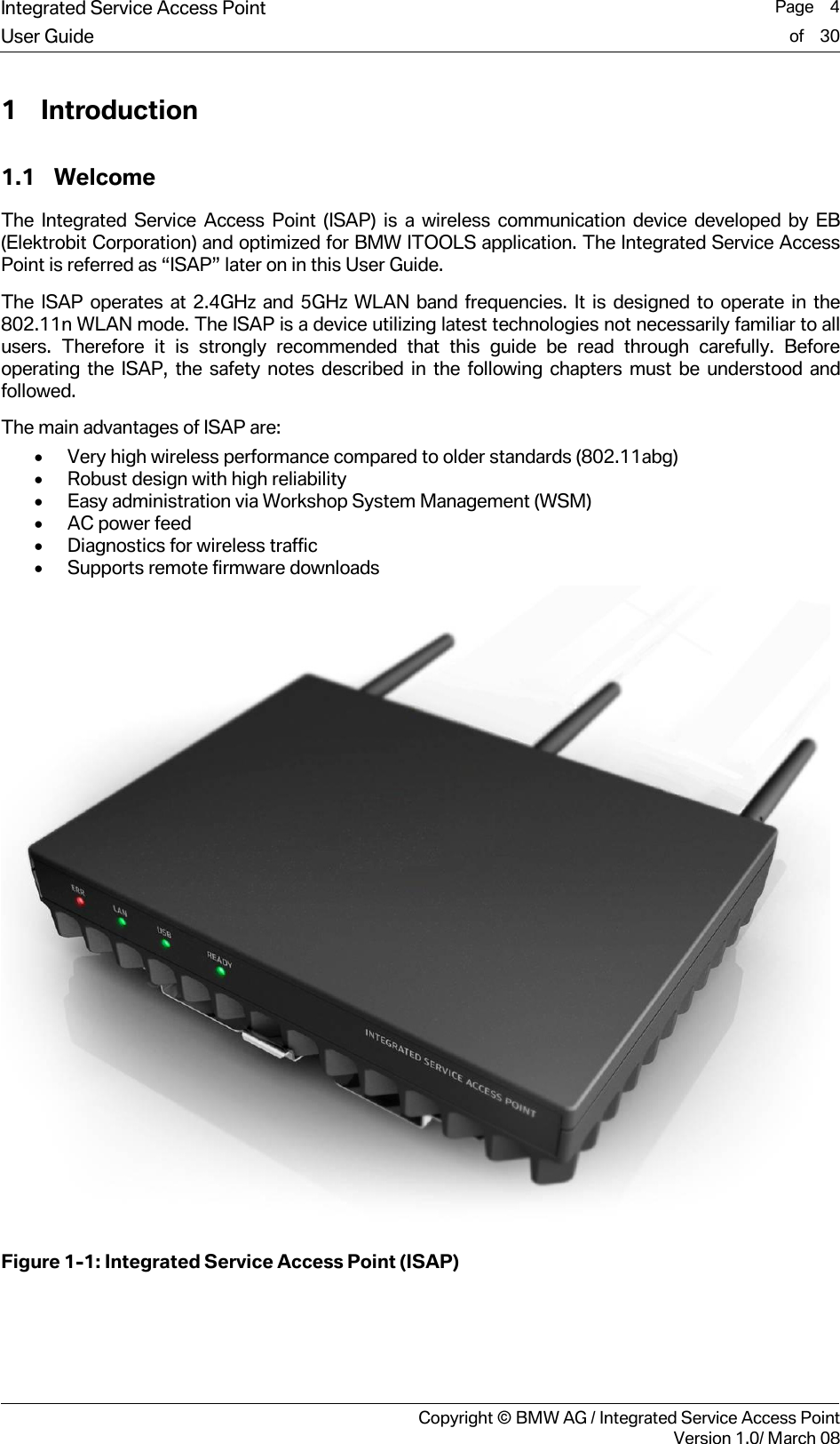
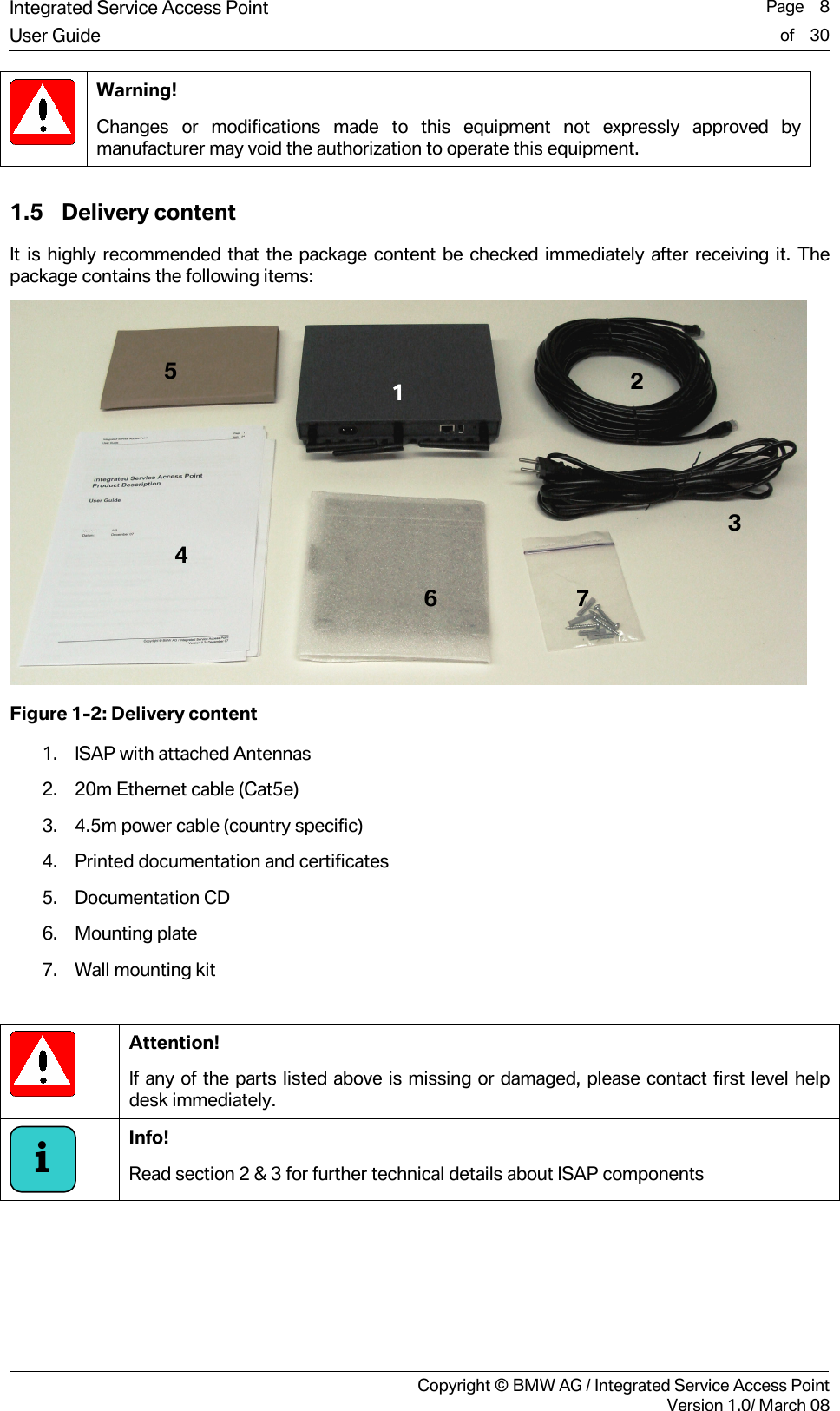
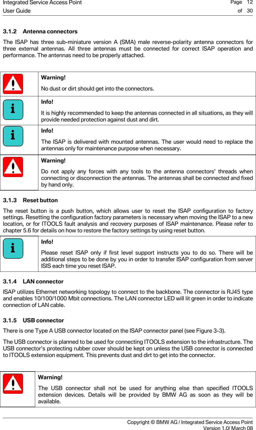
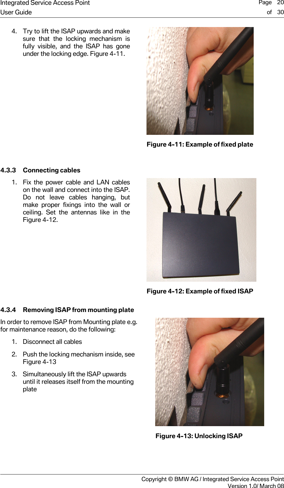
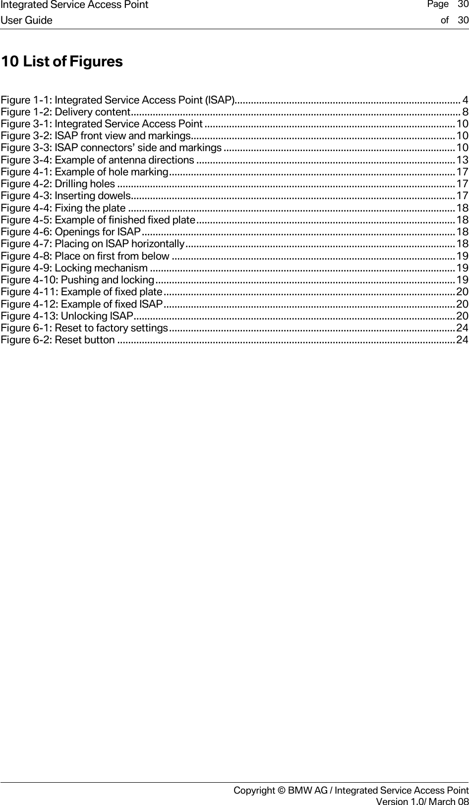
![Integrated Service Access Point Page 21User Guide of 30 Copyright © BMW AG / Integrated Service Access PointVersion 1.0/ March 08 5 Registration, Configuration and Operation 5.1 Registration of ISAP Every ISAP must be registered before the wireless operation is possible. This chapter provides an overview of ISAP registration. 5.1.1 Automatic registration Most of the workshops have live connection to BMW AG backend systems. In this normal use case, the registration of the ISAP is done automatically through Workshop System Management (WSM) within the first start-up. For further information please refer to the WSM User Guide [1]. 5.1.2 Manual registration In case the workshop does not have a live connection to the workshop database, the registration of ISAP must be done manually through a registration fax. For further information please refer to the WSM User Guide [1]. 5.2 Configuration and operation 5.2.1 Configuration The ISAP is configured through Workshop System Management (WSM) software. Please refer to the WSM User Guide [1] for details on how to configure the ISAP. 5.2.2 Channel scanning In the workshops there might be no professional site survey available during initial ITOOLS installation. Therefore the existing other WLAN band activities and users are not necessary known. In many cases this is not assumed to be a problem, as workshop is normally relatively well controlled environment. Additional to the disturbances from the workshop there can potentially be other WLAN Networks from uncontrollable environments close to the workshop, i.e. from other companies. These devices might be causing disturbances to ITOOLS Wireless Network operation. Due to these issues it is highly beneficial that ITOOLS operation is adjusted based on the environment radio operating conditions. Optimally selected radio frequency channel will improve the ITOOLS operation quality, performance, and service availability. Channel Scanning introduces a possibility to analyze the installation environment for potential problems during configuration and also later on- one of causes for problems is the use of shared radio channels, and the fact that other surrounding networks may change they operation without notifying for ITOOLS administration. For this reason ISAP is able to provide information about channel allocation. Channel Scanning can be activated through Workshop System Management (WSM), in order to get the channel scan information from ISAP. Info! In Workshop System Management (WSM) channel scanning is referred to as the Channel Wizard. It can be started via the Device Details tab in WSM. Caution! Normal operation of the ISAP is deactivated for the channel scan. i](https://usermanual.wiki/Bittium-Wireless/DT40ISAP.08-User-Guide/User-Guide-1062903-Page-21.png)
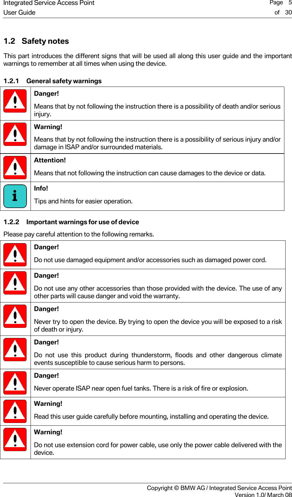
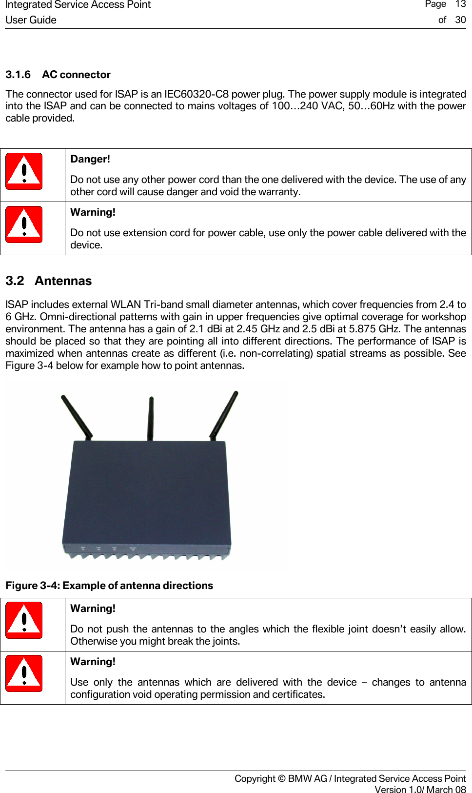
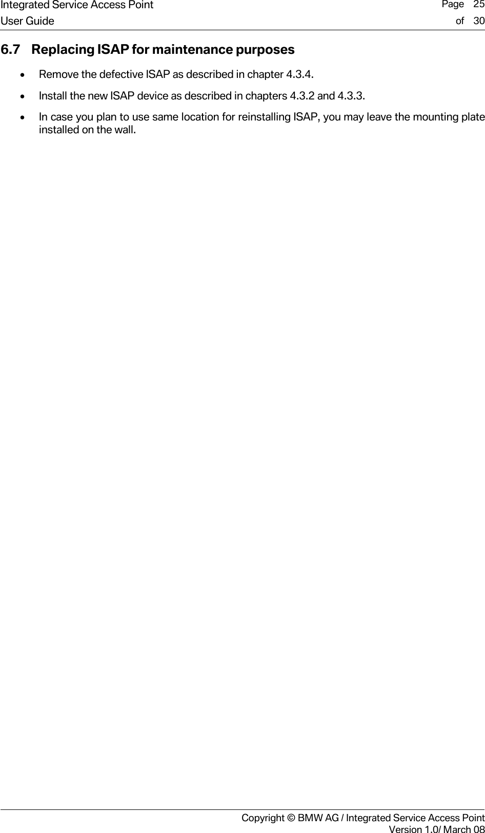
![Integrated Service Access Point Page 22User Guide of 30 Copyright © BMW AG / Integrated Service Access PointVersion 1.0/ March 08 The Channel Scan operation is based on reporting all Radio Frequency (RF) signal strength values for the least used channels, taking into account the other surrounding networks. As a result channel scan will deliver one recommended channel in 2.4 GHz band as well as one recommended channel in the 5 GHz band. It will also deliver some least used channels for each of the two bands. For more details on using channel scanning please refer to the WSM User Guide [1].](https://usermanual.wiki/Bittium-Wireless/DT40ISAP.08-User-Guide/User-Guide-1062903-Page-22.png)
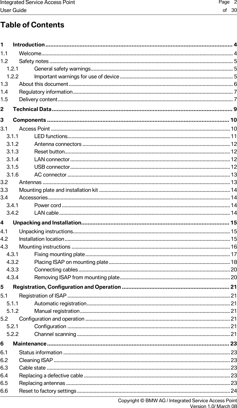
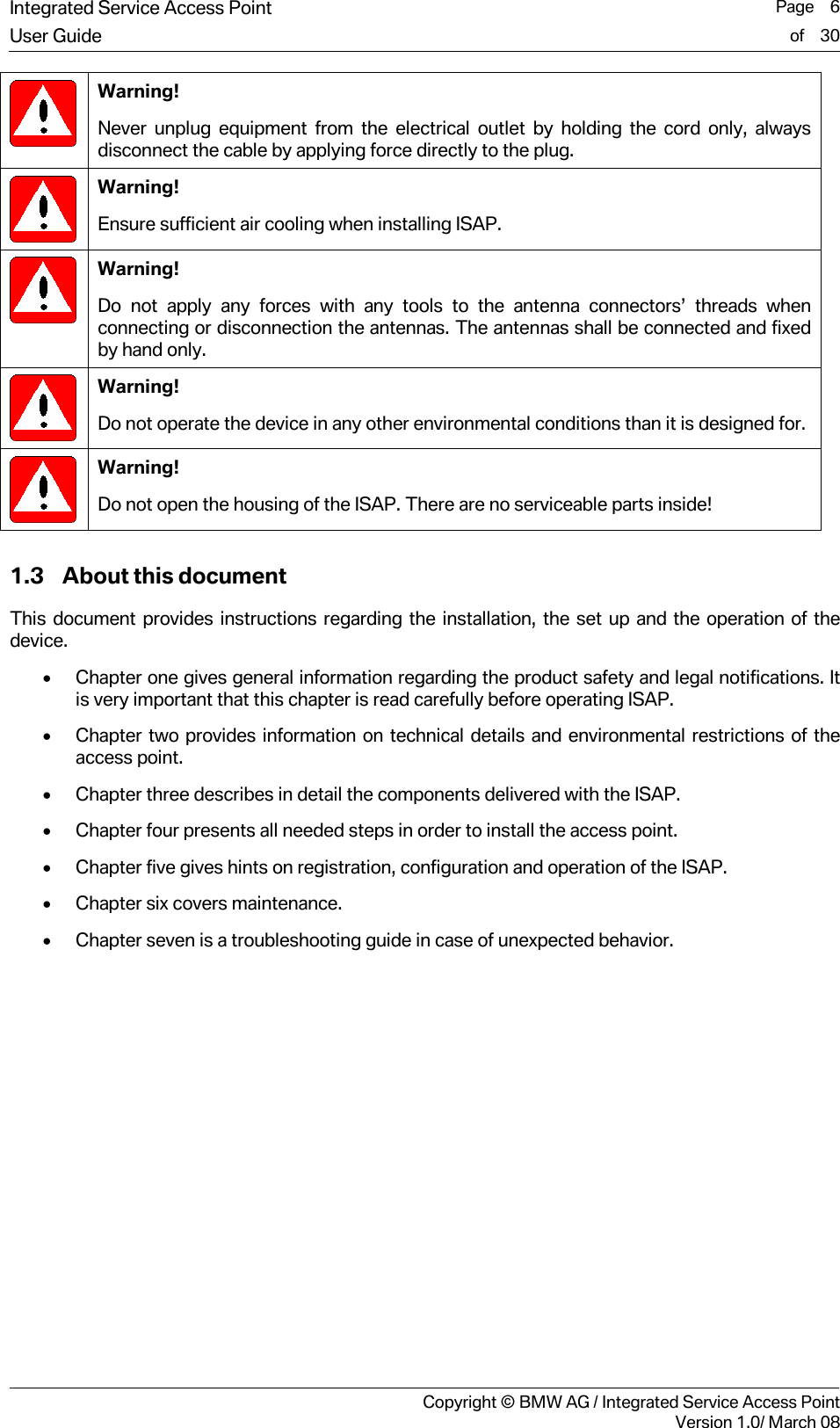
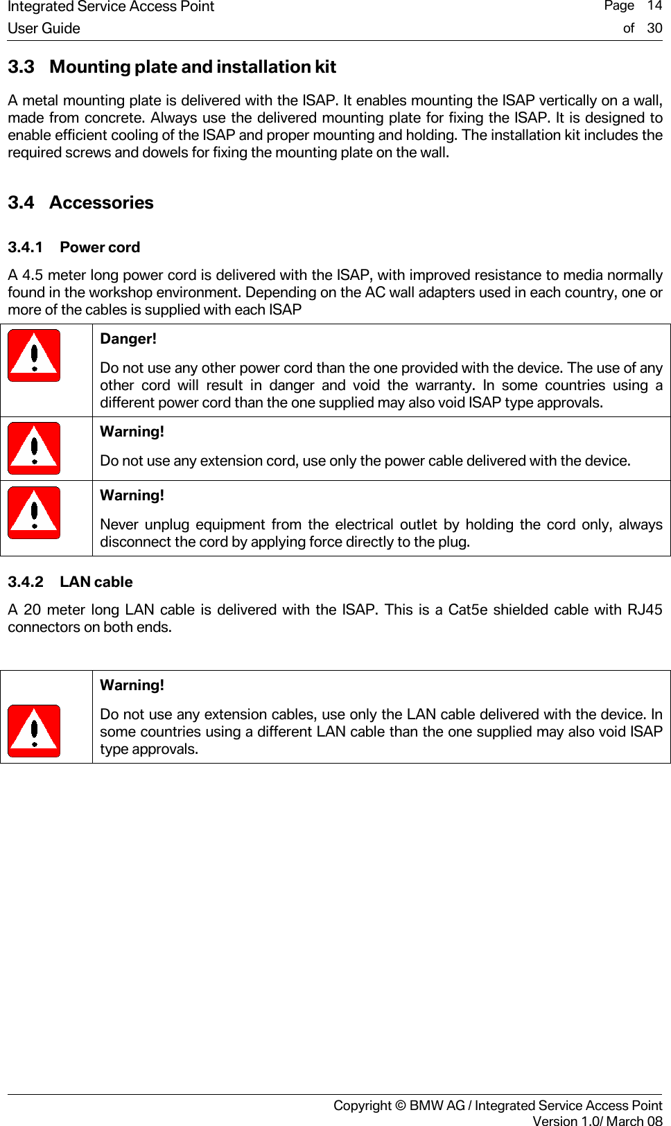
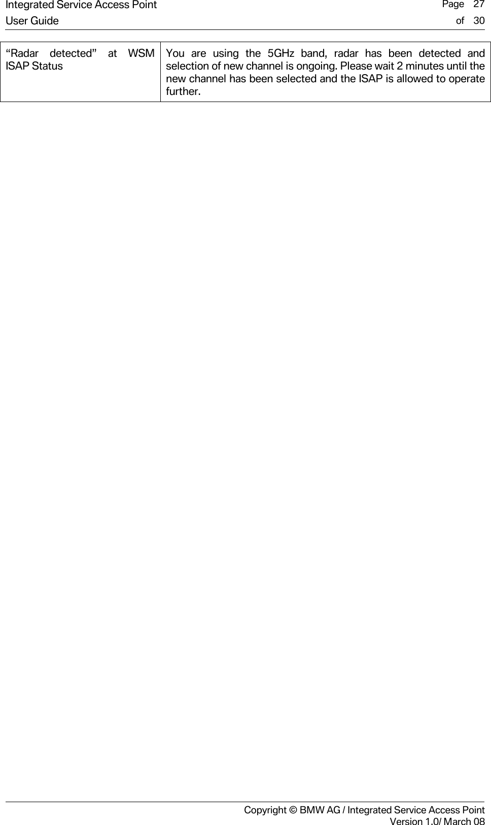
![Integrated Service Access Point Page 23User Guide of 30 Copyright © BMW AG / Integrated Service Access PointVersion 1.0/ March 08 6 Maintenance 6.1 Status information The status information of the ISAP can be seen in the Workshop System Management (WSM) graphical user interface. More information about the queries of the ISAP status is available in the WSM User Guide [1]. 6.2 Cleaning ISAP The ISAP is not designed to be in direct contact with dust, dirt or other generally harmful substances. The media found in workshops, such as oils, acids and cleaners are especially dangerous when applied directly to the ISAP. In addition, the vapors of such substances are harmful, an adequate air circulation is recommended. Due to these restrictions, it is highly recommended that the ISAP and the nearby environment of the ISAP are kept clean of substances mentioned above. Use only a moist cloth to clean the device. Do not use petroleum based substances or solvents as this may cause corrosion of the surface of the ISAP. 6.3 Cable state There are two cables delivered with the ISAP: the LAN cable and the power cable. It is recommended that the user periodically check the condition of these cables. A simple visual check is adequate. The cable shall not have any visible cut or scratches. If any damage is visible, the broken cable must be replaced with a new one. Danger! Be careful when checking the power cable. The cable must be disconnected from the power outlet prior to the checking to avoid the risk of an electric shock. 6.4 Replacing a defective cable Replacement parts can be ordered through the first level helpdesk. Disconnect the ISAP from power outlet before replacing a defective cable. 6.5 Replacing antennas The antennas might be replaced for maintenance purposes. The replacement of the antennas might be ordered through first level helpdesk. To replace an antenna, proceed with the following steps: 1. Unplug the ISAP power cable 2. Unscrew the antenna(s) 3. Attach the new antenna(s) by hand Warning! Do not use any tools when attaching or detaching antennas. Applying an excessively high momentum force may destroy the connectors. Fixing the antennas by hand is sufficient.](https://usermanual.wiki/Bittium-Wireless/DT40ISAP.08-User-Guide/User-Guide-1062903-Page-23.png)
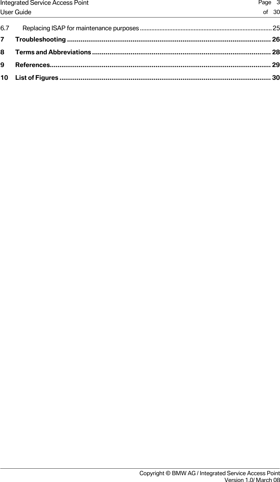
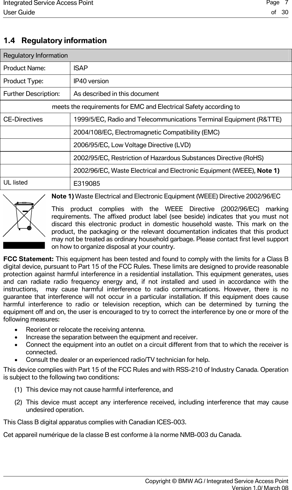
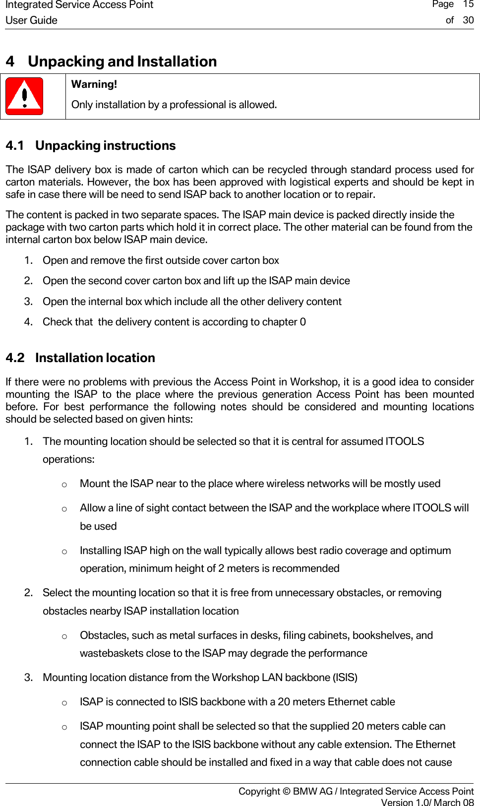
![Integrated Service Access Point Page 24User Guide of 30 Copyright © BMW AG / Integrated Service Access PointVersion 1.0/ March 08 6.6 Reset to factory settings A reset to factory settings can be issued by the user with external hardware operation as described below. The user configuration file will be overwritten with the factory default values. A new configuration with Workshop System Management (WSM) will be necessary. Please refer to the WSM User Guide [1] for more information about the configuration of ISAP. Please reset the ISAP only if first level supports tells you to do so. Figure 6-1: Reset to factory settings Figure 6-2: Reset button Follow these steps to reset the ISAP to the factory settings: 1. Preferred: unplug the power cable, wait 5 seconds, reattach the power cable. Alternative: if the ISAP is operational, push the reset button (see Figure 6-2) for at least 2 seconds, this will also reboot the ISAP. 2. Push the Reset button (see Figure 6-2) again and hold it down approximately 40 seconds until ALL the LEDs of the ISAP flash several times. 3. The flashing of all LEDs indicates that the ISAP is set back to factory settings. Release the reset button now. Info! After resetting to factory settings, the ISAP must be configured initially again through Workshop System Management (WSM). Info! In case the READY LED did not switch over to constant yellow, the reset to factory settings has failed; please try again. ii](https://usermanual.wiki/Bittium-Wireless/DT40ISAP.08-User-Guide/User-Guide-1062903-Page-24.png)
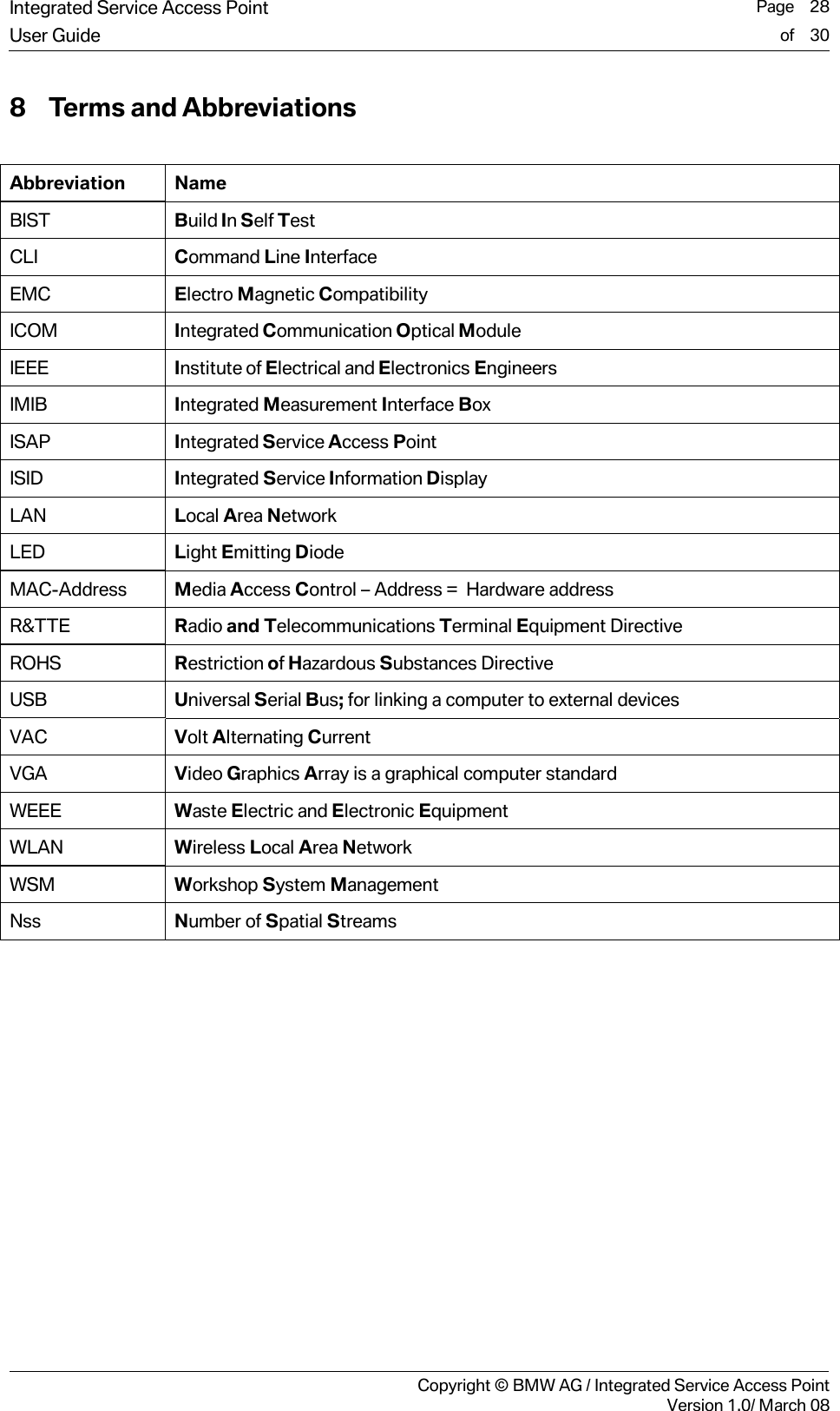
![Integrated Service Access Point Page 26User Guide of 30 Copyright © BMW AG / Integrated Service Access PointVersion 1.0/ March 08 7 Troubleshooting Warning! Do not open the housing of the ISAP. There are no serviceable parts inside! Problem description Solution Nothing happens even when the power cord is connected. Please check that the power outlet connection has 100…240VAC connected and that all fuses / circuit breakers are intact. The READY led stays YELLOW after startup for a very long time. Is the LAN led green? If not, then check the LAN cable connection. If yes, then wait 10 minutes, if READY led doesn’t start flashing or turns to green, contact first level support. Note: When started in cold temperatures, it is normal that the start-up procedure takes longer. The READY LED is flashing yellow for a very long time. There is problem with the registration process to WSM, please check the LAN connection and the check the status of WSM. The wireless network is no longer functional. Check the status of the ISAP from the WSM User Interface. Reboot the ISAP by disconnecting and reconnecting the power cord. Check the status of other ITOOLS. Is their wireless communication functional? The wireless network connection is not stable. Try and run the Channel Wizard at WSM to optimize the used channel. ERR LED is on There is a problem in ISAP, please check ISAP Status from WSM user interface, see WSM User Guide [1] READY LED is flashing green. ISAP is performing a Firmware update, do not disconnect the power because ISAP will restart itself after update is finished ISAP is not responding Please check the ISAP status from the WSM user interface, see WSM User Guide [1]. Is radar detected? If not please try rebooting the ISAP by reattaching the power cable. If the problem is not solved please contact support. “Temperature warning” at WSM ISAP Status Check operating conditions of ISAP. Make sure that the ambient temperature around ISAP is not exceeding +50 °C. Contact support if the warning doesn’t disappear. “Services not running” at WSM ISAP Status Please reboot ISAP, by re-attaching the power cable. Check that all services at WSM are running, see WSM User Guide [1]. Contact support in case the warning doesn’t disappear. “Hardware failure” at WSM ISAP Status Please contact support. “Interface problem” at WSM ISAP Status Check validity of ISAP settings in WSM user interface, see WSM User Guide [1].](https://usermanual.wiki/Bittium-Wireless/DT40ISAP.08-User-Guide/User-Guide-1062903-Page-26.png)
![Integrated Service Access Point Page 29User Guide of 30 Copyright © BMW AG / Integrated Service Access PointVersion 1.0/ March 08 9 References # "Title", Author, Place, Year [1] “WSM User Guide”, BMW, February 2008](https://usermanual.wiki/Bittium-Wireless/DT40ISAP.08-User-Guide/User-Guide-1062903-Page-29.png)