Bron Elektronik RFS2216 WIRELESS FLASH TRIGGER TRANSCEIVER User Manual
Bron Elektronik AG WIRELESS FLASH TRIGGER TRANSCEIVER Users Manual
UserManual.wiki
>
Bron Elektronik
>
RFS2216 User Manual
>
Users Manual
Contents
1.
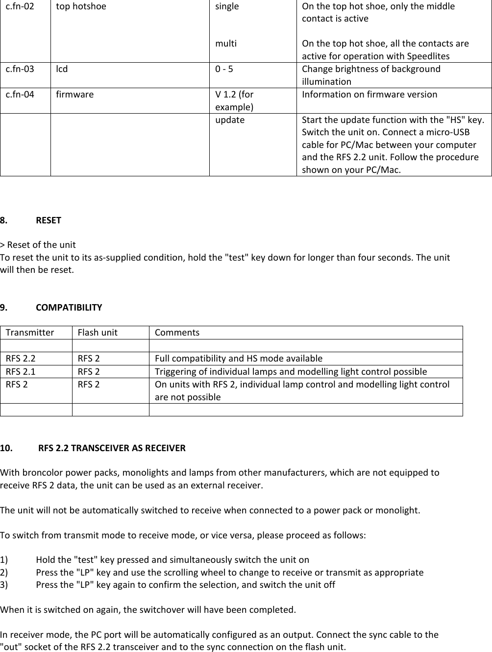
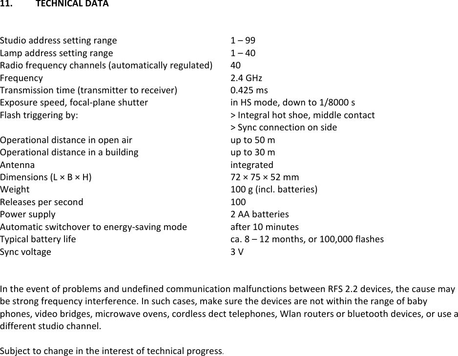
User Manual
2.
Users Manual
Users Manual
Navigation menu
Upload a User Manual
Namespaces
Wiki Guide
HTML
PDF
Info
Views
User Manual
Discussion / Help
Navigation