CHANDLER SYSTEMS LV-019 Legacy View Valve User Manual
CHANDLER SYSTEMS, INC. Legacy View Valve
UserManual.wiki
>
CHANDLER SYSTEMS
>
LV 019 User Manual
User Manual
Navigation menu
Upload a User Manual
Namespaces
Wiki Guide
HTML
PDF
Info
Views
User Manual
Discussion / Help
Navigation
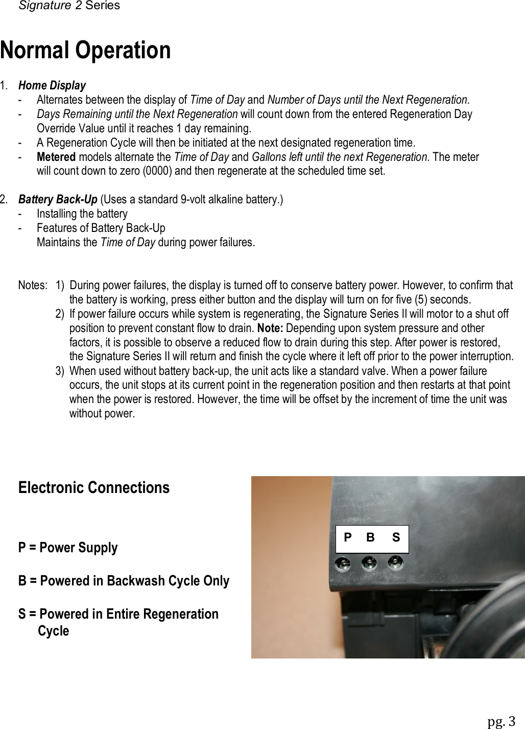
![Signature 2 Series pg. 2 : Main Menu 1. To enter Main Menu, press the Menu/Enter button. (Time of Day will flash) 2. To set the Time of Day, press the Set/Change button. (First digit will flash) Example [12:00] - To change digit value, press the Set/Change button. - To accept the digit value, press the Menu/Enter button. - Next digit will flash to begin setting. - Once the last digit display is accepted, all digits will flash. 3. To set A.M. or P.M., press the Menu/Enter button. - To change digit value, press the Set/Change button. Example [ A ] - To accept the digit value, press the Menu/Enter button. - Once A.M. or P.M. is accepted, the next menu item will flash. 4. To set the Number of Days between Regeneration or Backwash Cycles (A), press the Set/Change button. - Repeat instructions from step (2). Example [ A - 07 ] Notes: 1) Maximum value is 29. 2) If value set to 0, Automatic Regeneration will never occur. 3) Default setting is 4 days for softeners and 6 days for filters. 4) On metered models, an “H” will appear to enter Compensated Hardness in grains per gallon (gpg). Example [ H – 20] 5) Default setting is 25 gpg. 5. To set the Number of Days between Air Draw Cycles (d), press the Set/Change Button - Repeat instructions from step (2) “Used on Nitro & Nitro Pro Filters Only” Example [ d – 01 ] Notes: 1) Maximum value is 29. 2) If value set to 0, air draw is turned off, but an air cycle will still be completed when backwash cycle occurs. If the Number of Days between Air Draw Cycles is set to a higher number of days than the Number of Days between Backwash Cycles, it will have no effect. In order to turn off all cycles, both the Days between Backwash and Days between Air Draw Cycles must be set to 0. 3) Default setting is 1 day. 6. To Exit Main Menu, press the Menu/Enter button. Note: If no buttons are pressed for 60 seconds, the Main Menu will be exited automatically. SET CHANGE MENU ENTER Menu/Enter Button Set/Change Button](https://usermanual.wiki/CHANDLER-SYSTEMS/LV-019/User-Guide-2783948-Page-2.png)
![Signature 2 Series pg. 4 Starting Extra Regeneration Cycle 1. To Start Delayed Extra Cycle Example [ 1 ] - If Days Remaining Until Next Regeneration does not read ‘1’, press and hold the Set/Change button for 3 seconds until the display reads ‘1’, or ‘0000’ on metered models. - Regeneration cycle will initiate at the next designated regeneration time. 2. To start Immediate Extra Cycle First complete above step. - With Days Remaining Until Next Regeneration at ‘1’ or ‘0000’, - Press and hold the Set/Change button. - After 3 seconds, the regeneration cycle will begin. 3. To Fast Cycle thru regeneration First complete above 2 steps. Note: Fast Cycle is not necessary unless desired to manually step through each cycle step. - Press and hold the Set/Change button for 3 seconds to advance to the next cycle step. Softeners Default (min.) Filters Default (min.) Step 1 : Backwash 10 Step 1 : Backwash 10 Step 2 : Brine & Rinse 60 Step 2 : Rest 5 Step 3 : Rapid Rinse 10 Step 3 : Rapid Rinse 10 Step 4 : Brine Refill Set for full salting Step 4 : Not Used 0 Nitro Default (min.) Nitro Pro Default (min.) Step 1 : Air Release 6 Step 1 : Air Release 6 Step 2 : Backwash 10 *Step 2 : Oxyclean NP Injection 15 sec. Step 3 : Rest 5 Step 3 : Short Rinse 1 Step 4 : Air Replenish 12 Step 4 : Rest 20 Step 5 : Rapid Rinse 10 Step 5 : Backwash 10 Step 6 : Rest 5 Warning: On NITRO PRO System, if “J” Program is used, the Oxyclean NP must be used to avoid any warranty issues. Step 7 : Air Replenish 12 Step 8 : Rapid Rinse 10 Note: Depending upon system pressure and other factors, it is possible to observe flow to drain in the rest cycles. *Only if “J” program (Oxyclean NP Option) is activated.](https://usermanual.wiki/CHANDLER-SYSTEMS/LV-019/User-Guide-2783948-Page-4.png)
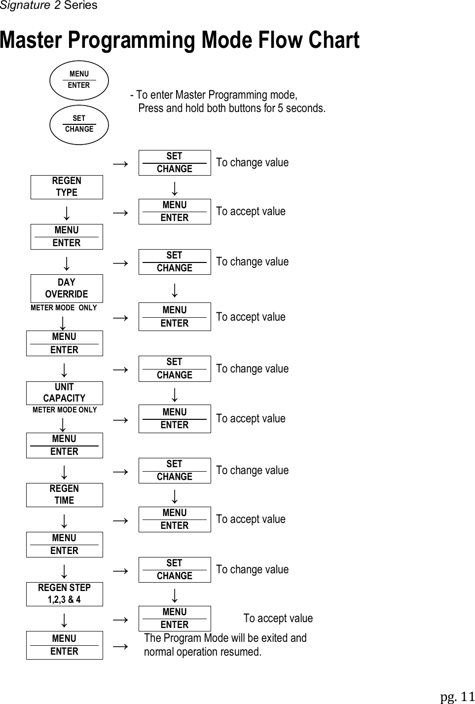
![Signature 2 Series pg. 8 Master Programming Mode To enter Master Programming Mode, press and hold both buttons for 5 seconds. Note: All Master Programming functions have been preset at the factory. Unless a change is desired, it is NOT necessary to enter Master Programming Mode. 1. Regeneration Type (t) N/A for Nitro / Nitro Pro - This display is used to set the Regeneration Type. This option setting is identified by the letter “t” in the left digit. There are two possible settings: - Timeclock / Filter Delayed – The control will determine that regeneration is required when the set regeneration time has been reached. The regeneration frequency setting will determine which days a regeneration cycle will be initiated. Example ( t - - c ). - Meter Delayed (Demand) – The control will determine that regeneration is required when the available volume of softened water drops to or below zero. Regeneration is to begin at the scheduled time set. Example ( t - - d ). ● The Set/Change button will adjust this value. To accept the digit value, press the Menu/Enter button. 2. Regeneration Day Override (A) – Meter (Demand) Mode Only – Softeners Only - Press Menu/Enter button. This display is used to set the maximum amount of time (in days) the unit can be in service without regeneration. This option setting is identified by the letter “A” in the left digit. Regeneration will begin at the scheduled time. A setting of zero will cancel this feature. - Example: Override every 7 days (A-07), default setting, or cancel setting (A-00). Maximum is 29. 3. To Set Regeneration Time ( r ) Example [ r 12A ] - The time of day at which regeneration may take place is designated by the letter “r”. - The first display digit indicates A.M. or P.M. To change the value, press the Set/Change button. - Press Menu/Enter button to accept the value and move to the next digit. - The second and third display digits indicate the hour at which the regeneration will occur. - Change the digits with the Set/Change button and accept with the Menu/Enter button. - After the entire display flashes, press the Menu/Enter button to move to the next menu item. 4. To Activate Oxyclean NP Program (Nitro Pro Only) - “J” program is selectable either off – 0 (default setting) or on – 1. - To activate the non-adjustable cycles for the Oxyclean NP, select J-1 with the Set/Change button and enter with the Menu/Enter button.](https://usermanual.wiki/CHANDLER-SYSTEMS/LV-019/User-Guide-2783948-Page-8.png)
![Signature 2 Series pg. 9 5. To Set Regeneration Cycle Step Times Softeners/Filters Only (1) (2) (3) (4) Example [ 3 – 20 ] - The next 4 displays set the duration of time in minutes for each backwash cycle step. - The step number which is currently modifiable is indicated on the far left of the display screen. - The number of minutes allotted for the selected backwash step is displayed on the far right. - Change the digit values using the Set/Change and Menu/Enter buttons as described above. 5. To Set Backwash Cycle Step Times Nitro (2) (3) (4) (5) / Nitro Pro (5) (6) (7) (8) Example [ 3 – 20 ] - The next 4 displays set the duration of time in minutes for each backwash cycle step. - The step number which is currently modifiable is indicated on the far left of the display screen. - The number of minutes allotted for the selected backwash step is displayed on the far right. - Change the digit values using the Set/Change and Menu/Enter buttons as described above. Note on Air Draw Cycle (4): Nitro Filter Only (7) Nitro Pro Only The longer the unit is set to remain in the Air Draw cycle (4), the more air is drawn into the system. A default setting of 12 minutes draws air down to the level of a normal media bed height and then returns the unit to the home display. If the system needs more air, increase the time setting for step (4) or decrease the number of days between air draw cycles. There is no way to view the number of days until the next air draw will take place. 5. System Capacity in Grains ( c ) – Meter (Demand) Only - Press the Menu/Enter button. This display is used to set the system capacity in grains and is used in conjunction with the hardness setting to calculate total gallons of treated water available between regenerations. This option is identified by the letter “c” in the left digit. The maximum value for this item is 399. Example: 32,000 grain capacity ( c 032 ). 6. To Exit the Master Programming Mode, press the Menu/Enter button until time of day returns. Note: If no buttons are pressed for 60 seconds, the Master Programming Mode will be exited automatically.](https://usermanual.wiki/CHANDLER-SYSTEMS/LV-019/User-Guide-2783948-Page-9.png)