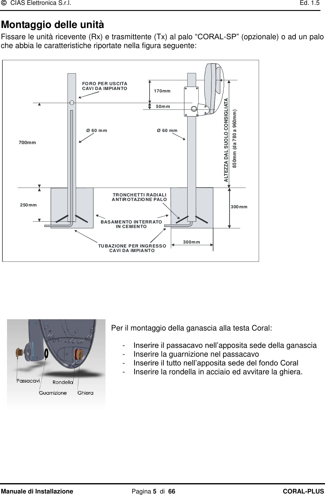
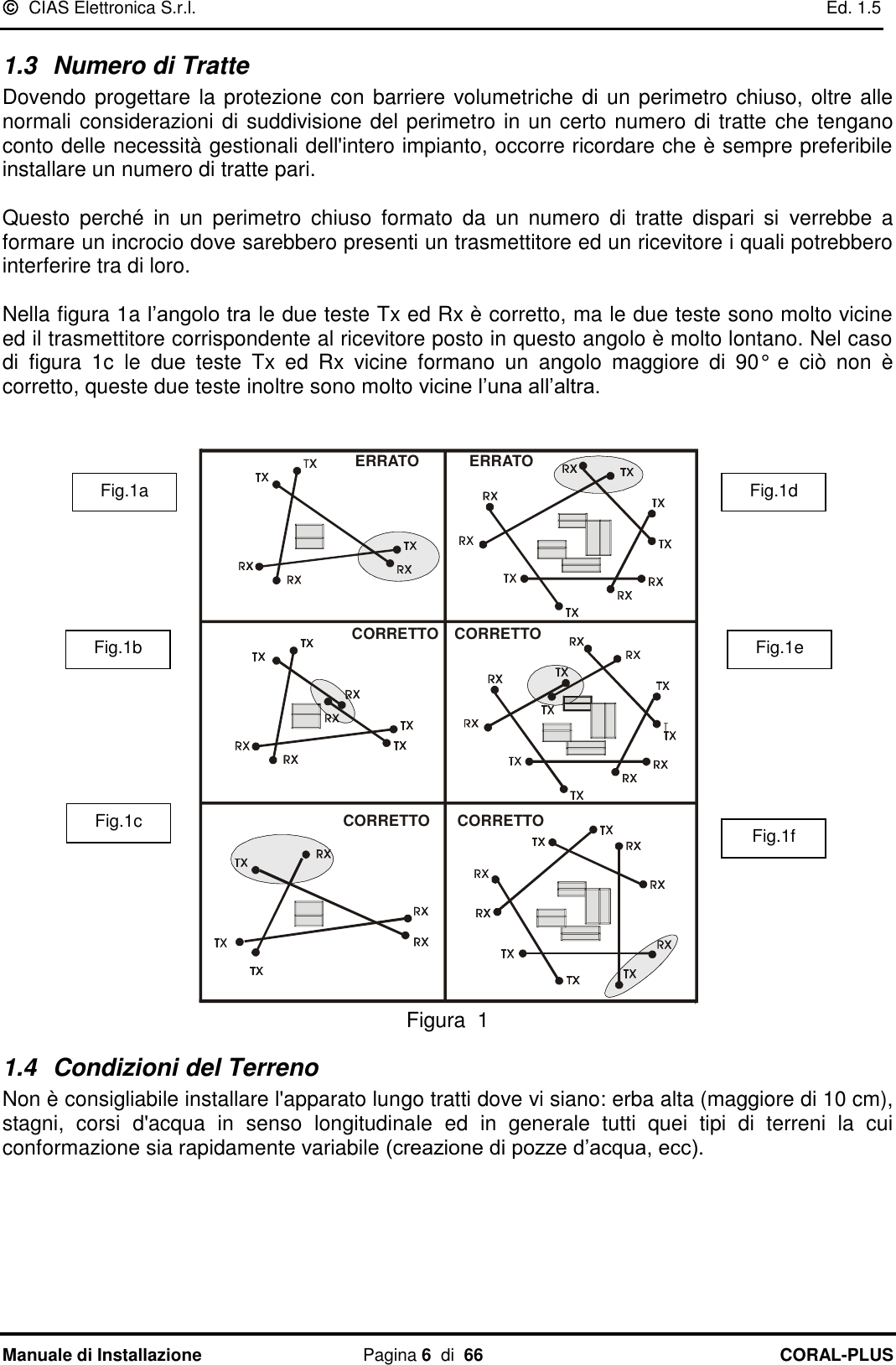
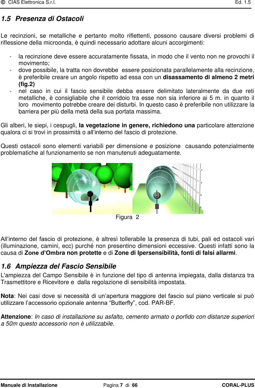
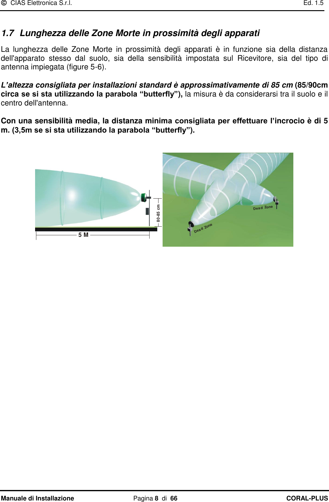
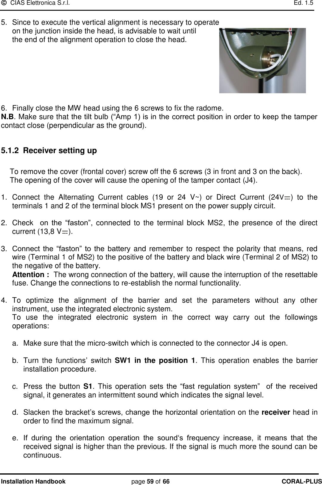
CIAS Elettronica S R L
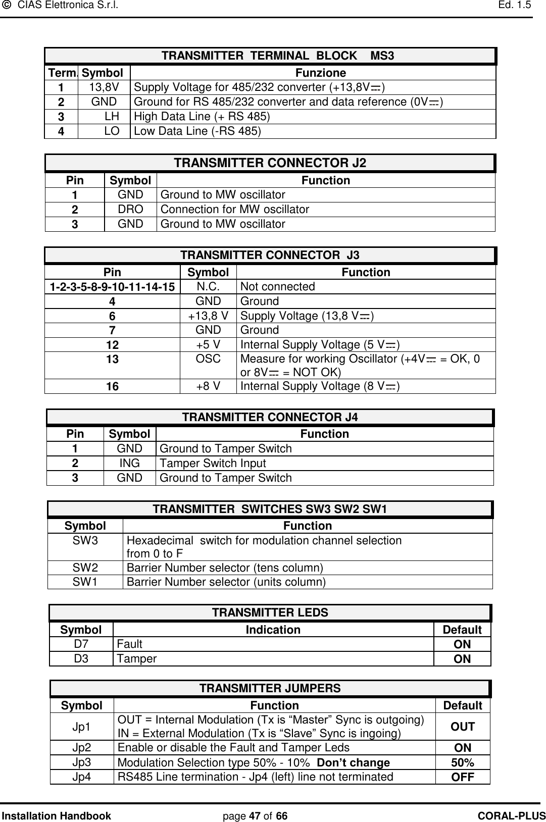
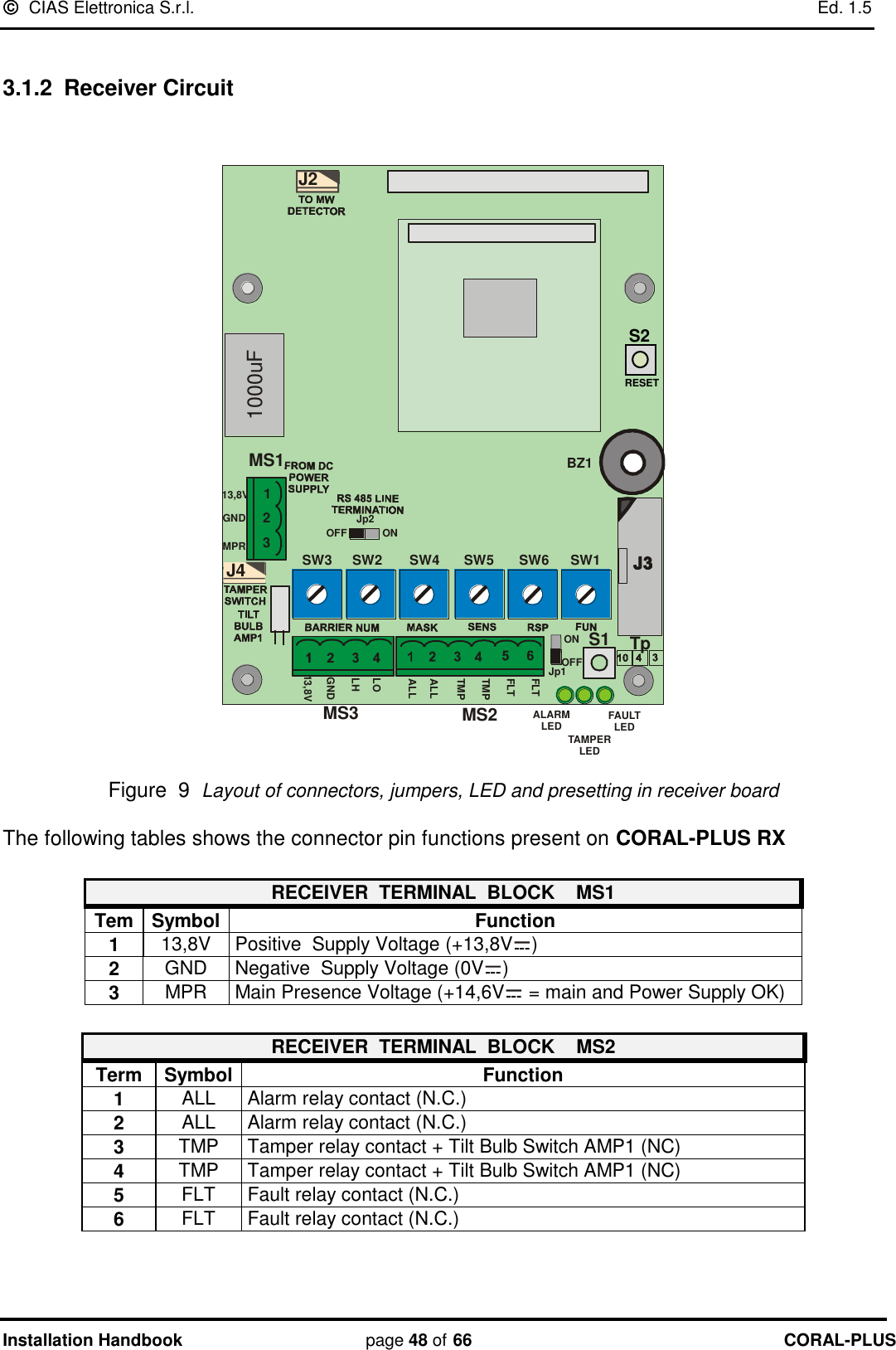
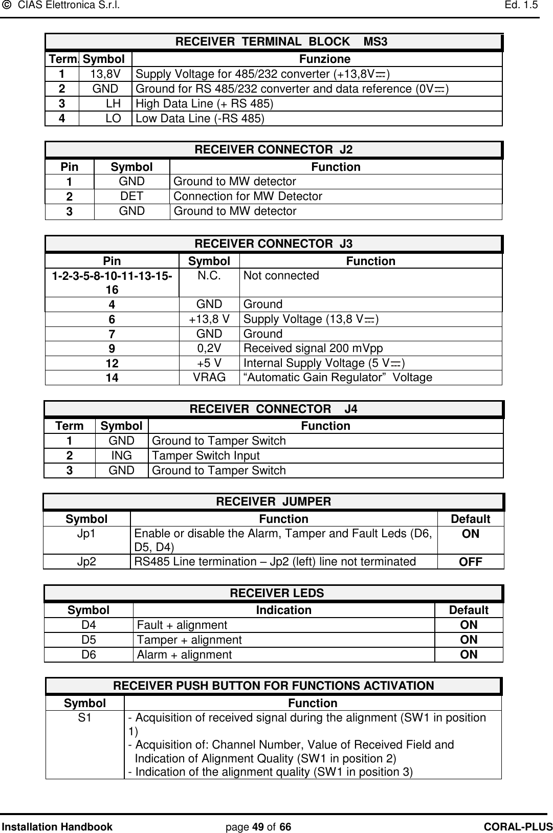
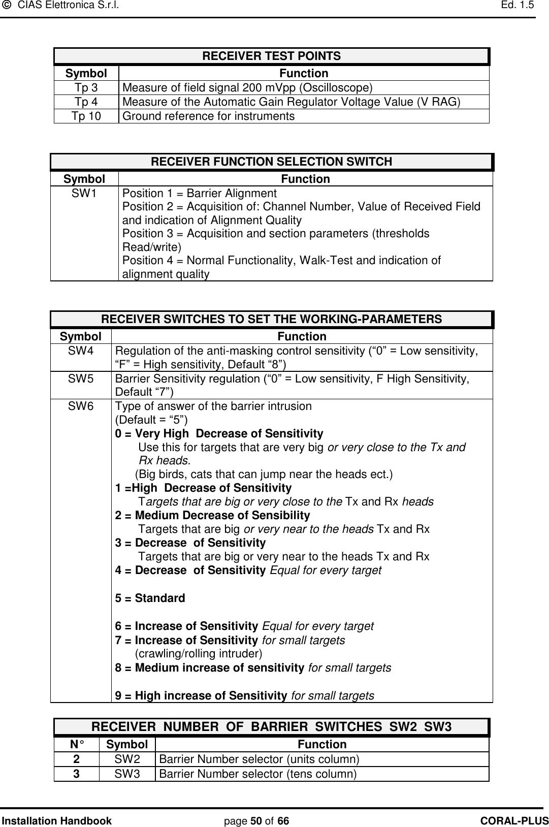
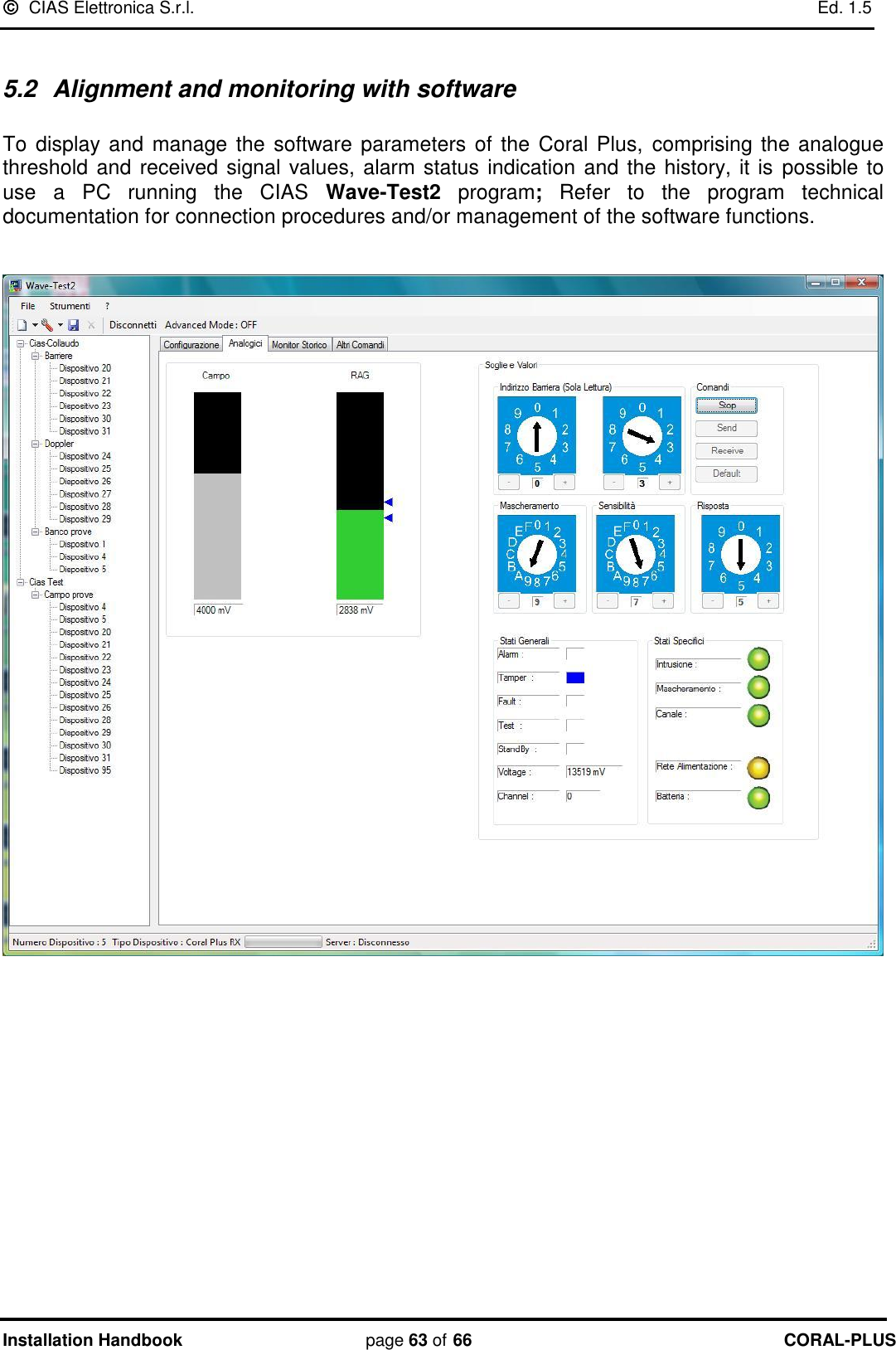
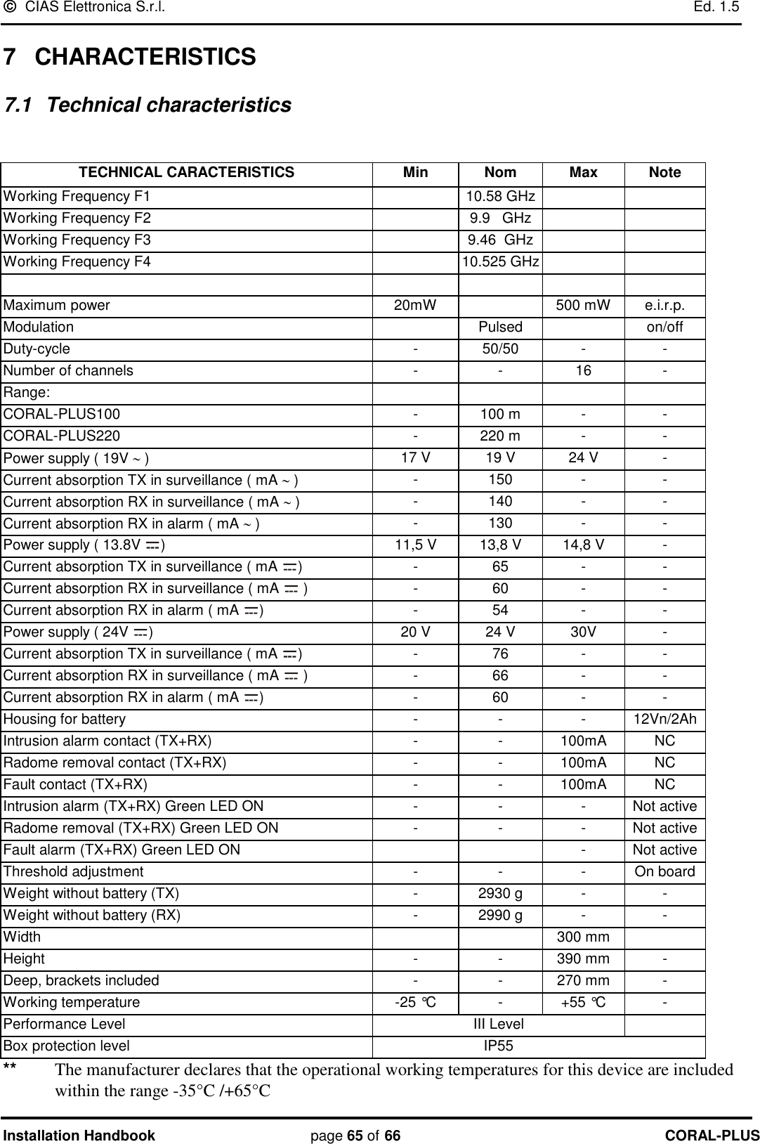
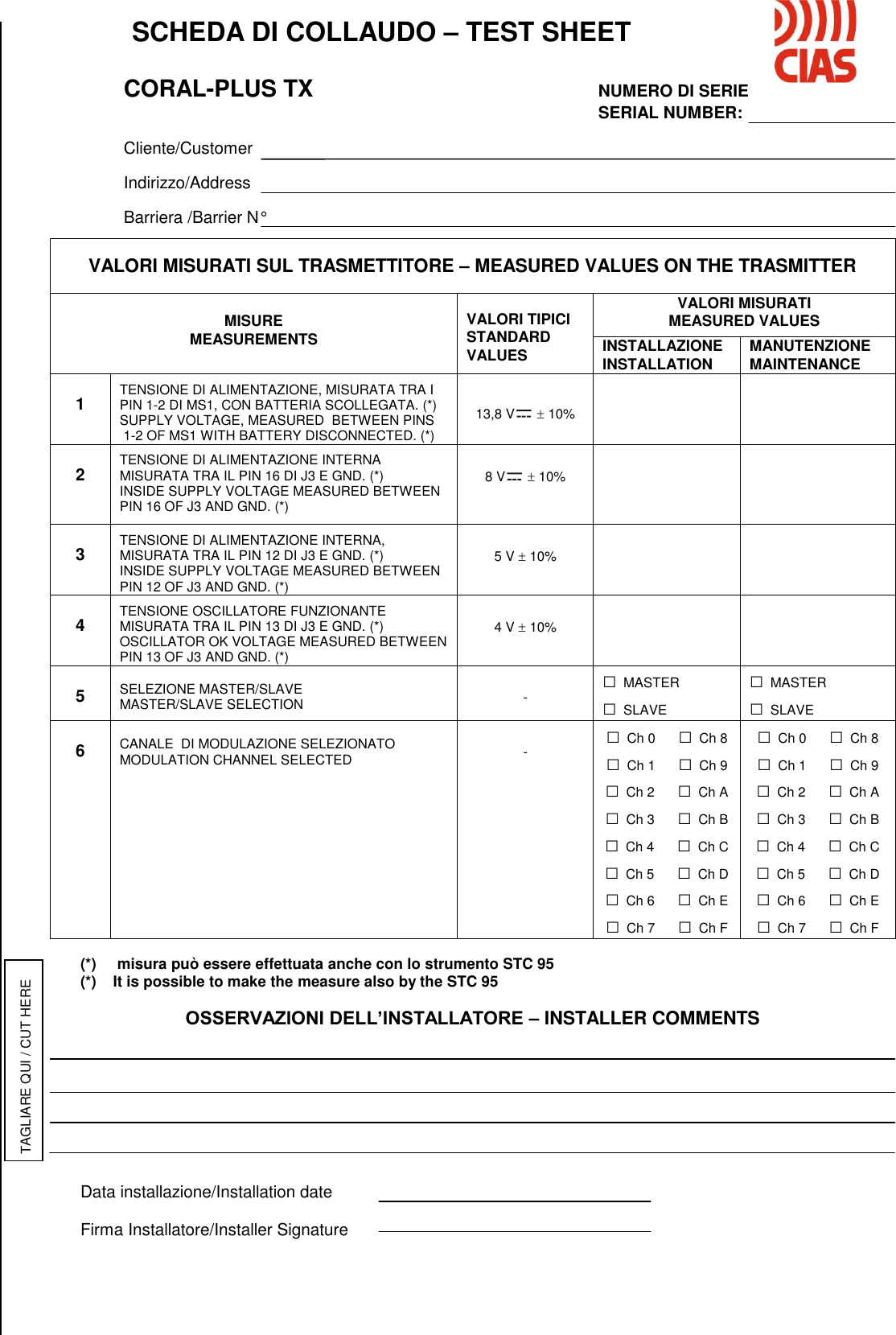
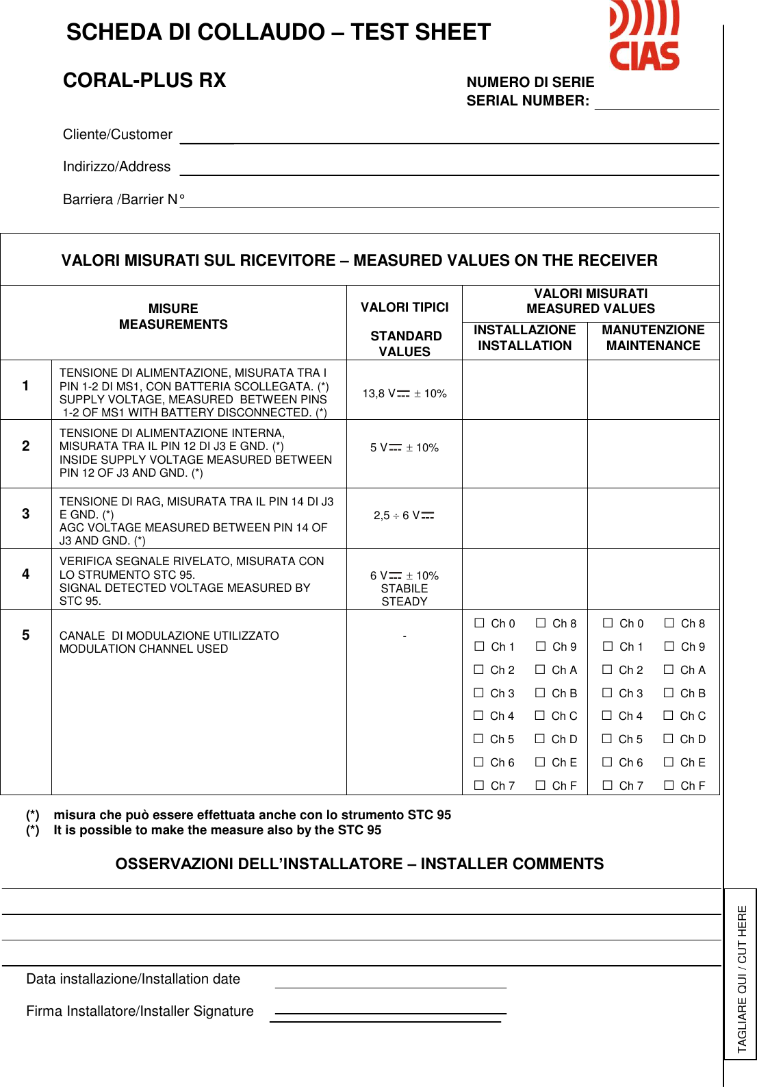
 CORAL-PLUS MICROWAVE BARRIER User Manual CORAL S

CIAS Elettronica S.R.L. MICROWAVE BARRIER CORAL S

UserManual.pdf

20MACIE0277                   CORAL-PLUS Barriera a Microonde Manuale di Installazione  Outdoor Microwave Barrier  Installation Handbook  Edizione / Edition 1.5
  CIAS Elettronica S.r.l.    Ed. 1.5 Manuale di Installazione  Pagina 1  di  66 CORAL-PLUS     INDICE  1 DESCRIZIONE ................................................................................................................................................................. 3 1.1 DESCRIZIONE .................................................................................................................................................................. 3 1.2 SCHEMA A BLOCCHI ........................................................................................................................................................ 4 MONTAGGIO DELLE UNITÀ .................................................................................................................................................. 5 1.3 NUMERO DI TRATTE ....................................................................................................................................................... 6 1.4 CONDIZIONI DEL TERRENO ............................................................................................................................................. 6 1.5 PRESENZA DI OSTACOLI .................................................................................................................................................. 7 1.6 AMPIEZZA DEL FASCIO SENSIBILE .................................................................................................................................. 7 1.7 LUNGHEZZA DELLE ZONE MORTE IN PROSSIMITÀ DEGLI APPARATI ................................................................................. 8 1.8 COME CALCOLARE LA DIMENSIONE DEL FASCIO E DELLE ZONE MORTE ........................................................................... 9 1.9 PIANO DI LAVORO DELLA MICROONDA .......................................................................................................................... 10 1.10 INSTALLAZIONE A PARETE ....................................................................................................................................... 13 2 COLLEGAMENTI ......................................................................................................................................................... 14 2.1 MORSETTIERE, CONNETTORI E FUNZIONALITÀ DEI CIRCUITI ......................................................................................... 14 2.1.1 Circuito Trasmettitore ...................................................................................................................................... 14 3.1.2 Circuito Ricevitore ........................................................................................................................................... 16 2.2 COLLEGAMENTO ALLA CENTRALE ................................................................................................................................ 19 2.2.1 Contatti di allarme: Allarme, Manomissione, Guasto ...................................................................................... 19 2.2.2 Connessioni per Sincronismo ........................................................................................................................... 20 2.2.3 Connessioni per Stand-by ................................................................................................................................. 20 2.2.4 Connessioni per Test ........................................................................................................................................ 20 2.3 LINEA SERIALE  RS-485 ............................................................................................................................................... 21 2.3.1 Interfaccia Linea Seriale RS-485 / 232 ............................................................................................................ 21 2.3.2 Connessioni per Linea Seriale RS-485 ............................................................................................................. 21 2.3.3 Configurazione Rete e Rigeneratori di segnale ................................................................................................ 21 3 ALIMENTAZIONE ........................................................................................................................................................ 23 3.1 CIRCUITO ALIMENTATORE E CARICA BATTERIA                                                    (KIT OPZIONALE COD: CORALPOWER) .. 23 3.2 ALIMENTAZIONE POE 802.3 AF                                                                       (KIT OPZIONALE COD: IP-DOORWAY) .............. 24 3.3 COLLEGAMENTO ALL’ALIMENTAZIONE 230VAC .......................................................................................................... 25 3.4 COLLEGAMENTO ALL’ALIMENTAZIONE DI RISERVA (BATTERIA) .................................................................................. 25 4 ALLINEAMENTO E VERIFICA ................................................................................................................................. 26 4.1 ALLINEAMENTO E VERIFICA ......................................................................................................................................... 26 4.1.1 Operazioni sul Trasmettitore ............................................................................................................................ 26 4.1.2 Operazioni sul Ricevitore ................................................................................................................................. 27 4.2 ALLINEAMENTO E VERIFICA CON SOFTWARE ................................................................................................................ 32 5 MANUTENZIONE E ASSISTENZA ............................................................................................................................ 33 5.1 RICERCA GUASTI .......................................................................................................................................................... 33 5.2 KIT  ASSISTENZA .......................................................................................................................................................... 33 6 CARATTERISTICHE .................................................................................................................................................... 34 6.1 CARATTERISTICHE TECNICHE ....................................................................................................................................... 34 6.2 CARATTERISTICHE  FUNZIONALI ................................................................................................................................... 35
  CIAS Elettronica S.r.l.    Ed. 1.5 Manuale di Installazione  Pagina 2  di  66 CORAL-PLUS     INDEX  1 DESCRIPTION ............................................................................................................................................................... 36 1.1 DESCRIPTION ................................................................................................................................................................ 36 1.2 BLOCK DIAGRAM ......................................................................................................................................................... 37 2 INSTALLATION ............................................................................................................................................................ 38 2.1 BARRIER ASSEMBLY ..................................................................................................................................................... 38 2.2 NUMBER OF SECTIONS .................................................................................................................................................. 39 2.3 GROUND CONDITIONS ................................................................................................................................................... 39 2.4 PRESENCE OF OBSTACLES ............................................................................................................................................ 40 2.5 AMPLITUDE OF THE SENSITIVE BEAM ........................................................................................................................... 40 2.6 LENGTH OF DEAD ZONES NEAR THE EQUIPMENT .......................................................................................................... 41 2.7 HOW TO CALCULATE THE SIZE OF THE BEAM AND DEAD ZONES .................................................................................... 41 2.8 MICROWAVE WORKING PLANE ...................................................................................................................................... 42 2.9 WALL INSTALLATION .................................................................................................................................................... 45 3 CONNECTIONS ............................................................................................................................................................. 46 3.1 TERMINAL BLOCKS, CONNECTORS AND CIRCUITS FUNCTIONS ..................................................................................... 46 3.1.1 Transmitter Circuit ........................................................................................................................................... 46 3.1.2 Receiver Circuit ................................................................................................................................................ 48 3.2 CONNECTION TO THE CONTROL PANEL ........................................................................................................................ 51 3.2.1 Alarm contacts: Alarm, Tamper, Fault............................................................................................................. 51 3.2.2 Synchronism connection ................................................................................................................................... 52 3.2.3 Stand-by connection ......................................................................................................................................... 52 3.2.4 Test connection ................................................................................................................................................. 52 3.3 SERIAL LINE RS-485 .................................................................................................................................................... 53 3.3.1 RS - 485 / 232 Network Connection Interface .................................................................................................. 53 3.3.2 RS -485 Serial Line connections ....................................................................................................................... 53 3.3.3 Network Configuration and Signal Repeaters .................................................................................................. 53 4 POWER SUPPLY ........................................................................................................................................................... 55 4.1 POWER SUPPLY AND BATTERY CHARGER CIRCUIT                                      (OPTIONAL KIT COD. CORALPOWER) ............. 55 4.2 POWER OVER ETHERNET 802.3 AF                                                           (OPTIONAL KIT COD. IP-DOORWAY) ..................... 56 4.3 CONNECTION TO THE POWER SUPPLY 230VAC ............................................................................................................. 57 4.4 CONNECTION OF STAND-BY BATTERY .......................................................................................................................... 57 5 ADJUSTMENT AND TESTING ................................................................................................................................... 58 5.1 ADJUSTMENT AND TESTING .......................................................................................................................................... 58 5.1.1 Transmitter Setting up ...................................................................................................................................... 58 5.1.2 Receiver setting up ........................................................................................................................................... 59 5.2 ALIGNMENT AND MONITORING WITH SOFTWARE........................................................................................................... 63 6 MAINTENANCE AND ASSISTANCE ......................................................................................................................... 64 6.1 TROUBLESHOOTING ...................................................................................................................................................... 64 6.2 MAINTENANCE KITS...................................................................................................................................................... 64 7 CHARACTERISTICS .................................................................................................................................................... 65 7.1 TECHNICAL CHARACTERISTICS ..................................................................................................................................... 65 7.2 FUNCTIONAL CHARACTERISTICS ................................................................................................................................... 66
  CIAS Elettronica S.r.l.    Ed. 1.5 Manuale di Installazione  Pagina 3  di  66 CORAL-PLUS   1  DESCRIZIONE 1.1  Descrizione  CORAL-PLUS è una barriera a microonde per protezioni volumetriche perimetrali esterne.  CORAL-PLUS  è  in  grado  di  rilevare  la  presenza  di  un  corpo  che  si  muove  all‟interno  di  un campo sensibile instauratosi tra il Trasmettitore (TX) e il Ricevitore (RX).  Il  segnale  ricevuto  viene  analizzato  in  modo  assai  sofisticato,  permettendo  di  raggiungere eccellenti prestazioni nella rilevazione, un numero molto limitato di Falsi Allarmi ed una enorme semplicità di installazione e di manutenzione.  CORAL-PLUS è disponibile con le seguenti portate:  -   CORALPLUS100A        Portata 100 metri     -   CORALPLUS220A        Portata 220 metri
  CIAS Elettronica S.r.l.    Ed. 1.5 Manuale di Installazione  Pagina 4  di  66 CORAL-PLUS   1.2  Schema a blocchi Negli schemi a blocchi che seguono sono rappresentati i gruppi funzionali della testa Trasmittente e Ricevente della barriera CORAL PLUS. Ms2J2PARAMETRIDEFAULTPARAMETRILAVOROSTORICOEVENTIPASSWORDSJ3F1OSCILLATOREMW10.525 GHz ANTENNAMWAMPLIFICATOREJp4J4-S2Amp1CPUPREAMPLIFICATOREE SELETTOREDI SINCRONISMOSELETTORE CANALEDI MODULAZIONEINTERFACCIARS-485INTERFACCIADI ALLARMEA RELE'MORSETTIERAPRINCIPALEALIMENTATOREE CARICA BATTERIACONNETTORE PEROSCILLATORE A MWPROTEZIONI PERAPERTURA E DISORIENTAMENTOCONTENITORECONNETTORE PERSTRUMENTO DITARATURA ECOLLAUDOSTC-950123456789ABCDEF01234567890123456789COMMUTATORESELEZIONEN° TRATTA (DECINE)COMMUTATORESELEZIONEN° TRATTA (UNITA’)RLGUARLMAN MORSETTIERA PER LA CONNESSIONE DELLA LINEA SERIALEREGOLATOREDI TENSIONE+ 5 Vdc Sw3Sw2Sw1Ms3Ms14.00 MHz  REGOLATOREDI TENSIONE+ 8 VdcJp2Ms2BatteriaY1 Schema a blocchi Coral Plus Trasmettitore Ms2J2PARAMETRIDEFAULTPARAMETRILAVOROSTORICOEVENTIPASSWORDSF1DETECTORMW10.525 GHz ANTENNAMWAMPLIFICATOREREGOLATOJp2S3-J4Amp1Jp1CPUINTERFACCIARS-485INTERFACCIADI ALLARMEA RELE'ALIMENTATOREE CARICA BATTERIACONNETTORE PERDETECTOR A MWRLGUARLMANPROTEZIONI PERAPERTURA E DISORIENTAMENTOCONTENITORECONNETTORE PERSTRUMENTO DITARATURA ECOLLAUDOSTC-95REGOLATOREAUTOMATICODIGUADAGNODIGITALERLALLINTERFACCIA DIPUNTAMENTOE DI WALK TEST0123456789SELETTORI PERFUNZIONISELETTORE INTEGRAZIONEREGOLATOREDI TENSIONE+ 5 VdcSw1Sw2Sw3Ms1Ms3 4.00 MHz  MORSETTIERA PER LA CONNESSIONE DELLA LINEA SERIALE01234567890123456789012345678901234567890123456789Sw4Sw5Sw6SELETTORE SENSIBILITA’SELETTORE MASCHERAMENTOISELETTORE BARRIERA (DECINE)SELETTORE BARRIERA (UNITA’)IREGOLATOREDI TENSIONE+ 8 VdcJ3BatteriaY1 Schema a blocchi Coral Plus Ricevitore
  CIAS Elettronica S.r.l.    Ed. 1.5 Manuale di Installazione  Pagina 5  di  66 CORAL-PLUS   Montaggio delle unità Fissare le unità ricevente (Rx) e trasmittente (Tx) al palo “CORAL-SP” (opzionale) o ad un palo che abbia le caratteristiche riportate nella figura seguente:  300mm630mm250mm170mm50mmØ 60 mmØ 60 mmTUBAZIONE PER INGRESSOCAVI DA IMPIANTOFORO PER USCITACAVI DA IMPIANTOBASAMENTO INTERRATOIN CEMENTOTRONCHETTI RADIALIANTIROTAZIONE PALOALTEZZA DAL SUOLO CONSIGLIATA800 mm (da 710 a 890mm)300mm700mm850mm (da 780 a 960mm)  Per il montaggio della ganascia alla testa Coral:  -  Inserire il passacavo nell‟apposita sede della ganascia -  Inserire la guarnizione nel passacavo  -  Inserire il tutto nell‟apposita sede del fondo Coral -  Inserire la rondella in acciaio ed avvitare la ghiera.
  CIAS Elettronica S.r.l.    Ed. 1.5 Manuale di Installazione  Pagina 6  di  66 CORAL-PLUS   1.3  Numero di Tratte Dovendo progettare la protezione con barriere volumetriche di un perimetro chiuso, oltre alle normali considerazioni di suddivisione del perimetro in un certo numero di tratte che tengano conto delle necessità gestionali dell'intero impianto, occorre ricordare che è sempre preferibile installare un numero di tratte pari.   Questo  perché  in  un  perimetro  chiuso  formato  da  un  numero  di  tratte  dispari  si  verrebbe  a formare un incrocio dove sarebbero presenti un trasmettitore ed un ricevitore i quali potrebbero interferire tra di loro.  Nella figura 1a l‟angolo tra le due teste Tx ed Rx è corretto, ma le due teste sono molto vicine ed il trasmettitore corrispondente al ricevitore posto in questo angolo è molto lontano. Nel caso di  figura  1c  le  due  teste  Tx  ed  Rx  vicine  formano  un  angolo  maggiore  di  90°  e  ciò  non  è corretto, queste due teste inoltre sono molto vicine l‟una all‟altra.    CORRETTO CORRETTOERRATO ERRATOCORRETTO CORRETTO  Figura  1 1.4  Condizioni del Terreno Non è consigliabile installare l'apparato lungo tratti dove vi siano: erba alta (maggiore di 10 cm), stagni,  corsi  d'acqua  in  senso  longitudinale  ed  in  generale  tutti  quei  tipi  di  terreni  la  cui conformazione sia rapidamente variabile (creazione di pozze d‟acqua, ecc).      Fig.1a Fig.1f Fig.1e Fig.1d Fig.1c Fig.1b
  CIAS Elettronica S.r.l.    Ed. 1.5 Manuale di Installazione  Pagina 7  di  66 CORAL-PLUS   1.5  Presenza di Ostacoli   Le  recinzioni,  se  metalliche  e  pertanto  molto  riflettenti,  possono  causare  diversi  problemi  di riflessione della microonda, è quindi necessario adottare alcuni accorgimenti:  -  la recinzione deve essere accuratamente fissata, in modo che il vento non ne provochi il movimento; -  dove possibile, la tratta non dovrebbe  essere posizionata parallelamente alla recinzione, è preferibile creare un angolo rispetto ad essa con un disassamento di almeno 2 metri (fig.2) -  nel  caso  in  cui  il  fascio  sensibile  debba  essere  delimitato  lateralmente  da  due  reti metalliche, è consigliabile che il corridoio tra esse non sia inferiore ai 5 m. in quanto il loro  movimento potrebbe creare dei disturbi. In questo caso è preferibile non utilizzare la barriera per più della metà della sua portata massima.  Gli alberi, le siepi, i cespugli, la vegetazione in genere, richiedono una particolare attenzione qualora ci si trovi in prossimità o all‟interno del fascio di protezione.  Questi ostacoli sono elementi variabili per dimensione e posizione  causando potenzialmente problematiche al funzionamento se non manutenuti adeguatamente.   Figura  2   All‟interno del fascio di protezione, è altresì tollerabile la presenza di tubi, pali ed ostacoli vari (illuminazione, camini, ecc) purché non presentino dimensioni eccessive. Questi infatti sono la causa di Zone d’Ombra non protette e di Zone di Ipersensibilità, fonti di falsi allarmi. 1.6  Ampiezza del Fascio Sensibile L'ampiezza del Campo Sensibile è in funzione del tipo di antenna impiegata, dalla distanza tra Trasmettitore e Ricevitore e  dalla regolazione di sensibilità impostata.   Nota: Nei casi dove si necessità di un‟apertura maggiore del fascio sul piano verticale si può utilizzare l‟accessorio opzionale antenna “Butterfly”, cod. PAR-BF.    Attenzione: In caso di installazione su asfalto, cemento armato o porfido con distanze superiori a 50m questo accessorio non è utilizzabile.
  CIAS Elettronica S.r.l.    Ed. 1.5 Manuale di Installazione  Pagina 8  di  66 CORAL-PLUS    1.7  Lunghezza delle Zone Morte in prossimità degli apparati  La  lunghezza  delle  Zone  Morte  in  prossimità  degli  apparati  è  in  funzione  sia  della  distanza dell'apparato  stesso  dal  suolo,  sia  della  sensibilità  impostata  sul  Ricevitore,  sia  del  tipo  di antenna impiegata (figure 5-6).   L’altezza consigliata per installazioni standard è approssimativamente di 85 cm (85/90cm circa se si sta utilizzando la parabola “butterfly”), la misura è da considerarsi tra il suolo e il centro dell'antenna.   Con una sensibilità media, la distanza minima consigliata per effettuare l’incrocio è di 5 m. (3,5m se si sta utilizzando la parabola “butterfly”).   5 M80-85 cm  Dead ZoneDea d Zone
  CIAS Elettronica S.r.l.    Ed. 1.5 Manuale di Installazione  Pagina 9  di  66 CORAL-PLUS    1.8  Come calcolare la dimensione del fascio e delle zone morte  Per poter calcolare in linea teorica l‟ampiezza del fascio a microonda e le relative zone d‟ombra generate  rispetto  alla  distanza  variabile  tra  TX  e  RX,  CIAS  ha  creato  CIAS  Volumeter un semplice applicativo disponibile gratuitamente sul nostro sito:   www.cias.it   oppure su App Store al seguente link:    https://itunes.apple.com/it/app/cias-volumeter/id409397666?mt=8  Nota: CIAS Volumeter sarà a breve disponibile per Android        Dimensione del fascio e zone d’ombra usando antenna parabolica di serie Dimensione del fascio e zone d’ombra usando antenna parabolica opzionale “butterfly”
  CIAS Elettronica S.r.l.    Ed. 1.5 Manuale di Installazione  Pagina 10  di  66 CORAL-PLUS    1.9  Piano di lavoro della microonda  Il piano di lavoro è la superficie sulla quale il fascio a microonde si riflette, permettendo il funzionamento della barriera.    La distanza fra il centro dell‟antenna e il piano di lavoro è detta altezza della barriera e deve essere  scelta  in  base  al  tipo  di  piano  di  lavoro  (asfalto,  cemento,  autobloccante,  terreno  o erba), del modello di barriera e della distanza.  •  Il piano di lavoro DEVE necessariamente essere uno solo. • In prossimità di un muro o rete metallica potrebbe accadere che la microonda “veda” 2 piani, il muro/rete e il terreno. • L‟altezza installativa idonea si ricava tramite lo strumento di allineamento incorporato          • E‟ necessario che il campo microonda sia stabile.  Qui di seguito verranno riportati alcuni esempi installativi:   1° Esempio       Palo sullo stesso piano di lavoro della microonda   Questa  soluzione  installativa  è la  più  semplice  poiché  il piano  di  lavoro  è livellato  e i  pali si trovano alla stessa quota.  2° Esempio (esempio su aiuola o marciapiede)       Palo a un livello differente rispetto al piano di lavoro della microonda    La testa viene installata all‟interno di un‟aiuola  ad un piano più alto per facilitare, per esempio, la posa dei pali; il lobo a microonda lavorerà, quindi, su un piano differente.
  CIAS Elettronica S.r.l.    Ed. 1.5 Manuale di Installazione  Pagina 11  di  66 CORAL-PLUS     3° Esempio (cambio pendenza/avvallamento)       Palo a un livello differente rispetto al piano di lavoro della microonda    La  testa  viene  installata    nel  cambio  pendenza  o  in  un  avvallamento,  il  lobo  a  microonda lavorerà, quindi su un piano differente.  4° Esempio (cambio pendenza, installazione consigliata)       Palo a un livello differente rispetto al piano di lavoro della microonda.   La testa Tx1 si trova su  un piano differente  dall Rx1 posizionato, invece, sul piano di lavoro della barriera 2.  5° Esempio (cambio pendenza, installazione consigliata)     Palo a un livello differente rispetto al piano di lavoro della microonda.     La testa Tx1 si trova su  un piano differente  dall Rx1 posizionato, invece, sul piano di lavoro della barriera 2    6° Esempio (cambio pendenza, installazione non consigliata)      Palo a un livello differente rispetto al piano di lavoro della microonda.   Si utilizza un palo unico a scapito però delle zone d‟ombra che devono essere protette con due sensori supplementari.
  CIAS Elettronica S.r.l.    Ed. 1.5 Manuale di Installazione  Pagina 12  di  66 CORAL-PLUS     7° Esempio (cambio di pendenza a gradino, piani non allineati)    La barriera 1 si trova su un piano differente  rispetto alla barriera 2.  E‟  necessario  installare  due  distinte  barriere  considerando  due  differenti  piani  di  lavoro  e proteggere le zone d‟ombra di Rx1 e Rx2 con due sensori supplementari.  8° Esempio (forte avvallamento del terreno)    II forte avvallamento del terreno crea una considerevole zona d‟ombra che deve essere protetta con un sensore supplementare.
  CIAS Elettronica S.r.l.    Ed. 1.5 Manuale di Installazione  Pagina 13  di  66 CORAL-PLUS    1.10 Installazione a parete  Un‟altra  possibile  applicazione  delle  barriere  a  microonde,  oltre  a  quella  perimetrale,  è l‟installazione  a  parete  per  la  protezione  di  finestre,  porte,  portoni,  vie  di  accesso, capannoni industriali  e  in  generale  tutte  quelle  strutture/facciate  che  si  prestano  per  questo  tipo  di protezione.     La facciata/muro diventa il piano di lavoro della barriera ed è molto importante che il piano di lavoro sia uno solo.      Considerazioni da effettuare prima dell’installazione:    Utilizzare la staffa corretta in relazione alla distanza   Scegliere l‟altezza adatta al tipo di applicazione (protezione muro o finestre)   Posizionare la barriera considerando la sua zona d‟ombra e il suo lobo di protezione                Verificare se la parete è piana o presenta sporgenze (colonne, tubi di scarico, gronde, davanzali o altre strutture che potrebbero interferire con il fascio a microonda)    Verificare la presenza di vegetazione lungo tutta la tratta  Si  consiglia  di  contattare  l’assistenza  tecnica  CIAS  che  sarà  lieta  di  fornire  tutto  in necessario supporto e la relativa guida per installazione a parete.
  CIAS Elettronica S.r.l.    Ed. 1.5 Manuale di Installazione  Pagina 14  di  66 CORAL-PLUS   2  COLLEGAMENTI 2.1  Morsettiere, connettori e Funzionalità dei Circuiti 2.1.1 Circuito Trasmettitore JP2 LEDON     OFFSYNC Jp1TERMINAZIONEDI LINEA RS 485ONJ4POFFOUT IN13,8VGNDMPR1231000uFMS1J3J2J4S1FLTSTBYTESTGNDSYNCFLTTMPTMPL0LHGND13,8VMS2MS3SW2 SW1 SW3 LEDGUASTO LEDTAMPER Figura  8  Disposizione topografica dei componenti nel circuito Tx  Nelle seguenti tabelle sono indicate le funzioni delle morsettiere presenti sulla scheda       CORAL-PLUS TX  MORSETTIERA  MS1     TRASMETTITORE Mors Simbolo Funzione 1 13,8V Positivo per alimentazione circuito (+13,8V ) 2 GND Negativo per alimentazione circuito 3 MPR Positivo Presenza Rete (+14,6V  = Rete e Alimentatore OK)   MORSETTIERA  MS 2   TRASMETTITORE Mors. Simbolo Funzione    1   TMP Contatto Relè di Manomissione + Ampolla AMP1 (NC)    2   TMP Contatto Relè di Manomissione + Ampolla AMP1 (NC)    3   FLT Contatto Relè di Guasto (NC)    4   FLT Contatto Relè di Guasto (NC)    5   STBY Ingresso per Comando Stand-By (Norm. Aperto da GND)    6   TEST Ingresso per Comando TEST (Norm. Aperto da GND)    7   GND Uscita Ausiliaria di Massa    8   SYNC Uscita (Ingresso) del Segnale di Sincronismo, verso (da) Tx Slave (Master)  JP3 MOD 50% - 10%
  CIAS Elettronica S.r.l.    Ed. 1.5 Manuale di Installazione  Pagina 15  di  66 CORAL-PLUS    MORSETTIERA  MS 3   TRASMETTITORE Mors. Simbolo Funzione    1 13,8V Positivo di alimentazione Convertitore RS 485/232 (+13,8V )    2 GND Negativo di alimentazione  Convertitore RS 485/232 e riferim. dati    3 LH Linea Alta Dati (+ RS 485)    4 LO Linea Bassa Dati (-RS 485)  CONNETTORE  J2     TRASMETTITORE Pin Simbolo Funzione 1 GND Massa per Oscillatore a MW 2 DRO Collegamento per Oscillatore a MW 3 GND Massa per Oscillatore a MW  CONNETTORE  J3     TRASMETTITORE Pin Simbolo Funzione 1-2-3-5-8-9-10-11-14-15 N.C. Non Connesso 4 GND Massa 6 +13,8 Tensione di Alimentazione (13,8 V ) 7 GND Massa 12 +5V Tensione di Alimentazione interna (5 V ) 13 OSC Misura Funzionamento Oscillatore  (+4V  = OK, 0 o 8V  = NON OK) 16 +8V Tensione di Alimentazione interna (8 V )  CONNETTORE  J4     TRASMETTITORE Pin Simbolo Funzione 1 GND Collegamento di Massa al Microinterruttore di Manomissione 2 ING Ingresso Microinterruttore di manomissione 3 GND Collegamento di Massa al Microinterruttore di Manomissione  SELETTORI  DEL  TRASMETTITORE  Simbolo Funzione  SW3 Commutatore  esadecimale per la Selezione dei Canali di Modulazione da 0 a F  SW2 Commutatore di selezione del numero di tratta (decine)  SW1 Commutatore di selezione del numero di tratta (unità)  JUMPERS  DEL  TRASMETTITORE  Simbolo Funzione Default  Jp1 OUT = Modulazione Interna (Tx è Master sinc.esce) IN = Modulazione Esterna (il Tx è Slave sinc. entra) OUT  Jp2 Esclusione leds di guasto e manomissione  ON  Jp3 Selezione tipo modulazione 50% - 10% Non modificare 50%  Jp4 Terminazione Linea Seriale - Jp posizione 1-2 (OFF fig.8) = terminazione non inserita  OFF LEDS  DEL  TRASMETTITORE  Simbolo Indicazione Default  D7 Guasto  ON  D3 Manomissione ON
  CIAS Elettronica S.r.l.    Ed. 1.5 Manuale di Installazione  Pagina 16  di  66 CORAL-PLUS    3.1.2 Circuito Ricevitore  LEDTAMPERLEDGUASTOLEDALLARMEON OFF Jp113,8VGNDMPR1231000uFMS1J2J4S1FLTFLTTMPALLALLTMPSW5SW4 SW1BZ1SW6TpMS2MS313,8VGNDLHLOON OFF  Jp2SW2SW3 Figura  9  Disposizione topografica dei componenti nel circuito Rx  Nelle seguenti tabelle sono indicate le funzioni delle morsettiere presenti sulla scheda     CORAL-PLUS RX   MORSETTIERA  MS1     RICEVITORE Mors Simbolo Funzione 1 13,8V Positivo per alimentazione circuito (+13,8V ) 2 GND Negativo per alimentazione circuito 3 MPR Positivo Presenza Rete (+14,6V  = Rete e Alimentatore OK)   MORSETTIERA  MS2    RICEVITORE Mors Simbolo Funzione 1 ALL  Contatto Relè di Allarme (NC) 2 ALL  Contatto Relè di Allarme (NC) 3 TMP Contatto Relè di Manomissione + Ampolla AMP1 (NC) 4 TMP Contatto Relè di Manomissione + Ampolla AMP1 (NC) 5 FLT Contatto Relè di Guasto (NC) 6 FLT Contatto Relè di Guasto (NC)  S2 RESET
  CIAS Elettronica S.r.l.    Ed. 1.5 Manuale di Installazione  Pagina 17  di  66 CORAL-PLUS     MORSETTIERA  MS 3   RICEVITORE Mors. Simbolo Funzione    1 13,8V Positivo di alimentazione Convertitore RS 485/232 (+13,8V )    2 GND Negativo di alimentazione  Convertitore RS 485/232 e riferim. dati    3 LH Linea Alta Dati (+ RS 485)    4 LO Linea Bassa Dati (-RS 485)  CONNETTORE  J1     RICEVITORE  Pin Simbolo Funzione 1 GND Massa per Rivelatore a Microonde 2 DET Collegamento per Rivelatore a Microonde (Detector) 3 GND Massa per Rivelatore a Microonde  CONNETTORE  J3     RICEVITORE Pin Simbolo Funzione 1-2-3-5-8-10-11-13-15-16 N.C. Non Connesso 4 GND Massa 6 +13,8 Tensione di Alimentazione (13,8 V ) 7 GND Massa 9 0,2V Segnale Ricevuto 200 mVpp 12 +5V Tensione di Alimentazione Interna (5 V ) 14 VRAG Tensione del Regolatore Automatico di Guadagno  CONNETTORE  J4     RICEVITORE Pin Simbolo Funzione 1 GND Collegamento di Massa al Microinterruttore di Manomissione 2 ING Ingresso Microinterruttore di manomissione 3 GND Collegamento di Massa al Microinterruttore di Manomissione  JUMPERS  DEL  RICEVITORE Simbolo Funzione Default Jp1 Esclusione leds di indicazione Allarme, Manomissione e Guasto (D6, D5, D4) ON Jp2 Terminazione Linea Seriale - Jp posizione 1-2 (OFF fig.9) = terminazione non inserita  OFF  LEDS  DEL  RICEVITORE Simbolo Indicazione Default D4 Guasto + Allineamento  ON D5 Manomissione + Allineamento ON D6 Allarme + Allineamento ON TEST POINTS  DEL  RICEVITORE Simbolo Funzione Tp 3 Misura del Segnale di campo 200 mVpp (Oscilloscopio) Tp 4 Misura del Valore di tensione del Regolatore Automatico di Guadagno (VRAG) Tp 10 Massa per strumenti di misura
  CIAS Elettronica S.r.l.    Ed. 1.5 Manuale di Installazione  Pagina 18  di  66 CORAL-PLUS     SELETTORE  DI  FUNZIONI  SUL  RICEVITORE Simbolo Funzione SW1 Posizione 1 = Allineamento Barriera Posizione 2 = Acquisizione Canale, Valore di Campo e Indicazione della Qualità dell‟Allineamento Posizione 3 = Impostazione parametri (lettura e modifica) Posizione 4 = Normale operatività, Walk Test e verifica della Qualità dell‟Allineamento.   SELETTORI  IMPOSTAZIONE  PARAMETRI  DI LAVORO  DEL  RICEVITORE Simbolo Funzione SW4 Regolazione della sensibilità del controllo di mascheramento (“0” = Poco sensibile, “F” = Molto sensibile, Default  = “8”) SW5 Regolazione della sensibilità della barriera all‟intrusione (“0” = Poco sensibile, “F” = Molto sensibile , Default  = “7”) SW6 Regolazione del tipo di risposta della barriera all‟intrusione (Default  = “5”) 0 = Fortissima Diminuzione di Sensibilità        per Bersagli Grandi o molto vicini alle teste Tx e Rx       (Grossi Volatili, Gatti che saltano davanti alle teste ecc.) 1 = Forte Diminuzione di Sensibilità        per Bersagli Grandi o molto vicini alle teste Tx e Rx  2 = Media Diminuzione di Sensibilità        per Bersagli Grandi o molto vicini alle teste Tx e Rx  3 = Diminuzione di Sensibilità        per Bersagli Grandi o molto vicini alle teste Tx e Rx   4 = Decremento di Sensibilità Uguale per tutti i Bersagli  5 = Standard  6 = Incremento di sensibilità Uguale per tutti i Bersagli   7 = Incremento di Sensibilità per Piccoli Bersagli       (intruso che striscia o rotola)   8 = Medio Incremento di Sensibilità per Piccoli Bersagli  9 = Alto Incremento di Sensibilità per Piccoli Bersagli    SELETTORI  NUMERO DI TRATTA DEL RICEVITORE  Simbolo Funzione  SW3 Commutatore di selezione del numero di tratta (decine)  SW2 Commutatore di selezione del numero di tratta (unità)
  CIAS Elettronica S.r.l.    Ed. 1.5 Manuale di Installazione  Pagina 19  di  66 CORAL-PLUS    2.2  Collegamento alla Centrale   Le connessioni alla Centrale di elaborazione devono essere effettuate mediante cavi schermati.   2.2.1 Contatti di allarme: Allarme, Manomissione, Guasto  Le uscite degli apparati sono costituite: sul  ricevitore  da  3  contatti  normalmente  chiusi  liberi  da  potenziale, per  la  segnalazione  dei seguenti stati:   ALLARME, MANOMISSIONE, GUASTO  sul Trasmettitore da 2 contatti normalmente chiusi liberi da potenziale, per la segnalazione dei seguenti stati:   MANOMISSIONE, GUASTO  Sono inoltre presenti sul trasmettitore 3 Ingressi per attuare le seguenti funzioni:   Test    Stand-by    Sincronismo  (Ingresso o Uscita)  I contatti di uscita per allarme, manomissione e guasto sia sul Trasmettitore sia sul Ricevitore, sono costituiti da Relè statici con una portata di 100 mA max.  N.B. i contatti di Allarme, Manomissione e Guasto presentano, in stato di Vigilanza (contatto chiuso), una resistenza di circa 40 Ohm. I contatti d‟allarme,  sono attivati, per i seguenti motivi:   - RELE’ di ALLARME  1- Allarme Intrusione su Ricevitore  2- Allarme mascheramento su Ricevitore   3- Risultato Positivo dell‟esecuzione di una procedura di Test  4- Segnale ricevuto insufficiente (V RAG >6,99V) 5- Allarme canale   - RELE’ di MANOMISSIONE 1-  Rimozione del coperchio (Radome) 2-  Sposizionamento Ampolla (Tilt Bulb)  - RELE’ di GUASTO 1-  Tensione di Batteria Bassa (< +11V )  2-  Tensione di Batteria Alta (> +14.8V ) 3-  Guasto oscillatore  BF (bassa frequenza) o RF (radio frequenza) circuito TX 4-  Guasto alimentatore o Assenza rete per più di 3 ore continuative
  CIAS Elettronica S.r.l.    Ed. 1.5 Manuale di Installazione  Pagina 20  di  66 CORAL-PLUS   2.2.2 Connessioni per Sincronismo  Non è necessario sincronizzare TX con RX.   La sincronizzazione tra due TX viene effettuata per particolari tipi di installazione ad esempio 3 o più barriere installate tra due reti o muri, protezioni di facciate multilivello o trasmettitori che si disturbano.   Si consiglia di contattare l’assistenza tecnica CIAS.  Per  effettuare  il  Sincronismo  tra  due  Trasmettitori  occorre  connettere  tra  loro  i  morsetti  8 “SYNC” ed i morsetti 7 “GND” della morsettiera MS2 dei due Trasmettitori. È  Inoltre  necessario  selezionare  un  Trasmettitore  come  “Master”  e  l‟altro  come  “Slave” mediante il ponticello Jp1.    Con  Jp1  in  posizione  “IN”  il  morsetto  8  di  MS2  è  il  morsetto  di  ingresso  per  un sincronismo  che  proviene  dall‟esterno,  pertanto  il  Trasmettitore  così  predisposto  è “Slave”.   Con Jp1 in posizione “OUT” il morsetto 8 di MS2 è il morsetto di uscita del segnale di sincronismo  che  viene  prodotto  all‟interno,  pertanto  il Trasmettitore  così predisposto è “Master”.  N.B.  il  cavo  di  connessione  tra  un  trasmettitore  e  l‟altro,  deve  essere  il  più  breve  possibile              (< 10 metri) e deve essere schermato con schermo collegato a terra. Per lunghezze del cavo di sincronismo maggiori di 10 metri occorre utilizzare un circuito di ripetizione del sincronismo (mod. SYNC 01).   2.2.3 Connessioni per Stand-by Per attivare la funzione di Stand-by è necessario collegare a GND il morsetto 5 “STBY” di MS2 sul Trasmettitore.  N.B.  il  comando  di  Stand-by  inibisce  la  emissione  della  radiofrequenza  da  parte  del trasmettitore,  pertanto l‟utilizzo di questo comando produce una segnalazione di allarme sul ricevitore.   2.2.4 Connessioni per Test La funzione di test viene attivata connettendo il morsetto 6 “TEST” della morsettiera MS2 del circuito  Trasmettitore  a GND.  Se la  procedura  di test  è  andata a buon fine    dopo 10  sec si attiverà il relè di allarme sul circuito Ricevitore.  N.B.  nelle  protezioni  ad  Alto  Rischio  è  indispensabile  che  i  rivelatori  siano  sottoposti  con adeguata periodicità al Test operativo. In questo modo la centrale di allarme sarà in grado di riconoscere i tentativi di elusione dei rivelatori.
  CIAS Elettronica S.r.l.    Ed. 1.5 Manuale di Installazione  Pagina 21  di  66 CORAL-PLUS   2.3  Linea Seriale  RS-485 2.3.1 Interfaccia Linea Seriale RS-485 / 232 Sia il ricevitore che il trasmettitore  della barriera CORAL-PLUS, sono dotati, ciascuno, di una interfaccia seriale standard RS-485. I parametri di comunicazione sono i seguenti: Modo:         Asincrono Half-Duplex Velocità:        9600 b/s Lunghezza del carattere:    8bit Controllo di parità:      Nessuno Bit di Stop:        1 2.3.2 Connessioni per Linea Seriale RS-485 Il  collegamento  può  essere  di  tipo  “multidrop”,  possono  cioè  essere  collegate più  barriere  in parallelo alla stessa linea seriale (configurazione Bus). Tale connessione si effettua collegando, sulla morsettiera MS3 del Ricevitore e del Trasmettitore, il conduttore relativo ai dati della linea RS-485 negativi (RS-485 - ) al morsetto 4 “LO”, il conduttore relativo ai dati della linea RS-485 positivi (RS-485 + ) al morsetto 3 “LH”, il conduttore relativo al riferimento di massa dei dati al morsetto 2 “GND”. Per collegare a questa linea Seriale un PC, dotato di interfaccia seriale RS 232,  occorre  utilizzare  un  Convertitore  di  interfaccia  RS  485/232,  se  dotato  di  porta  USB, occorre utilizzare la conversione USB-485 in dotazione con il SW Wave-Test. L‟alimentazione del convertitore RS485/232, può essere prelevata dai morsetti 1 (+13,8V ) e 2 (GND) di MS4 (Rx) o MS5 (Tx).  Cavo per connettere i circuiti di tutte le teste Rx e Tx al P.C. di manutenzione con SW WAVE TEST Morsettiera interfaccia MS4(Tx),  MS5(Rx) Connettore 25 pin (D Type) del convertitore  Morsettiera convertitore USB-RS485   N° N° N° Simbolo Funzione 1 12  +13,8 Alimentazione (13,8 V ) per convertitore 485/232 2 9  1 GND Massa dati e alim. per convertitore 485/232  3 10 2 LH 485 Linea dati Alta per RS 485 4 11 3 LO 485 Linea dati Bassa per RS 485 2.3.3 Configurazione Rete e Rigeneratori di segnale  La  connessione  seriale tra le  varie teste di tutte  le barriere installate,  deve essere effettuata mediante cavo schermato, intrecciato ed a bassa capacità (< 70 pF/m) es. “Belden 9842”. L‟architettura della rete deve essere di tipo a “BUS”, con una lunghezza massima del bus pari a 1200 m. Qualora fosse necessario utilizzare una architettura stellare, o la lunghezza massima del bus fosse superiore a 1200 m, occorre utilizzare uno o più ripetitori di linea modello “BUS-REP”.  Si possono realizzare stesure di cavo con configurazioni diverse:  -  completamente  stellari,    -  miste,  a  bus  e  stellare  utilizzando  ripetitori/rigeneratori  e moltiplicatori  di  interfaccia  (BUS  REP)  fig.  11.  ll  numero  totale  di  dispositivi  (Tx  o  RX)  che possono  essere  connessi  sulla  linea  è  di  32,  per  un  numero  maggiore  di  dispositivi  è necessario utilizzare uno o più rigeneratori di linea RS-485, anche se la lunghezza del cavo è inferiore  a  1200  m.  Per  un‟efficace  protezione  dai  disturbi  indotti  su  tale  linea  occorre assicurare  la  continuità  della  connessione  dello  schermo,  il  quale  deve  essere  connesso  a TERRA solo in un punto, per esempio in prossimità dell‟alimentatore.
  CIAS Elettronica S.r.l.    Ed. 1.5 Manuale di Installazione  Pagina 22  di  66 CORAL-PLUS   Quando vi sono più barriere connesse sul bus seriale RS-485, la tensione d‟alimentazione per il convertitore  d‟interfaccia  da RS-485 a  RS-232  deve essere fornita mediante un  alimentatore locale, collocato vicino al convertitore stesso e quindi al PC.  ARCHITETTURA DI LINEA “STELLARE”  IMPIEGANDO “BUSREP” COME MOLTIPLICATORELinea RS- 485max 1200 mt. L1L4BUSREP 1L3L2Dispositividi Campo322111331BarriereLinea RS- 485max 1200 mt.2332Linea RS- 485max 1200 mt.Barriere2332Barriere2332Nella figura è rappresentato un impianto che richiede una linea seriale RS - 485 a più rami (Architettura Stellare)Questa architettura è realizzabile utilizzando un BUSREP come moltiplicatore. Le 4 tratte risultanti possono esserelunghe, ciascuna, fino a 1200 mt e ad ognuna possono essere collegati un numero massimo didispositivi pari a 32 compreso il BUSREP, e nella prima tratta compreso il convertitore di linea seriale113,8 Vcc0 VccALIMENTATORELOCALECONVERTITOREDI LINEA SERIALERS-485/RS-232RS-485RS232131 11  ESTENSIONE DELLA DISTANZA IMPIEGANDO “BUSREP” COME RIGENERATORENella figura è rappresentato un impianto che richiede una linea seriale RS - 485 di lunghezza superiore a 1200 mt.Essa è stata spezzata,  utilizzando due BUSREP come rigeneratori, in 3 tratte ciascuna di lunghezza inferiore.In questo caso i dispositivi di campo, sono meno di 32 ma possono essere dislocati su una linea lunga 3600 mt.Linea RS- 485max 1200 mt. Linea RS- 485max 1200 mt.Linea RS- 485max 1200 mt.L1L4BUSREP 1L3L2L1L4BUSREP 2L3L2Barriere Barriere Barriere2131011131214 2021232224 29RS-485RS232131 1113,8 Vcc0 VccALIMENTATORELOCALECONVERTITOREDI LINEA SERIALERS-485/RS-232
  CIAS Elettronica S.r.l.    Ed. 1.5 Manuale di Installazione  Pagina 23  di  66 CORAL-PLUS   3  Alimentazione   Gli apparati pur funzionando perfettamente in tensione continua a 13,8 Vdc, è preferibile che vengano alimentati in corrente alternata alla tensione di 19/24 Vac oppure 24 Vdc attraverso l‟alimentatore carica batteria CORALPOWER (accessorio opzionale)   3.1  Circuito Alimentatore e Carica Batteria                                                    (kit opzionale cod: CORALPOWER)   11 2GND13,8VGNDMPR13,8V12MS3MS1 MS2PT1FUSIBILETENSIONEALTERNATAINGRESSOTENSIONE ALTERNATA ALLABATTERIAAL CIRCUITOTX O RXLEDPRESENZARETE12123NON RUOTARE   MORSETTIERA  MS1     ALIMENTATORE Mors Simbolo Funzione 1 19 V~ Ingresso Tensione di Alimentazione Alternata (19-24 V~) o (24V )  2 19 V~ Ingresso Tensione di Alimentazione Alternata (19-24 V~) o (24V )   MORSETTIERA  MS2      ALIMENTATORE Mors Simbolo Funzione 1 13,8V Positivo per Ricarica Batteria (+13,8V ) limitato a 600 mA   2 GND Negativo per Ricarica Batteria
  CIAS Elettronica S.r.l.    Ed. 1.5 Manuale di Installazione  Pagina 24  di  66 CORAL-PLUS     MORSETTIERA  MS3      ALIMENTATORE Mors Simbolo Funzione 1 13,8V Positivo per alimentazione circuito (+13,8V )   2 GND Negativo per alimentazione circuito 3 MPR Positivo per presenza rete (+14,6V )   LED  DELL’ALIMENTATORE Simbolo Funzione Default D2 Indicazione Presenza Rete  ON   FUSIBILE  DELL’ALIMENTATORE Simbolo Funzione F1 Fusibile protezione per 19 V~  (T2A-250V ritardato)   3.2  Alimentazione PoE 802.3 af                                                                       (kit opzionale cod: IP-DOORWAY)    IP-DOORWAY  è  un  convertitore  di  linea  RS485  –  Ethernet  progettato  espressamente  per essere inserito, oltre che nel prodotto CORAL PLUS, anche nei dispositivi: Ermo 482 XPRO,  Manta, Phytagoras, Murena Plus.  E‟  disponibile  nella  versione  PoE  Standard  (cod.  IP-DOORWAY-S),  in  grado  di  essere alimentato da uno SWITCH PoE Standard, e nella versione CIAS (cod. IP-DOORWAY-C), in grado di essere alimentato dall‟esterno con la tensione standard 13,8Vdc.  In entrambi i casi IP-DOORWAY è in grado di alimentare a sua volta il dispositivo su cui è montato e consente il collegamento diretto verso la rete ethernet di dispositivi nativi su RS485.  Note: Maggiori dettagli sono presenti sul manuale specifico di prodotto: Man_IP-DOORWAY scaricabile dal nostro sito.
  CIAS Elettronica S.r.l.    Ed. 1.5 Manuale di Installazione  Pagina 25  di  66 CORAL-PLUS    3.3  Collegamento all’Alimentazione 230Vac  Insieme con l‟accessorio cod. CORALPOWER è possibile utilizzare il trasformatore toroidale  di sicurezza cod. TRTOR da installare all‟interno dell‟alloggiamento previsto in entrambe le unità Tx e Rx.  Nel  caso  in  cui  si  volesse  utilizzare  un    trasformatore  opzionale  esterno  di  parte  terza,    il collegamento  dovrà  essere  effettuato  utilizzando  conduttori  la  cui  sezione  sia  di  almeno  1,5 mm². Il cavo che porta l‟alimentazione dal trasformatore all‟apparecchiatura deve risultare il più breve possibile, deve essere schermato e lo schermo deve essere collegato a terra.  I due conduttori devono essere  collegati ai  morsetti  1 e  2 della  morsettiera  MS1  del circuito alimentatore caricabatteria sia per il ricevitore che per il trasmettitore.   Il fusibile di protezione F1 è del tipo ritardato con una portata di 2 A (T2A) Il trasformatore da utilizzare deve avere le seguenti caratteristiche:   tensione primaria:    230 V~   tensione secondaria:  19 V~   potenza minima:    30 VA  N.B.  Utilizzare  esclusivamente  trasformatori  di  sicurezza  certificati  secondo  le  norme vigenti,  ad  esempio  EN 60950.  Deve  essere  assicurato  un  ottimo collegamento  a  terra della carcassa del trasformatore. Il collegamento del trasformatore alla rete 230 V~  deve essere effettuato attraverso un idoneo dispositivo di sezionamento che abbia le seguenti caratteristiche:    bipolare con distanza minima tra i contatti di 3 mm  previsto nell‟impianto fisso   facilmente accessibile    In  ogni  caso  occorre  attenersi  scrupolosamente  alle  prescrizioni  contenute  nelle leggi  e  normative  vigenti  in  materia  di  installazioni  fisse  di  apparati  collegati permanentemente  alla  rete  di  alimentazione   come la Legge 46/90  e  la Normativa CEI 64-8. 3.4  Collegamento all’Alimentazione di Riserva (Batteria) All‟interno  di  ciascuna  testa  è  previsto  lo  spazio  per  alloggiare  una  batteria  ricaricabile  al piombo  da  12  V   2Ah  (opzionale).  La  batteria  è  normalmente  ricaricata  dall‟alimentatore interno  (opzionale  cod.  CORALPOWER)  collegati  alla  morsettiera  MS2.  Il  Fusibile  di protezione,  contro i sovraccarichi e/o la inversione della batteria, è del tipo auto ripristinabile con una portata nominale di 300 mA.  Questa  batteria,  in  condizioni  d‟assenza rete,  consente  un‟autonomia  superiore  a  24  ore (Attivazione del Guasto per assenza di Rete dopo 3 ore di assenza rete consecutive).  N.B. gli involucri delle batterie tampone utilizzate, devono avere una classe di auto-estinguenza HB o migliore ( Standard UL 94 ).
  CIAS Elettronica S.r.l.    Ed. 1.5 Manuale di Installazione  Pagina 26  di  66 CORAL-PLUS   4  ALLINEAMENTO E VERIFICA 4.1  Allineamento e Verifica  Le barriere CORAL-PLUS sono dotate di un sistema di allineamento elettronico, di un sistema di  regolazione  dei  parametri  di  lavoro  e  di  un  sistema  di  test,  che  rendono  particolarmente semplici ed efficaci sia le operazioni di installazione che di manutenzione periodica, senza la necessità di utilizzare particolari strumenti.  4.1.1 Operazioni sul Trasmettitore  Togliere  il  cover  (coperchio  frontale)  svitando  le  6  viti presenti  (3  sul  retro  e  3 sul fronte) fintanto  che  esse  non  girino  a  vuoto.  L‟apertura  del  cover  provocherà  l‟apertura  del microinterruttore “Tamper” collegato al connettore J4.  1.  Connettere i fili di alimentazione alternata (19 o 24 V~) o continua (24 V ) ai morsetti 1 e 2 di MS1 del circuito alimentatore e carica batteria se presente (cod. CORALPOWER).    2.  Verificare  sui  “faston”  connessi  alla  morsettiera  MS2  la presenza della tensione di alimentazione continua (13,8V ).      3. Collegare i “faston” alla batteria rispettando le polarità, cioè filo rosso, (Morsetto 1 di MS2) al positivo di batteria, filo nero (Morsetto 2 di MS2) al negativo di batteria.  Attenzione:  l‟eventuale  inversione  di  polarità  della  batteria  provoca  l‟interruzione  del fusibile  auto-ripristinabile.  Posizionando  correttamente  i  “faston”  il  fusibile  si ripristinerà automaticamente e l‟apparecchiatura funzionerà regolarmente.   4.  Predisporre  uno  dei  16  canali  di  modulazione  disponibili  ruotando  il  commutatore esadecimale “SW3” in una posizione compresa tra 0 e F.   L‟utilizzo di un canale di modulazione piuttosto di un altro non altera il funzionamento della barriera,  è  però  buona  norma  predisporre  canali  differenti  per le  differenti  barriere  di  un impianto, in modo da accrescerne le doti di insabotabilità.   N.B.  qualora  vi  fosse  la  probabilità  che  due  barriere  si  interferiscano  reciprocamente, perché i segnali a MW dell‟una possono, per ragioni impiantistiche, essere intercettati dall‟altra,  si  renderà  necessario  sincronizzare  gli  apparati  trasmittenti,  facendo  in modo che uno dei due (Master) fornisca all‟altro (Slave) il segnale di sincronismo.           In  questo caso la frequenza di modulazione del Trasmettitore Slave,  non dipenderà dalla posizione del proprio commutatore, ma solo dal segnale di sincronismo.
  CIAS Elettronica S.r.l.    Ed. 1.5 Manuale di Installazione  Pagina 27  di  66 CORAL-PLUS    5.  Poiché l‟allineamento verticale richiede di operare sullo snodo passacavo interno alla testa, attendere, prima di richiudere la testa, il termine delle operazioni di allineamento.       6.  Alla fine delle operazioni, richiudere la testa a MW, accostando il radome al fondo ,quindi avvitare le 6 viti.   NB: Assicurarsi che l‟ampolla  anti-sposizionamento  “Amp 1” risulti in posizione  tale  da  fornire un contatto chiuso (Perpendicolare rispetto al suolo).   4.1.2 Operazioni sul Ricevitore  Togliere  il  cover  (coperchio  frontale)  svitando  le  6  viti presenti  (3  sul  retro  e  3  sul  fronte) fintanto  che  esse  non  girino  a  vuoto.  L‟apertura  del  cover  provocherà  l‟apertura  del microinterruttore “Tamper” collegato al connettore J4.  1.  Connettere i fili di alimentazione alternata (19 o 24 V~) o continua (24 V ) ai morsetti 1 e 2 di MS1 del circuito alimentatore e carica batteria se presente (cod. CORALPOWER).  2. Verificare  sui  “faston”  connessi  alla  morsettiera  MS2  la  presenza  della  tensione  di alimentazione continua (13,8V ).  3. Collegare i “faston” alla batteria rispettando le polarità, cioè filo rosso, (Morsetto 1 di MS2) al positivo di batteria, filo nero (Morsetto 2 di MS2) al negativo di batteria.  Attenzione:  l‟eventuale  inversione  di  polarità  della  batteria  provoca  l‟interruzione  del fusibile  auto-ripristinabile.  Posizionando  correttamente  i  “faston”  il  fusibile  si ripristinerà automaticamente e l‟apparecchiatura funzionerà regolarmente.  4. Per  ottimizzare  l‟allineamento  della  barriera  ed  impostare  i  parametri  senza  l‟ausilio  di alcuno strumento, utilizzando il sistema elettronico integrato, dopo un primo allineamento ottico, procedere nel seguente modo:  a.  Assicurarsi  che  il  microinterruttore  di  controllo  apertura  del  coperchio  collegato  al connettore J4 sia aperto.   b.  Ruotare il commutatore di funzione SW1 in posizione 1. Questa operazione attiva la fase di installazione della barriera.  c.  Premere  il pulsante  S1.  Tale  operazione attiverà  il sistema  di regolazione  rapida del segnale ricevuto ed attiverà, con suono intermittente il buzzer che in questa fase indica il livello del segnale ricevuto.   d.  Allentare  le  viti  di  fissaggio  al  palo,  agire  sull‟orientamento    orizzontale  della  testa ricevente, in modo da ricercare il valore massimo di segnale.
  CIAS Elettronica S.r.l.    Ed. 1.5 Manuale di Installazione  Pagina 28  di  66 CORAL-PLUS    e. Se  durante  l‟orientamento,  si  dovesse  verificare  un  incremento  della  frequenza  di intermittenza  del  suono  del  Buzzer,  significa  che  il  segnale  ricevuto  è  aumentato rispetto alla situazione precedente.   Se  l‟incremento  del  segnale  ricevuto,  durante  questa  operazione,  è  sostanzioso,  il suono del buzzer dovrebbe diventare continuo.   Premere nuovamente il pulsante S1 e quando il suono del buzzer torna ad avere una frequenza di intermittenza  più bassa e stabile (per l‟avvenuto recupero del segnale), e procedere nuovamente ad orientare la testa.   Qualora  durante  l‟orientamento,  anziché  aumentare,  dovesse  diminuire  la  frequenza del suono intermittente, significa che il segnale ricevuto dopo il movimento della testa è diminuito,  occorre  quindi  ruotare  nella  direzione  opposta  la  testa  e  ricercare  un eventuale nuovo miglioramento.   Se  non  si  trovassero  altre  migliori  posizioni  ,  significa  che  l‟orientamento  attuale fornisce il massimo del segnale ottenibile.  f.  Allentare le viti di fissaggio al palo, per  effettuare  l‟orientamento  sul  piano orizzontale della testa trasmittente e ripetere le operazioni descritte al punto “e”.   NB: durante  l‟orientamento  della  testa  trasmittente,  per    riattivare  il  recupero  del segnale, invece di premere il pulsante S1 del ricevitore, oscurare momentaneamente  l‟emissione di radiofrequenza (per esempio passando una mano davanti all‟antenna del trasmettitore),  in  questo  modo  una  sola  persona  potrà  facilmente  ed  efficacemente effettuare l‟allineamento delle barriere CORAL-PLUS.  g.  Ottenuto  il  miglior  allineamento  (quindi  il  massimo  segnale  disponibile)  bloccare  il movimento orizzontale sia sul Ricevitore che sul Trasmettitore.  h. Sbloccare  il  movimento  verticale  della  testa  ricevente  (Rx)  ed  orientarla  verso  l‟alto. Premere  quindi  il  pulsante  S1  ed  attendere  che  il  suono  intermittente  si  stabilizzi, Ruotare  lentamente  verso  il  basso  ricercando  il  massimo  segnale  come  descritto precedentemente al punto “e”.  i.  Sbloccare il movimento verticale della testa trasmittente (Tx) ed effettuare le operazioni descritte per l‟orientamento verticale del Ricevitore, invece di premere il pulsante S1 del ricevitore oscurare momentaneamente l‟emissione di radiofrequenza del trasmettitore.  Al  termine  delle  operazioni,  bloccare  il movimento  verticale sia  sul  Ricevitore  sia  sul Trasmettitore.  j.  Portare  il  commutatore  di  funzioni  SW1  in  posizione  2,  assicurandosi  che  durante questa  operazione  non  vi  siano  ostacoli  o  alterazioni  del  campo  a  microonde,  ad esempio che gli stessi operatori non entrino nel campo.   Questo  fatto  riveste  una  notevole  importanza,  in  quanto  in  questa  fase,  la  barriera acquisisce  sia  il  valore  del  canale  di  modulazione,  sia  il  valore  di  campo  presenti, un‟alterazione  del  campo  in  questo momento  condurrebbe  quindi  ad  un‟acquisizione scorretta. L‟acquisizione di questi parametri da parte del ricevitore avviene dopo alcuni secondi che è stato premuto il pulsante S1.
  CIAS Elettronica S.r.l.    Ed. 1.5 Manuale di Installazione  Pagina 29  di  66 CORAL-PLUS    Dopo aver acquisito i parametri, il Buzzer BZ1 emetterà un certo numero di suoni per indicare la qualità dell‟allineamento, e più precisamente:    1 beep      = Qualità Ottima   2 beep      = Qualità Buona   3 beep      = Qualità Scarsa   4 beep      = Qualità Insufficiente   5 o più beep = Qualità Pessima  Qualora la qualità dell‟allineamento risulti scarsa o peggio, ripetere tutta la procedura di allineamento accertandosi che non vi siano ostacoli o disturbi nel campo di protezione ritornare quindi in questa fase e premere nuovamente il pulsante S1.   k.  Portando  il  commutatore  di  funzioni  SW1  in  posizione  3,  è  possibile  leggere  e/o modificare il valore dei parametri di lavoro della barriera, Mascheramento, Sensibilità, Tipo di Risposta. I led di Allarme, Manomissione e Guasto in questa fase cambieranno  funzione ed indicheranno il valore dei parametri memorizzati nella barriera.  Le soglie per l‟allarme ed il mascheramento sono poste una sopra il valore di riposo del segnale ricevuto, ed una sotto. Esse servono a determinare se alla fine del processo di analisi, la variazione del segnale ricevuto è di entità sufficiente a determinare l‟allarme  Lettura del valore attuale dei parametri:   ruotare il commutatore SW4 (MASK) fino a che il primo led Verde (D6) sia acceso.   ruotare il commutatore SW5 (SENS) fino a che il secondo led verde (D5) sia acceso.    ruotare il commutatore SW6 (RSP) fino a che il terzo led verde (D4) sia acceso.  Il  valore  letto  su  questi  tre  commutatori  indica  il  valore  dei  parametri  attualmente utilizzati dalla barriera.  Modifica del valore attuale delle soglie di allarme:   ruotare i commutatori SW4 (MASK), SW5 (SENS) SW6 (RSP) sul valore desiderato.  premere S1 per memorizzare le nuove soglie.  Le  soglie  di  mascheramento  sono  poste  una  sopra  ed  una  sotto  il  valore  di  campo memorizzato  durante  la  fase  di  Acquisizione  Parametri  di  lavoro  (SW1  in  posizione 2 fase “j”).   Esse verificano se avvengono variazioni del campo ricevuto, che possano provocare una alterazione della capacità di protezione della barriera.   Questo  genere  di  alterazioni possono  essere  provocate, per  esempio,  dal progressivo accumularsi  di  uno  strato  di  neve  lungo  la  tratta,  oppure  potrebbero  essere  prodotte dolosamente, per cercare di superare la protezione.   La sensibilità della barriera per la rivelazione di queste variazioni è impostata in fabbrica mediante il commutatore SW4 al valore di default  “8”.   Qualora si desideri diminuire tale sensibilità regolare mediante il software Wave Test2 o il commutatore SW4 un valore inferiore, cioè: “7”, “6”, “5”, “4”, “3”, “2”, “1”, “0”.
  CIAS Elettronica S.r.l.    Ed. 1.5 Manuale di Installazione  Pagina 30  di  66 CORAL-PLUS    NB. L‟impostazione  del  valore  “0”  equivale  in  pratica  alla  esclusione  di  tale  funzione. Qualora  si  desideri  aumentare  la  sensibilità  al  mascheramento  regolare  mediante  il commutatore SW4 un valore superiore, cioè: “9”, “A”, “B”, “C”, “D”, “E”, “F”.   NB. L‟impostazione di valori  di sensibilità troppo alti,  potrebbe provocare la produzione di allarmi impropri.  È  possibile  impostare  la  sensibilità  della  barriera,  agendo  sul  commutatore  SW5.  La regolazione di default  è  “7” e rappresenta la regolazione ottimale nella maggior parte dei casi.  Volendo  aumentare  la  sensibilità,  occorre  regolare  questo  commutatore  a  valori maggiori, cioè: “8”, “9”, “A”, “B”, “C”, “D”, “E”, “F”. volendo diminuire la sensibilità, occorre regolare questo commutatore a valori minori, cioè: “6”, “5”, “4”, “3”, “2”, “1”, “0”.  Il cambio di sensibilità  che  si effettua con il commutatore SW5, ha effetto sulla dimensione del fascio sensibile, pertanto un aumento eccessivo della sensibilità, può portare  ad  un  aumento  di  allarmi  impropri,  mentre  una  diminuzione  eccessiva  di sensibilità può portare ad una minore capacità di rivelazione delle reali intrusioni.  La  risposta  della  barriera  è  regolata  in  fabbrica  al  valore”5”  (default)  impostato  sul commutatore SW6. questa regolazione è quella ottimale per la maggior parte dei casi. Volendo  ottenere  una  modifica  della  risposta,  agire  sul  commutatore  SW6  per conseguire le risposte riportate nella seguente tabella:   SELETTORE PER IMPOSTAZIONE  DELLA RISPOSTA SW6 Regolazione Funzione 0 Fortissima Diminuzione di Sensibilità        per Bersagli Grandi o molto vicini alle teste Tx e Rx       (Grossi Volatili, Gatti che saltano davanti alle teste ecc.) 1 Forte Diminuzione di Sensibilità        per Bersagli Grandi o molto vicini alle teste Tx e Rx 2 Media Diminuzione di Sensibilità        per Bersagli Grandi o molto vicini alle teste Tx e Rx 3 Diminuzione di Sensibilità        per Bersagli Grandi o molto vicini alle teste Tx e Rx 4 Decremento di Sensibilità Uguale per tutti i Bersagli  5 Standard  6 Incremento di sensibilità Uguale per tutti i Bersagli  7 Incremento di Sensibilità per Piccoli Bersagli       (intruso che striscia o rotola) 8 Medio Incremento di Sensibilità per Piccoli Bersagli  9 Alto Incremento di Sensibilità per Piccoli Bersagli
  CIAS Elettronica S.r.l.    Ed. 1.5 Manuale di Installazione  Pagina 31  di  66 CORAL-PLUS    l.  Portando  il  commutatore  di  funzione  SW1  in  posizione  4,    si  ripristina  la  normale operatività  della  barriera  CORAL-PLUS.  La  normale  operatività,  è  ripristinata    anche quando si chiude il radome, qualunque sia la posizione del commutatore SW1.  Premendo  il  pulsante  S1,  si  ottiene  l‟indicazione  sonora  relativa  alla  qualità dell‟allineamento, come descritta al punto “j” e si attiva la funzione Walk-Test, infatti, la barriera  funziona  con  i  parametri  impostati  mediante  il  software  o  mediante  i commutatori di sensibilità SW5 e di risposta SW6, ed ogni perturbazione (variazione) del segnale a microonde (Fascio  sensibile),  dà  luogo  all‟attivazione del  Buzzer che si trova a bordo della scheda del ricevitore.   Il  suono  del  buzzer  è  intermittente,  la  frequenza  dell‟intermittenza  dipende  dalla intensità  del  segnale  perturbante,  se  la  frequenza  cresce,    significa  che  il  segnale perturbante  è  cresciuto,  (quindi  indica  una  maggiore  penetrazione  dell‟intruso  nel campo  di  protezione),  se  il  segnale  perturbante,  raggiunge  le  condizioni  per determinare un evento di allarme, il buzzer verrà attivato con un suono continuo.  In questo modo è possibile valutare la reale consistenza del fascio sensibile ed anche verificare se presunte fonti di disturbo (per esempio recinzioni non ben fissate o altro), influiscono realmente sulla protezione ed in che misura.   Qualora il risultato  del walk-test, non soddisfi i requisiti di protezione richiesti per quella tratta, regolare la sensibilità della barriera CORAL-PLUS come indicato al punto “k”).
  CIAS Elettronica S.r.l.    Ed. 1.5 Manuale di Installazione  Pagina 32  di  66 CORAL-PLUS   4.2  Allineamento e verifica con software  Per  visualizzare  e  gestire  i  parametri  software  della  barriera  Coral  Plus,  compresi  i  livelli analogici delle soglie e del segnale ricevuto, la segnalazione degli stati di allarme e lo storico, è possibile  utilizzare  un  PC  con  il  programma  Wave-Test2  CIAS; riferirsi alla documentazione tecnica  del  programma  per  le  procedure  di  connessione  e/o  gestione  delle  funzionalità software.
  CIAS Elettronica S.r.l.    Ed. 1.5 Manuale di Installazione  Pagina 33  di  66 CORAL-PLUS   5  MANUTENZIONE E ASSISTENZA 5.1  Ricerca Guasti In caso di falsi allarmi, verificare i parametri riscontrati durante l’Installazione che saranno stati registrati  nell‟apposita  Scheda  di  Collaudo  allegata  e  se  si  riscontrano  delle  variazioni  che eccedono i limiti indicati, rivedere i relativi punti nel capitolo “ Allineamento e Verifica “ (4).    Difetto  Possibile Causa  Possibile Soluzione  Led  presenza  Rete  spento  Tx  e/o Rx     Tensione 19 V~ o 24 V  mancante Verifica  alimentazione  primaria  e secondaria del trasformatore Fusibile F2 dell‟alimentatore interrotto Sostituire il fusibile Connessioni interrotte Ripristinare connessioni Alimentatore guasto Sostituire circuito Led Guasto spento Tensione alta e/o bassa Verificare  la  tensione  di  batteria  e l‟alimentatore Guasto oscillatore BF Tx Sostituire circuito Tx Guasto oscillatore MW Sostituire Cavità Tx Tx o Rx guasti Sostituire il circuito Led Allarme spento Movimento od ostacoli nel campo protetto Assicurarsi  che  il  campo  protetto  sia libero  da  ostacoli  e  non  vi  siano oggetti e/o persone in movimento Teste disallineate Rifare  il  puntamento  come  descritto nel  capitolo  4.1.2  punti a,b,c,d,e,f,g,h,i,j Selezione canale errata Effettuare  nuovamente  l‟acquisizione del canale, capitolo 4.1.2 punto j VRag elevato Teste disallineate Eseguire il puntamento come descritto nel  capitolo  4.1.2  punti a,b,c,d,e,f,g,h,i,j Ostacoli nel campo protetto Rimuovere gli ostacoli Segnale trasmesso insufficiente  Controllare il Trasmettitore Circuito guasto  Sostituire il Ricevitore Ricevitore a microonde guasto Sostituire il Rilevatore a microonde Led Manomissione spento Microinterruttore aperto Verificare chiusura microinterruttore Ampolla in posizione errata Verificare la posizione dell‟ampolla  5.2  Kit  Assistenza I  Kit  di  Assistenza  sono  costituiti  dalla  parte  di  elaborazione  circuitale,  completi  di  parte  a microonde.  L‟operazione  di  sostituzione  è  molto  semplice  Un  dato  importante  da  tenere presente è che il kit d‟assistenza è sempre tarato per la massima prestazione, cioè 220 metri di portata.  Ciò  per  facilitare  il  compito  di  chi  è  chiamato  ad  effettuare  l‟assistenza  evitandogli l‟onere  di  disporre  di  2  diversi  kit  secondo  le  portate.  In  questo  modo  con  un  solo  kit d‟assistenza  l‟installatore  non  ha  più  l‟onere  di  acquistare  delle  barriere  complete  per l‟assistenza ed inoltre rende più semplice e rapida tale operazione. La sostituzione della parte circuitale e della cavità sia sul Trasmettitore sia sul Ricevitore non  altera  l’orientamento  della  barriera  e  quindi  non  obbliga  ad  effettuare  un  nuovo allineamento meccanico. Poiché è necessario acquisire il valore di campo ed il numero di canale, eseguire le relative operazioni indicate nel capitolo 4.1.2
  CIAS Elettronica S.r.l.    Ed. 1.5 Manuale di Installazione  Pagina 34  di  66 CORAL-PLUS   6  CARATTERISTICHE 6.1  Caratteristiche Tecniche  CARATTERISTICHE TECNICHE  Min Nom Max Note Frequenza di lavoro F1  10.58 GHz   Frequenza di lavoro F2  9.9   GHz   Frequenza di lavoro F3  9.46  GHz   Frequenza di lavoro F4  10.525 GHz        Potenza  20mW  500 mW e.i.r.p Modulazione  Pulsato  On/off Duty-cycle - 50/50 - - Numero di canali - - 16 - Portata CORAL-PLUS100 - 100 m -  Portata CORAL-PLUS220 - 220 m -  Tensione d'alimentazione (19 V  ) : 17 V 19 V  24 V  - Corrente d'alimentazione TX in vigilanza ( mA  ) : - 150 - - Corrente d'alimentazione RX in vigilanza ( mA  ) : - 140 - - Corrente d'alimentazione RX in allarme  ( mA  ) : - 130 - - Tensione d'alimentazione ( 13.8 V  ) :  11,5 V 13,8 V  14,8 V - Corrente d'alimentazione TX in vigilanza ( mA  ): - 65 - - Corrente d'alimentazione RX in vigilanza ( mA  ): - 60 - - Corrente d'alimentazione RX in allarme ( mA  ): - 54 - - Tensione d‟alimentazione ( 24 V  ) : 20 24 30 - Corrente d'alimentazione TX in vigilanza ( mA  ): - 76 - - Corrente d'alimentazione RX in vigilanza ( mA  ): - 66 - - Corrente d'alimentazione RX in allarme ( mA  ): - 60 - - Alloggiamento per batteria: - - - 12Vn/2Ah Contatto allarme intrusione (RX)  -  100mA NC Contatto manomissione (TX+RX) -  100mA NC Contatto di guasto (TX+RX)   100mA NC Allarme intrusione (RX ) Led verde acceso - - - A riposo Manomissione (TX+RX) Led verde acceso - - - A riposo Guasto (TX+RX) Led verde acceso - - - A riposo Presenza rete (alimentatore) Led verde acceso - - - A riposo Regolazione dei Parametri di lavoro - - - A bordo  Peso senza batteria (TX) - 2930 g - - Peso senza batteria (RX) - 2990 g - - Larghezza - - 300 mm - Altezza   390 mm  Profondità comprese le ganasce - - 270 mm - Temperatura di lavoro -25 °C - +55 °C - Livello di prestazione:  III Livello   Grado di protezione dell'involucro:  IP55
  CIAS Elettronica S.r.l.    Ed. 1.5 Manuale di Installazione  Pagina 35  di  66 CORAL-PLUS   6.2  Caratteristiche  Funzionali   1 Analisi della Frequenza del Canale di Modulazione impiegato (16 canali) 2 Analisi  del  Valore  Assoluto  del  Segnale  ricevuto  per  garantire  un  buon  rapporto segnale/rumore. (Segnale Basso) 3 Analisi del  Valore  Assoluto  del  Segnale  ricevuto  per  segnalare  guasti,  deterioramenti, mascheramenti. 4 Analisi dell‟andamento del segnale, al fine di differenziare, per i vari casi, il comportamento del Controllo Automatico di Guadagno. 5 Analisi  della Tensione di alimentazione  in corrente continua (Carica Batteria), Alta o Bassa. 6 Analisi  della tensione di alimentazione primaria in corrente alternata, presente o non presente. 7 Analisi  dell‟apertura della testa ricevente e della testa trasmittente. 8 Disponibilità  di un ingresso di comando di Stand-by nel trasmettitore per l‟inibizione della emissione a radiofrequenza. 9 Disponibilità  di un ingresso per il comando di Test,  sul Tx che provoca sul ricevitore l‟attivazione del relè di allarme in caso di risultato positivo. 10 Attivazione sul  ricevitore  di  tre  uscite  a  relè  statico  per  allarme,  manomissione  e  guasto,  e  sul trasmettitore di due uscite a relè statico per manomissione e guasto 11 Attivazione  sul ricevitore  di tre leds di segnalazione allarme, manomissione, guasto (escludibili). e sul trasmettitore di due leds di segnalazione, manomissione, guasto (escludibili) 12 Disponibilità  sul trasmettitore di un segnale di uscita con funzione di sincronismo per altri trasmettitori che possano interferire tra loro. 13 Disponibilità  sul trasmettitore di un ingresso di sincronismo proveniente da un altro trasmettitore che possa interferire. 14 Disponibilità Sul circuito di alimentazione e carica batteria di  un‟uscita per  collegare una batteria  12 V/2 Ah per l‟alimentazione in assenza di rete. 15 Disponibilità  sul  trasmettitore  di  un  commutatore  a  16  posizioni,  che  consente  di  stabilire  quale canale di modulazione utilizzare. Il ricevitore, durante la fase di installazione, riconosce e memorizza  automaticamente,  quale  canale  deve  essere  utilizzato,  durante  la  fase  di lavoro. 16 Disponibilità Sul  ricevitore  di  un  sistema  acustico  per  effettuare  le  fasi  di  allineamento  elettronico, acquisizione valori di allineamento, qualifica dell‟allineamento, walk-test, senza ausilio di altri strumenti esterni 17 Disponibilità  sia sul ricevitore sia sul trasmettitore di un connettore per le misure  con strumentazione esterna.
  CIAS Elettronica S.r.l.    Ed. 1.5 Installation Handbook page 36 of 66 CORAL-PLUS   1  DESCRIPTION 1.1  Description  CORAL-PLUS is a microwave barrier specifically designed to external volumetric protection.  CORAL-PLUS  detects  something  which  is  moving  between  the  Transmitter  (TX)  and  the Receiver (RX).  CORAL-PLUS  analyses  the  received  signal  and  processed  in  order  to  obtain  the  maximum performance, therefore less false alarms rate and more security.  Furthermore CORAL-PLUS is very easy to install and maintain.  CORAL-PLUS is available in the following models :   -   CORALPLUS100A       Range 100 meters     -   CORALPLUS220A       Range 220 meters
  CIAS Elettronica S.r.l.    Ed. 1.5 Installation Handbook page 37 of 66 CORAL-PLUS  1.2  Block Diagram In the following diagrams are showed the functional block of the complete CORAL PLUS (Transmitter and Receiver).  Ms2J2DEFAULTPARAMETERSWORKPARAMETERSHYSTORICALEVENTSPASSWORDSJ3F1MWOSCILLATOR MWANTENNAAMPLIFIERJp4J4Amp1CPUPREAMPLIFIER ANDSYNC SELECTORMODULATION CHANNELSELECTORRS-485INTERFACERELAYSALARMINTERFACEPOWER SUPPLY ANDBATTERY CHARGERCONNECTOR FORMW OSCILLATORBOXOPENING AND TILTPROTECTIONSCONNECTOR FOR SETTING ANDMAINTENANCEINSTRUMENTSTC-950123456789ABCDEF01234567890123456789NUM. BARRIER SELECTOR (TEN)NUM. BARRIER SELECTOR  (UNIT)RLFLTRLTMPSERIAL LINECONNECTOR ANDTERMINAL BLOCK+ 5 VdcVOLTAGEREGULATOR Sw3Sw2Sw1Ms3Ms1Ms2Battery4.00 MHz  + 5 VdcVOLTAGEREGULATORY1 Coral Plus  Transmitter Block Diagram Ms2J1PASSWORDSJ3F1MW DETECTOR MWANTENNAREGULATEDAMPLIFIERJp2J4-S3Amp1Jp1CPURLFLTRLTMPDIGITALAUTOMATICGAINCONTROLRLALAALIGNMENT  AND WALK TESTINTERFACEMs1Ms3BatteryCONNECTOR FOR SETTING ANDMAINTENANCEINSTRUMENTSTC-95CONNECTOR FORMW DETECTORBATTERY CHARGERTEMINAL BLOCKPOWER SUPPLY ANDBATTERY CHARGER+ 5 VdcVOLTAGEREGULATORDEFAULTPARAMETERSWORKPARAMETERSHYSTORICALEVENTSRELAYSALARMINTERFACE RS-485INTERFACEBOXOPENING AND TILTPROTECTIONSSERIAL LINETERMINAL BLOCK4.00 MHz  + 8 VdcVOLTAGEREGULATOR0123456789FUNCTION SELECTORINTEGRATIONSELECTORSw1Sw2Sw301234567890123456789012345678901234567890123456789Sw4Sw5Sw6SESIBILITYSELECTORMASKINGSELECTOR NUM BARRIERSELECTOR (TEN)Y1 NUM BARRIERSELECTOR (UNIT) Coral Plus  Receiver Block Diagram
  CIAS Elettronica S.r.l.    Ed. 1.5 Installation Handbook page 38 of 66 CORAL-PLUS  2  INSTALLATION 2.1  Barrier assembly  To install the CORAL-PLUS barrier fix the Tx head on one pole, and the Rx head on another pole. Is  available  (Optional)  the  “CORAL-SP”    which  is  specifically  designed  to  be  used  to  install CORAL-PLUS. If  you prefer to  use another  pole, it  has to have the characteristics   showed in  the following picture.   300mm630mm250mm170mm50mmØ 60 mmØ 60 mmCONDUIT FOR CABLESENTRANCEHOLE FORCABLES EXITCONCRETE BURIEDBASEPOLE ANTIROTATIONRADIAL STEELELEMENTSSUGGESTED HEIGHT FROM GROUND800 mm (from 710 to 890mm)300mm  Instruction for assembling of Coral head:  -  Insert the fairlead into the dedicated  bracket hole -  Insert the gasket in the fairlead -  Put all in the prearranged housing in the bottom of Coral -  Insert the steel washer and screw the ring nut.     700 mm 850 mm (from 780 to 960 mm)
  CIAS Elettronica S.r.l.    Ed. 1.5 Installation Handbook page 39 of 66 CORAL-PLUS   2.2  Number of Sections Before the installation, we have to think about how to install the system.  Therefore,  remember  that  it‟s  always  preferable  to  install  an  even  number  of  section.  This because  in  a  close  perimeter  which  is  made  of  an  odd  number  of  sections  it‟s  present  one corner where there are one Transmitter and one Receiver which can produce  an interference between themselves.  In figure 1a the angle between the two heads Tx and Rx is correct, but the two heads are too closed one to the other, and the Transmitter in front to this Rx head is too far, so the spurious signal coming from the close transmitter may be high compared to the its own.   In fig 1c the angle between the two heads Tx and Rx is more than 90° and this is wrong. In addition these two heads are too close one to the other.    CORRECT CORRECTWRONG WRONGCORRECT CORRECT Figure  1 2.3  Ground conditions  It  is not  recommended  to  install the unit  along  sections  where are  present  high grass  (higher than 10 cm), ponds, longitudinal waterways and all those types of grounds which its conformation is rapidly changeable.  GOOD GOOD BEST BEST WRONG Fig.1a WRONG Fig.1f Fig.1e Fig.1d Fig.1c Fig.1b
  CIAS Elettronica S.r.l.    Ed. 1.5 Installation Handbook page 40 of 66 CORAL-PLUS  2.4  Presence of Obstacles   The fences, are generally metallic therefore highly reflective. For this reason some precautions are suggested:  -  Make sure that the fence has been properly fixed in order to avoid wind movements  -  when  it‟s  possible  the  microwave beam shouldn‟t  be  installed  in parallel  to a  metallic fence but with an offset between the two heads of 2 m. (pic. 2)   -  if it‟s necessary to install the microwave barrier between two fences, make sure that the distance between those two isn‟t less than 5 m. In this situation it is recommended to not use the barriers for more than half their maximum range.  -  Trees, hedges, bushes in general, need very great attention if they‟re near or within the protection beams. These obstacles may vary in size and position, in fact they grow and they can be moved by the wind.    Figure  2  It‟s possible to tolerate the presence of these elements near the protection sections only if their growth is limited through routine maintenance.  Inside  the  bundle  of  protection,  it  is  also  tolerable  the  presence  of  pipes,  lighting poles  and other similar obstacles taking into account their size cause it may be the cause of Dead zones not protected and Hypersensitive zones which cause false alarm.  2.5  Amplitude of the Sensitive Beam   The amplitude of the Sensitive Beam depends on the distance between the transmitter and the receiver, on the antenna type and on the sensitivity adjustment set.   Note:  In  cases  where  you  need  a  larger  the  beam  on  the  vertical  plane,  you  can  use  the optional accessory antenna "Butterfly" cod. PAR-BF.  WARNING! For installation on concrete or asphalt with distances longer than 50m the "butterfly antenna" is not recommended.
  CIAS Elettronica S.r.l.    Ed. 1.5 Installation Handbook page 41 of 66 CORAL-PLUS  2.6  Length of Dead Zones near the equipment  The length of the Dead Zones near the equipment is based on the distance of the equipment from ground, on the sensitivity set on the receiver and on the type of antenna used.  The  suggested  height,  for  standard  installations,  should  be  about  85  cm  (85/90cm  for installation using special “butterfly” antenna). The height has to be considered from the ground to the centre of the equipment.   With medium sensitivity settings, the suggested crossing overlap is about 5 m (3,5 if you are using special “butterfly” antenna).  5 M80-85 cm  Dead ZoneDea d Zone 2.7  How to calculate the size of the beam and dead zones  In order to calculate theoretically the dimension of the microwave beam and the dead zones generated with respect to the variable distance between TX and RX, CIAS has created a simple application called CIAS Volumeter available for free on our website:  www.cias.it   or on App Store to the following link:   https://itunes.apple.com/it/app/cias-volumeter/id409397666?mt=8  Nota: CIAS Volumeter will be soon available for Android     Beam dimension and Dead zones using standard antenna Beam dimension and Dead zones using optional “butterfly” antenna
  CIAS Elettronica S.r.l.    Ed. 1.5 Installation Handbook page 42 of 66 CORAL-PLUS   2.8  Microwave working plane  The  working  plane  is  the  surface  which  supports  the  microwave  beam,  granting  the  proper functioning of the barrier.     Distance  between  the  center  of  the  antenna  and  the  working  plane  is  called  height  of  the barrier and must be chosen depending on the type of ground surface (asphalt, concrete, self-locking, grass, etc.).  •  The working plane MUST necessarily be one. •  Near a wall or metallic fence it could happen that the microwave "consider" two planes, i.e. the wall/fence and the ground.  •  The correct height is obtained through the incorporated alignment tools.    •  Microwave field stability is required.  1° Example       Pole on the same level of microwave working plane    This is the simplest solution for installation, because the working plane is flat and the poles are at the same height.   2° Example (on a flowerbed or on a sidewalk)      Pole on a different level from the microwave working plane    The head is mounted on a flowerbed at a higher level to facilitate, for example, the installation of a pole. The microwave lobe will then work on a different working plane.
  CIAS Elettronica S.r.l.    Ed. 1.5 Installation Handbook page 43 of 66 CORAL-PLUS   3° Example (changing slope)      Pole on a different level from the microwave working plane     The head is installed on a changing slope or a valley; the microwave lobe will then work on a different working plane.   4° Example (changing slope, suggested installation)      Pole on a different level from the working plane, for installation on not-aligned working    planes.     Tx1 is on a different working plane from Rx1 placed instead on the working plane of barrier 2.   5° Example (changing slope, suggested installation)      Pole on a different level from the working plane, for installation on not-aligned working       planes.     Tx1 is on a different working plane from Rx1 placed instead on the working plane of  barrier 2.   6° Example (changing slope, installation not suggested)      Pole on a different level from the working plane, for installation on not-aligned working planes.   You can use a single pole, but resulting dead zones must be protected with two sensors.
  CIAS Elettronica S.r.l.    Ed. 1.5 Installation Handbook page 44 of 66 CORAL-PLUS    7° Example (Change of slope in steps, not aligned working planes)    Barrier 1 is located on a different working plane than barrier 2. In this case, since the change  of slope is a step, you  must install two separate barriers and consider two different working planes, always protecting dead zones resulting between Rx1 and Rx2 with two additional sensors.   8° Example (Strong dip in the ground)     The strong dip in the ground creates a considerable dead zone that has be protected with an additional sensor.
  CIAS Elettronica S.r.l.    Ed. 1.5 Installation Handbook page 45 of 66 CORAL-PLUS   2.9  Wall installation  Besides perimeter protection, another possible application for MW barriers is wall installation for protection  of windows, doors, front gates, driveways to villas, warehouses, and in general all those kind of facilities or facades for which that kind of protection is suitable.     The facade/wall becomes the working plane for the barrier: take care to have just one working plane.      Take care of the following before installation:     Use the right bracket according to distance   Choose the right height according to kind of application (protection of windows or walls)   Place the barrier taking into consideration the volume of its beam and relevant dead zone   Check if the surface of the wall is free or with any obstacles (columns, drainpipes, gutters, window sills or else)   Check on vegetation along the whole segment  We  recommend  to  contact  CIAS  SERVICE.  We’ll  be  glad  to  provide  you  all  required support and the relevant guide for wall installation.
  CIAS Elettronica S.r.l.    Ed. 1.5 Installation Handbook page 46 of 66 CORAL-PLUS  3  CONNECTIONS 3.1  Terminal Blocks, Connectors and Circuits Functions 3.1.1 Transmitter Circuit   LEDFAULT LEDTAMPERJP2 LEDON     OFFSYNC Jp1RS 485 LINETERMINATIONONJ4POFFOUT IN13,8VGNDMPR1231000uFMS1J3J2J4S1FLTSTBYTESTGNDSYNCFLTTMPTMPL0LHGND13,8VMS2MS3SW2 SW1 SW3  Figure  8  Layout of connectors, jumpers, LEDs and presetting in transmitter board  The following tables show the connector pin functions present on the CORAL-PLUS TX   TRANSMITTER TERMINAL BLOCK MS1 Term Symbol Function 1 13,8V Positive  Supply Voltage (+13,8V ) 2 GND Negative  Supply Voltage (0V ) 3 MPR Main Presence Voltage (+14,6V  = main and Power Supply OK)   TRANSMITTER  TERMINAL  BLOCK    MS2 Term Symbol Function 1 TMP Tamper relay contact + Tilt Bulb Switch AMP1 (NC) 2 TMP Tamper relay contact + Tilt Bulb Switch AMP1 (NC) 3 FLT Fault relay contact (NC) 4 FLT Fault relay contact (NC) 5 STBY Input for Stand-By command (Norm. Open from GND) 6 TEST Input for Test command (Norm. Open from GND) 7 GND Auxiliary Ground connection 8 SYNC Output (Input) Synchronism signal, to (From) Tx Slave (Master)  JP3 MOD 50% - 10%
  CIAS Elettronica S.r.l.    Ed. 1.5 Installation Handbook page 47 of 66 CORAL-PLUS    TRANSMITTER  TERMINAL  BLOCK    MS3 Term. Symbol Funzione    1 13,8V Supply Voltage for 485/232 converter (+13,8V )    2 GND Ground for RS 485/232 converter and data reference (0V )    3 LH High Data Line (+ RS 485)    4 LO Low Data Line (-RS 485)  TRANSMITTER CONNECTOR J2  Pin Symbol Function 1 GND Ground to MW oscillator 2 DRO Connection for MW oscillator 3 GND Ground to MW oscillator  TRANSMITTER CONNECTOR  J3  Pin Symbol Function 1-2-3-5-8-9-10-11-14-15 N.C. Not connected  4 GND Ground  6 +13,8 V Supply Voltage (13,8 V ) 7 GND Ground  12 +5 V Internal Supply Voltage (5 V ) 13 OSC Measure for working Oscillator (+4V  = OK, 0 or 8V  = NOT OK) 16 +8 V Internal Supply Voltage (8 V )  TRANSMITTER CONNECTOR J4  Pin Symbol Function 1 GND Ground to Tamper Switch  2 ING Tamper Switch Input  3 GND Ground to Tamper Switch  TRANSMITTER  SWITCHES SW3 SW2 SW1 Symbol Function SW3 Hexadecimal  switch for modulation channel selection from 0 to F SW2 Barrier Number selector (tens column) SW1 Barrier Number selector (units column)  TRANSMITTER LEDS Symbol Indication Default D7 Fault ON D3 Tamper ON  TRANSMITTER JUMPERS  Symbol Function Default Jp1 OUT = Internal Modulation (Tx is “Master” Sync is outgoing) IN = External Modulation (Tx is “Slave” Sync is ingoing) OUT Jp2 Enable or disable the Fault and Tamper Leds ON Jp3 Modulation Selection type 50% - 10%  Don’t change 50% Jp4 RS485 Line termination - Jp4 (left) line not terminated OFF
  CIAS Elettronica S.r.l.    Ed. 1.5 Installation Handbook page 48 of 66 CORAL-PLUS   3.1.2  Receiver Circuit   TAMPERLEDFAULTLEDALARMLEDON OFF Jp113,8VGNDMPR1231000uFMS1J2J4S1FLTFLTTMPALLALLTMPMS2SW5SW4 SW1BZ1SW6TpMS313,8VGNDLHLOON OFF  Jp2SW2SW3  Figure  9  Layout of connectors, jumpers, LED and presetting in receiver board  The following tables shows the connector pin functions present on CORAL-PLUS RX  RECEIVER  TERMINAL  BLOCK    MS1      Tem Symbol Function 1 13,8V Positive  Supply Voltage (+13,8V ) 2 GND Negative  Supply Voltage (0V ) 3 MPR Main Presence Voltage (+14,6V  = main and Power Supply OK)  RECEIVER  TERMINAL  BLOCK    MS2      Term Symbol Function 1 ALL Alarm relay contact (N.C.) 2 ALL Alarm relay contact (N.C.) 3 TMP Tamper relay contact + Tilt Bulb Switch AMP1 (NC) 4 TMP Tamper relay contact + Tilt Bulb Switch AMP1 (NC) 5 FLT Fault relay contact (N.C.) 6 FLT Fault relay contact (N.C.)   S2 RESET
  CIAS Elettronica S.r.l.    Ed. 1.5 Installation Handbook page 49 of 66 CORAL-PLUS   RECEIVER  TERMINAL  BLOCK    MS3 Term. Symbol Funzione    1 13,8V Supply Voltage for 485/232 converter (+13,8V )    2 GND Ground for RS 485/232 converter and data reference (0V )    3 LH High Data Line (+ RS 485)    4 LO Low Data Line (-RS 485)  RECEIVER CONNECTOR  J2  Pin Symbol Function 1 GND Ground to MW detector 2 DET Connection for MW Detector 3 GND Ground to MW detector  RECEIVER CONNECTOR  J3  Pin Symbol Function 1-2-3-5-8-10-11-13-15-16 N.C. Not connected  4 GND Ground  6 +13,8 V Supply Voltage (13,8 V ) 7 GND Ground  9 0,2V Received signal 200 mVpp 12 +5 V Internal Supply Voltage (5 V ) 14 VRAG “Automatic Gain Regulator”  Voltage  RECEIVER  CONNECTOR    J4      Term Symbol Function 1 GND Ground to Tamper Switch  2 ING Tamper Switch Input  3 GND Ground to Tamper Switch  RECEIVER  JUMPER    Symbol Function Default Jp1 Enable or disable the Alarm, Tamper and Fault Leds (D6, D5, D4) ON Jp2 RS485 Line termination – Jp2 (left) line not terminated OFF    RECEIVER LEDS Symbol Indication Default D4 Fault + alignment   ON D5 Tamper + alignment   ON D6 Alarm + alignment   ON  RECEIVER PUSH BUTTON FOR FUNCTIONS ACTIVATION Symbol Function S1 - Acquisition of received signal during the alignment (SW1 in position 1) - Acquisition of: Channel Number, Value of Received Field and   Indication of Alignment Quality (SW1 in position 2) - Indication of the alignment quality (SW1 in position 3)
  CIAS Elettronica S.r.l.    Ed. 1.5 Installation Handbook page 50 of 66 CORAL-PLUS    RECEIVER TEST POINTS Symbol Function Tp 3 Measure of field signal 200 mVpp (Oscilloscope) Tp 4 Measure of the Automatic Gain Regulator Voltage Value (V RAG) Tp 10 Ground reference for instruments   RECEIVER FUNCTION SELECTION SWITCH Symbol Function SW1 Position 1 = Barrier Alignment  Position 2 = Acquisition of: Channel Number, Value of Received Field and indication of Alignment Quality Position 3 = Acquisition and section parameters (thresholds Read/write) Position 4 = Normal Functionality, Walk-Test and indication of alignment quality   RECEIVER SWITCHES TO SET THE WORKING-PARAMETERS Symbol Function SW4 Regulation of the anti-masking control sensitivity (“0” = Low sensitivity, “F” = High sensitivity, Default “8”) SW5 Barrier Sensitivity regulation (“0” = Low sensitivity, F High Sensitivity, Default “7”) SW6 Type of answer of the barrier intrusion  (Default = “5”) 0 = Very High  Decrease of Sensitivity        Use this for targets that are very big or very close to the Tx and         Rx heads.       (Big birds, cats that can jump near the heads ect.) 1 =High  Decrease of Sensitivity        Targets that are big or very close to the Tx and Rx heads 2 = Medium Decrease of Sensibility        Targets that are big or very near to the heads Tx and Rx 3 = Decrease  of Sensitivity        Targets that are big or very near to the heads Tx and Rx 4 = Decrease  of Sensitivity Equal for every target   5 = Standard  6 = Increase of Sensitivity Equal for every target 7 = Increase of Sensitivity for small targets       (crawling/rolling intruder) 8 = Medium increase of sensitivity for small targets  9 = High increase of Sensitivity for small targets  RECEIVER  NUMBER  OF  BARRIER  SWITCHES  SW2  SW3 N° Symbol Function 2 SW2 Barrier Number selector (units column) 3 SW3 Barrier Number selector (tens column)
  CIAS Elettronica S.r.l.    Ed. 1.5 Installation Handbook page 51 of 66 CORAL-PLUS  3.2  Connection to the Control Panel Electrically shielded  cables must be used to make the connections to the Control Panel. 3.2.1  Alarm contacts: Alarm, Tamper, Fault On receiver PCB are present 3 static relays with dry contacts normally closed. By means of these contacts it‟s possible to communicate to the control panel the following conditions:  ALARM, TAMPER, FAULT  On transmitter PCB are present 2 static relays with dry contacts normally closed. By means of these contacts it‟s possible to communicate to the control panel the following conditions:  TAMPER, FAULT  On the transmitter PCB are provided also 3 inputs to activate the following functions:  Test   Stand-by  Synchronism (Input or Output)  The output contacts for alarm, tamper and fault, both on transmitter and receiver, are made by Static Relays with maximum current of 100 mA.  Remark: in closed condition the resistance of these contacts is about 40 ohm.   The connections to control panel must be made by means of shielded cables.   The relays are activated for the following reasons:  - ALARM RELAY  1-  Intrusion alarm on receiver  2-  Receiver masking condition alarm 3-  Successful result of test procedure operation  4-  Insufficient received signal (V RAG >6,99V)  5-  Channel alarm.  - TAMPER RELAYS  1- Cover removing (radome) (TX and RX) 2- Tilt Bulb position (TX and RX)  - FAULT RELAYS 1- Battery voltage low (< +11V ) 2- Battery voltage high (> +14.8V ) 3- RF (radio frequency) or LF (low frequency) Oscillator fault on Transmitter  4- Power supply circuit fault or mains supply voltage missing (more then 3 hours)
  CIAS Elettronica S.r.l.    Ed. 1.5 Installation Handbook page 52 of 66 CORAL-PLUS   3.2.2  Synchronism connection  It is not necessary to synchronize TX and RX.  Synchronization between two TXs is required only in case of peculiar installations, such as: 3 or more barriers installed between fences or walls, protection of multi-level facades or transmitters disturbing each other.   We recommend to contact CIAS Service for assistance.   For the Synchronism operation between two Transmitters, it is necessary to interconnect the terminals 8 “SYNC” and  7 “GND” of terminal block MS2 of both Transmitters.  It is also necessary to select one Transmitter as “Master” and the other as “Slave”, by means of jumper Jp1.    Jp1 = “IN” position, the terminal 8 of MS2 is the input for an external synchronism signal, so the Transmitter is “Slave”.   Jp1 = “OUT”  position, the terminal 8 of MS2 is the output for the synchronism signal internally produced, so the Transmitter is “Master”   Remark: the cable connecting the two transmitters, must be shielded with the shield connected to the hearth tap, and must be as short as possible (not more than 10 meters).                   If cables longer than 10 meters are required, it is necessary to use the synchronism repetition circuit mod. SYNC 01.  3.2.3 Stand-by connection For the Stand-by function activation, it is necessary connect to ground the terminal 5  “STBY” of MS2 terminal block of the transmitter circuit.  Remark: the Stand-by command, inhibits the MW emission of the Tx head, then an alarm is activated on the receiver head.   3.2.4 Test connection  The Test function will be activated connecting to ground the terminal 6 “TEST” of the terminal block MS2 on Transmitter circuit. If the test procedure is successful done, the alarm relays on Receiver circuit will be activated later 10 second.  Remark: for high risk protections it‟s necessary to perform a Periodic Test of the detectors. In this way the control panel will be able to detect elusion actions against detectors.
  CIAS Elettronica S.r.l.    Ed. 1.5 Installation Handbook page 53 of 66 CORAL-PLUS   3.3   Serial Line RS-485 3.3.1 RS - 485 / 232 Network Connection Interface A standard RS 485 serial interface is provided on both transmitter and receiver  heads of the CORAL-PLUS barrier. The communication parameters are the following:  Mode:       Asynchronous - Half-Duplex Baud rate:       9600 b/s Character length:     8bit Parity control:     No Parity  Stop bit:       1  3.3.2 RS -485 Serial Line connections The way of laying down the cable must be “multidrop” type (BUS), and the derivations for units connection  as  short  as  possible.  Using  the  Repeater/Regenerator  and  interface  multipliers (BUS REP) it is possible to make others cabling configurations like:full Star type, mixed, Star and BUS type. Connect to the terminal 4 “LO” (“RS 485 –“ negative data line ); to the terminal 3 “LH”  (“RS  485+”  positive  data  line  )  and  to  the  terminal  2  “GND”  (data  ground  line)  of  the terminal block MS3  for the Receiver PCB and MS5 for the Transmitter PCB. To connect a PC on serial line it is necessary to use a serial line converter RS 485/232, to connect a PC with a USB port you mast use the USB-RS485 conversion included in WAVE TEST sw.   Cable for connection of all the heads Rx and Tx  To the maintenance P. C. with WAVE TEST Software Connector interface MS4(Tx),  MS5(Rx Connector  25 pin  Terminal block converter USB-RS485   N° N°  Symbol Function 1 12  +13,8 Power supply (13,8 VDC) per for 485/232 converter  2 9 1 GND Ground data and power supply for 485/232 converter  3 10 2 LH 485 High Line for RS 485  4 11 3 LO 485 Low Line for RS 485   3.3.3  Network Configuration and Signal Repeaters The  interconnection  cable  concerning  barrier  management  through  a  remote  P.C.  must  be suitable for a RS485 serial data line, i.e., it must be a low capacity cable with 3 twisted and shielded  leads  (70  pF/mt.)  for  example  “Belden  9842”.The  limit  distances  of  the  RS  485 connection is 1200 meters. For longer distances use one or more interface Regenerators (BUS REP),  see  figure  11.  The  way  of  laying  down  the  cable  must  be  of  BUS  type,  and  the derivations  for  units  connection  as  short  as  possible.  It  is  possible  to  lay  down  the  cable  in different manner: full stellar; mixed, stellar and BUS type, using Repeaters/Regenerators and interface multipliers (BUS REP), see figure 11. The total number of units (Tx and Rx) that can be connected to the line are 32, for an higher number of units, it is necessary the use of one or more line regenerators RS 485, this is true also in case of cable length lower than 1200 metres. Shield connection continuity must be guaranteed to properly protect the cited line from induced noise. To this concern the shield will have to be GROUNDED only in one point, i.e., near the power supply unit. The power supply voltage to the RS485 / RS 232 interface converter must be  delivered  by  a  local  power  supply  unit,  which  will  have  to  be  placed  near  the  proper converter.
  CIAS Elettronica S.r.l.    Ed. 1.5 Installation Handbook page 54 of 66 CORAL-PLUS    The figure shows a system which requires a RS  485 serial line with several branch loops(“Star”network architecture) This architecture is created using a BUSREP as a multiplier.The 4 resultingsections can be up to 1,200 mt. long each and a maximum of 32 devices,including the BUSREP, can be connected to each one.  The first section includes the seriale line converter“STAR” NETWORK ARCHITECTURE USING “BUSREP” AS A MULTIPLIER Line RS- 485max 1200 mt. L1L4BUSREP 1L3L2FieldDevices32213,8 Vcc0 VccLOCALPOWER-SUPPLYSERIAL LINE CONVERTERRS-485/RS-232RS-485RS232131 11111331Field DevicesLine RS- 485max 1200 mt.2332Line RS- 485max 1200 mt.FieldDevices2332FieldDevices23321   The figure shows a system which requires a RS  485 serial line that is longer than 1,200 metres. Using two BUSREPs as regenerators, it was divided up into 3 sections each of which was shorter in length. In this case there are less than 32 field devices, but they can be distributed on 3,600 metres-long line. FieldDevices FieldDevicesFieldDevicesL1L4BUSREP 1L3L2L1L4BUSREP 2L3L231011131214 2021232224 2913,8 Vcc0 VccLOCALPOWER-SUPPLYSERIAL LINE CONVERTERRS-485/RS-232RS-485RS232131 111
  CIAS Elettronica S.r.l.    Ed. 1.5 Installation Handbook page 55 of 66 CORAL-PLUS   4  Power Supply Although the devices can work in DC at 13.8 Vdc, it is recommended to be fed through alternate current at a voltage of 19/24 Vac or 24 Vdc power through the battery charger CORALPOWER (optional kit).  4.1  Power supply and Battery charger circuit                                      (optional kit cod. CORALPOWER)   MAINPOWERGN D13,8VGNDMPR13,8VMS3MS1 MS219 V~19 V~F2 (2AT)PT1ACVOLTAGEFUSE ACVOLTAGEINPUT TOBATTERYTO BOARDTX OR RX1 2 12123DON’T TURN   POWER SUPPLY TERMINAL BLOCK  MS1      Term Symbol Function 1 19 V~ Main AC Supply Voltage (19-24 V~) or (24V )  2 19 V~ Main AC Supply Voltage (19-24 V~) or (24V )   POWER SUPPLY TERMINAL BLOCK  MS2       Term Symbol Function 1 13,8V Positive Supply Voltage for Battery Charge (+13,8V ) limitation 600 mA   2 GND Negative  Supply Voltage for Battery Charge  POWER SUPPLY TERMINAL BLOCK  MS3       Term Symbol Function 1 13,8V Positive  Supply Voltage (+13,8V ) 2 GND Negative  Supply Voltage (0V ) 3 MPR Main Presence Voltage (+14,6V  = main and Power Supply OK)
  CIAS Elettronica S.r.l.    Ed. 1.5 Installation Handbook page 56 of 66 CORAL-PLUS    POWER SUPPLY LED   Symbol Function Default D2 Main power indication ON   POWER SUPPLY FUSE   Symbol Function F1 Main Supply Voltage Protection fuse (T2A-250V)    4.2  Power over Ethernet 802.3 af                                                           (optional kit cod. IP-DOORWAY)    IP-DOORWAY is an RS485 – Ethernet converter designed specifically to be included as add- on for CORAL PLUS as well as Ermo 482 X-PRO, Manta, Phytagoras, Murena Plus.   It is available as PoE Standard (IP-DOORWAY-S) version, able to be powered via a Standard POE  Switch,  and  a  CIAS  version  (IP-DOORWAY-C),  which  can  be  powered externally  by a standard 13.8Vdc power supply.   In both cases the the IP-DOORWAY is able, in turn, to power the device on which it is mounted and can connect native RS485 devices directly to the Ethernet network.   Note: you can find more details on the specific manual Man_IP-DOORWAY available on our web site.
  CIAS Elettronica S.r.l.    Ed. 1.5 Installation Handbook page 57 of 66 CORAL-PLUS  4.3  Connection to the Power Supply 230Vac   Along  with the CORALPOWER accessory,  you  can  use  the  toroidal  transformer (code  TRTOR), to be put into the dedicated housing both in Tx and Rx units.  In case you wish to use an external third party transformer, the connection must be made using conductors whose cross-section is at least 1.5 mm².   The  cable  that  carries  power  from  the  transformer  to  the  equipment  should  be  as  short  as possible, must be shielded and the shield must be grounded.   The two wires should be connected to terminals 1 and 2 of terminal block MS1 positioned on the circuit of CORALPOWER for both the receiver and the transmitter.  The protection fuse F1 is 2 A (T2A) slow-blow type. The transformer characteristics are following:    primary voltage:    230 V~   secondary voltage    19 V~   minimum power    30 VA  Note: use only safety transformers certified EN 60950 and make sure to connect the body of the transformer to hearth tap. The transformer connection to the main (230 V~), must be carried out through one circuit breaker having the following characteristics:    bipolar with minimum distance between contacts equal to 3 mm   provided in the fix part of cabling   easily accessible  However laws and standards concerning installations of devices permanently connected to the main (230 V~), must be strictly respected (in Italy Law 46/90 and standard CEI 64-8).  4.4  Connection of stand-by Battery Into  each  equipment  head  there‟s  the  housing  for  an  optional  rechargeable  back-up  lead Battery  12 V   2 Ah (optional).   The battery is charged by the internal power supply (optional kit cod. CORALPOWER) through the red and black faston and wires connected to the terminal block MS2 of the power supply an battery charger circuit (both Rx and Tx heads).   The  protection  against  overload  and/or  battery  polarity  inversion,  is  provided  by  an  auto resettable fuse (300 mA).    The back-up lead battery allows more than 24 hours of perfect working to the barrier head (TX or RX), in case of mains supply missing. A fault condition is activated if continuously for 3 hours the mains supply is missed.   Note: package, of the optional standby battery, must have a flame class equal or better than HB (UL 94 Standard).
  CIAS Elettronica S.r.l.    Ed. 1.5 Installation Handbook page 58 of 66 CORAL-PLUS   5  ADJUSTMENT AND TESTING  5.1  Adjustment and Testing A built in electronic alignment, parameter set and test tool, is provided in the receiver head of the  CORAL-PLUS  barriers.  This  is  a  very  useful  system  both  for  installation  and  periodical maintenance without any other instrument. 5.1.1 Transmitter Setting up   To remove the radome (frontal cover), screw off the 6 screws (3 in front and 3 on the back). After  that  open  the  radome,  remember,  when  you  open  the  radome,  the  contact  on  the connector J4 will be open (Tamper).   1.  Connect  the  Alternating  Current  cables  (19  or  24  V~)  or  Direct  Current  (24V)  to  the terminals  1  and  2  of  the  terminal  block  MS1  present  on  the  Power  supply  and  battery charger circuit.     2.  Check,  on the “fastons” connected to the terminal block MS2, the presence of the DC supply voltage (13,8 V ).     3.  Connect the “fastons” to the battery and remember to respect the polarity that means, red wire (Terminal 1 of MS2) to the positive of the battery and black wire (Terminal 2 MS2) to the negative of the battery. Attention :  The wrong connection of the battery, will cause the interruption of the resettable fuse. Change the connections to re-establish the normal functionality.   4.  Select one of the 16 available modulation channels using the  hexadecimal switch (SW3) in one of the 16 available positions (from 0 to F).  The utilization of one of these channels won‟t modify the correct functionality of the barrier,  however it‟s always better select different channel for each barrier in order to be more safe.  N.B. In the event that the signal of one barrier is intercepted by another barrier there will be interference between them and will be necessary synchronize the two transmitters.  To synchronize two barriers, set one of them as master (it generate the synchronism signal) and  the  other  as  slave  (it  receive  the  synchronism  signal),  furthermore,  set  on  the  slave transmitter, the same channel as the master one.
  CIAS Elettronica S.r.l.    Ed. 1.5 Installation Handbook page 59 of 66 CORAL-PLUS   5.  Since to execute the vertical alignment is necessary to operate  on the junction inside the head, is advisable to wait until  the end of the alignment operation to close the head.        6.  Finally close the MW head using the 6 screws to fix the radome.  N.B. Make sure that the tilt bulb (“Amp 1) is in the correct position in order to keep the tamper contact close (perpendicular as the ground).  5.1.2  Receiver setting up  To remove the cover (frontal cover) screw off the 6 screws (3 in front and 3 on the back). The opening of the cover will cause the opening of the tamper contact (J4).  1.  Connect  the  Alternating  Current  cables  (19  or  24  V~)  or  Direct  Current  (24V)  to  the terminals 1 and 2 of the terminal block MS1 present on the power supply circuit.  2.  Check    on  the  “faston”,  connected  to  the  terminal  block  MS2,  the  presence  of  the  direct current (13,8 V ).  3. Connect  the  “faston”  to  the  battery  and remember to respect the polarity that means, red wire (Terminal 1 of MS2) to the positive of the battery and black wire (Terminal 2 of MS2) to the negative of the battery. Attention :  The wrong connection of the battery, will cause the interruption of the resettable fuse. Change the connections to re-establish the normal functionality.  4.  To  optimize  the  alignment  of  the  barrier  and  set  the  parameters  without  any  other instrument, use the integrated electronic system. To  use  the  integrated  electronic  system  in  the  correct  way  carry  out  the  followings operations:  a.  Make sure that the micro-switch which is connected to the connector J4 is open.  b.  Turn  the  functions‟  switch  SW1  in  the  position  1.  This  operation  enables  the  barrier installation procedure.  c.  Press  the  button  S1. This operation  sets  the  “fast  regulation  system”    of  the  received signal, it generates an intermittent sound which indicates the signal level.  d.  Slacken the bracket‟s screws, change the horizontal orientation on the receiver head in order to find the maximum signal.  e. If  during  the  orientation  operation  the  sound„s  frequency  increase,  it  means  that  the received signal is higher than the previous. If the signal is much more the sound can be continuous.
  CIAS Elettronica S.r.l.    Ed. 1.5 Installation Handbook page 60 of 66 CORAL-PLUS   Press again the button S1, the sound will has a lower intermittent frequency.  Now change again the horizontal orientation.  In the event that during the orientation operation, the frequency of the intermittent sound decreases, means that the received signal is decreased, therefore move the head in the opposite direction. The  operation  of  horizontal  alignment  will  be  finish  when  the  maximum  signal  will  be found.  f.  Slacken  the  bracket‟s  screws  to  orientate  the  transmitter  horizontally,  repeat  the operations explained in the “e” point.  N.B.  The  transmitter  head  doesn‟t  have  the  S1 button,  therefore  to  activate  the  “fast regulation  system”,  cover temporarily the radiofrequency emission  ( for example, pass  an hand in front of the transmitter‟s  antenna) so that the alignment operation will be easy to execute alone.  g.  When  the  best  alignment  will  be  found  (the  maximum  signal  available)  lock  the movement on the receiver and on the transmitter.    h.  Unlock the vertical movement of the receiver head (Rx) and move it up. Press the button S1 or cover temporally the radiofrequency emission, and wait the stabilization of the intermittent sound.                                                                                                       Move down slowly the head and find the maximum signal (see point “e”).   i.  Unlock  the  vertical  movement  of  the  transmitter  head  (Tx)  and  carry  out  the  same operations  than  the  receiver.  Finally  lock  the  movement  of  the  transmitter  and  the receiver.  j.  Turn the functions switch SW1 in the position 2, make sure that during this operation nothing is within the microwave beam, for example the operators don‟t walk between the transmitter and the receiver.   Remember  that  this  operation  is  very  important  because  now  the  barrier  acquire  the value of the modulation channel and the value of the microwave signal.   An alteration of the microwave beam in this moment will make incorrect the installation therefore it will be NOT safe.   The acquisition operation starts some seconds after that the button S1 is pressed. When the  acquisition operation  will finish the 3 leds  will turn on together and the buzzer will make some sounds (Beep) which indicate the quality of the alignment:      1 beep        = Excellent Quality     2 beeps        = Good Quality     3 beeps        = Poor Quality     4 beeps        = Insufficient Quality     5 or more beeps        = Very bad Quality   In the event that the alignment quality is poor or less, verify that nothing, fix or moving, is within the microwave beam and than repeat the alignment operations.
  CIAS Elettronica S.r.l.    Ed. 1.5 Installation Handbook page 61 of 66 CORAL-PLUS   k.  By setting function switch SW1 to position 3, it is possible to read or modify the barrier operating parameters, Masking, Sensitivity, type of Response. The Alarm, tamper and Fault led change function in this mode and indicate the values of the parameters stored in the barrier.   The  alarm  and  masking  thresholds  are  set  with  values  one  higher than  the  quiescent value  of  the  received signal  and one  lower. They then  determine  if,  at the  end  of  the signal processing, the variation in received signal is sufficient to create an alarm.  To Read the actual value of the parameter:   Rotate switch SW4 (MASK) until the first Green led (D6) comes on.   Rotate switch SW5 (SENS) until the second Green led (D5) comes on.    Rotate switch SW6 (RSP) until the third Green led (D4) comes on.  The  values  read  on  these  three  switches  indicate  the  values  of  the  parameters         in use by the barrier.  To Modify the actual alarm threshold values:   Rotate the SW4 (MASK), SW5 (SENS) SW6 (RSP) switches to the required values.   Push S3 to memorise the new threshold values.   The  Masking  thresholds  are  above  and  below  the  field  value,  which  is  stored  during  Parameter Acquisition (SW1 in position 2, see point “j”).   They monitor slow changes in the received signal to see if they are big enough to change the detection performance of the barrier.   These changes can be caused, for example, by snow accumulation along the protected area or by attempts to circumvent the barrier operation.   Adjustment  of  the  sensitivity  of  this  function  is  via  switch  SW4  (default  =  “8”).                 To  decrease  the  sensitivity  set  a  lower  value:  “7”,  “6”,  “5”,  “4”,  “3”,  “2”,  “1”,  “0”.    The value “0” will disable this function.   To  increase  the  sensitivity  set  a  higher  value:  “9”,  “A”,  “B”,  “C”,  “D”,  “E”,  “F”.     Values that are too high can generate false alarms.  It is possible to set the Sensitivity of the barrier using switch SW5. The default setting is “7” and represents the optimum setting for most situations.   To  increase  the sensitivity set  this switch to a higher value, such  as: “8”,  “9”,  “A”, “B”, “C”, “D”, “E”, “F”. To decrease the sensitivity set this switch to a lower value, such as: “6”, “5”, “4”, “3”, “2”, “1”, “0”.   Changes made to the sensitivity using SW5 have an effect on the dimensions of the  sensitive  area,  therefore  an  excessive  increase  in  the  sensitivity  can  lead  to  an increase in unwanted alarms, while an excessive decrease in sensitivity can reduce the ability of the barrier to detect real intrusions.
  CIAS Elettronica S.r.l.    Ed. 1.5 Installation Handbook page 62 of 66 CORAL-PLUS   The  Response  of the barrier is set  during manufacture  to ”5”  (default) set on  switch SW6. This setting is optimum for most situations. To obtain a different response adjust SW6 for the required response, based on the following table:  RESPONSE MODIFICATION SW6 Setting Response 0 Very High  Decrease of Sensitivity        Use this for targets that are very big or very close to the        Tx and Rx heads.       (Big birds, cats that can jump close to the heads etc.) 1 High  Decrease of Sensitivity        Targets that are big or very close to the heads Tx and Rx 2 Medium Decrease of Sensibility        Targets that are big or very close to the heads Tx and Rx 3 Decrease  of Sensitivity        Targets that are big or very near to the heads Tx and Rx 4 Decrease  of Sensitivity Equal for every target   5 Standard  6 Increase of Sensitivity Equal for every target  7 Increase of Sensitivity for small target       (crawling/rolling intruder) 8 Medium increase of sensitivity for small targets  9 High increase of Sensitivity for small targets    5.  Turn the function switch SW1 to position 4, and the barrier will return to normal operation. The  normal  operation  is  also  restored  when  the  radome  is  closed,  independent  of  the position of SW1.  Pushing  S1  push  button,  will  give  an  audible  indication  related  to  the  quality  of  the alignment, as described in point ”j” and activates the Walk Test function.   The barrier will operate with the parameters set using the software or using the Sensitivity SW5 and  Response  SW6  switches  and  every  variation  in  the  microwave  signal  in  the sensitive zone will activate the buzzer found on the receiver board.   The buzzer sounds intermittently, the frequency of which is dependent on the intensity of the disturbance  signal,  and  if  the  frequency  increases  it  means  that  the  disturbance  has increased (which indicates a deeper penetration into the protected area).   If  the  disturbing  signal  is  sufficient  to  generate  an  alarm  condition  the  buzzer  will  give  a continuous tone. In this way it is possible to evaluate  the real consistency of the sensitive zone and also to check if there are any sources of interference present (badly fixed fences, etc.),  affecting  the  protection.  If  the  walk  test  results  do  not  satisfy  the  protection requirements  of  the  zone,  adjust  the  sensitivity  of  the  CORAL-PLUS  barrier  as  shown in point “k”).
  CIAS Elettronica S.r.l.    Ed. 1.5 Installation Handbook page 63 of 66 CORAL-PLUS   5.2  Alignment and monitoring with software  To display and manage the software  parameters of the  Coral Plus,  comprising the analogue threshold and received signal values, alarm status indication and the history, it is  possible to use  a  PC  running  the  CIAS  Wave-Test2  program;  Refer  to  the  program  technical documentation for connection procedures and/or management of the software functions.
  CIAS Elettronica S.r.l.    Ed. 1.5 Installation Handbook page 64 of 66 CORAL-PLUS  6  MAINTENANCE AND ASSISTANCE 6.1  Troubleshooting  In  case  of  false  alarm,  check  the  parameters  recorded  during  the  Installation  phase  (on attached  Test Sheet), if there are  divergences with permitted  limits check  again the  related points in chapter "Adjustment and Testing (4)"   Defect Possible Cause Possible Solution Main  Power  supply  LED  off  Tx and/or Rx  Power Supply 19 V~ or 24V  missing Check out the Primary and Secondary power supply of the Transformer F2 Fuse of Power Supply Circuit broken Change the fuse Connections broken Ad just the connections Power Supply circuit broken Change the Electronic board Fault Led OFF Supply  Voltage  too  high  or  too low Check  the  battery  voltage  and  the power supply circuit Tx Low Frequency Oscillator Change the Tx Electronic board Tx MW Oscillator Fault Change the MW Oscillator Tx or Rx failures Change  the  Electronic  board  (Tx  or Rx) Alarm Led OFF Movement  or  obstacles  in  the protected field Check  out  that  the  protected  field  is free  from  obstacles  and  free  from objects and/or people moving. Barrier not properly aligned Re  do  the  alignment  procedure  as described in points: a,b,c,d,e,f,g,h,I,j of chapter 4.1.2 Wrong channel selections Do  again  the  Channel  acknowledge procedure  as  described  in  point  j  of chapter 4.1.2 High AGC Voltage Barrier not properly aligned Re  do  the  alignment  procedure  as described in points: a,b,c,d,e,f,g,h,I,j of chapter 4.1.2 Obstacles within the MW beam Remove obstacles Too low signal transmitted  Check the transmitter Rx circuit fault  Change the Rx circuit Rx MW detector fault Change the RX MW detector Tamper Led OFF Micro switch open Check the micro switch position Tilt bulb in wrong position Check the position of the tilt bulb  6.2  Maintenance kits  The Maintenance Kits  are composed by circuits equipped with microwave cavities, always for 220  m.  range,  their  substitution  is  very  easy:  Unlock  the  fixing  screws  and  install  the  new circuits and cavities.  The  circuit  and  cavity  substitution  on  both transmitter  and  receiver  heads  doesn’t changes the heads alignment, and so no new mechanical alignment is required, but it is necessary the acquisition of the field value and of the channel number see chapter 4.1.2
  CIAS Elettronica S.r.l.    Ed. 1.5 Installation Handbook page 65 of 66 CORAL-PLUS  7  CHARACTERISTICS  7.1  Technical characteristics   TECHNICAL CARACTERISTICS  Min Nom Max Note Working Frequency F1  10.58 GHz   Working Frequency F2  9.9   GHz   Working Frequency F3  9.46  GHz   Working Frequency F4  10.525 GHz        Maximum power 20mW  500 mW e.i.r.p. Modulation  Pulsed  on/off Duty-cycle - 50/50 - - Number of channels - - 16 - Range:     CORAL-PLUS100  - 100 m - - CORAL-PLUS220  - 220 m - - Power supply ( 19V  )  17 V 19 V  24 V  - Current absorption TX in surveillance ( mA  )  - 150 - - Current absorption RX in surveillance ( mA  )  - 140 - - Current absorption RX in alarm ( mA  )  - 130 - - Power supply ( 13.8V  )   11,5 V 13,8 V  14,8 V - Current absorption TX in surveillance ( mA  ) - 65 - - Current absorption RX in surveillance ( mA   ) - 60 - - Current absorption RX in alarm ( mA  ) - 54 - - Power supply ( 24V  )   20 V 24 V  30V - Current absorption TX in surveillance ( mA  ) - 76 - - Current absorption RX in surveillance ( mA   ) - 66 - - Current absorption RX in alarm ( mA  ) - 60 - - Housing for battery - - - 12Vn/2Ah Intrusion alarm contact (TX+RX) - - 100mA NC Radome removal contact (TX+RX) - - 100mA NC Fault contact (TX+RX) - - 100mA NC Intrusion alarm (TX+RX) Green LED ON - - - Not active Radome removal (TX+RX) Green LED ON - - - Not active Fault alarm (TX+RX) Green LED ON   - Not active Threshold adjustment - - - On board Weight without battery (TX) - 2930 g - - Weight without battery (RX) - 2990 g - - Width   300 mm  Height - - 390 mm - Deep, brackets included - - 270 mm - Working temperature -25 °C - +55 °C - Performance Level III Level  Box protection level  IP55  ** The manufacturer declares that the operational working temperatures for this device are included within the range -35°C /+65°C
  CIAS Elettronica S.r.l.    Ed. 1.5 Installation Handbook page 66 of 66 CORAL-PLUS   7.2  Functional Characteristics   1 Analysis Modulation channel frequency processing (16 channels) 2 Analysis Absolute received signal value processing, To guarantee the S/N optimal value (Low level signal). 3 Analysis Absolute  received  signal  value  processing,  for  fault  detection,  behaviour  deterioration, masking.  4 Analysis Signal trend to select various cases of AGC behaviour.. 5 Analysis DC Power supply voltage processing (battery charger), High or Low. 6 Analysis AC Power supply voltage processing, Presence or Absence. 7 Analysis Tampering of Tx and Rx heads.  8 Availability Stand-by input control, for monitor adjustment and historical inhibition, living always active the alarm status generation. 9 Availability Test  input  control,  to  procure  on  receiver  the  alarm  relay  activation  in  case  of  positive result. 10 Activation Three static relay output for alarm, tamper, fault on receiver and transmitter. 11 Activation Three signalling LED for alarm, tamper, fault  on receiver and transmitter 12 Activation Synchronism signal output of transmitter for the other transmitters synchronization 13 Activation Synchronism signal input on transmitter for the local transmitter synchronization  14 Availability Output terminal block for the battery 12 V/2 Ah connection in case of mains absence. 15 Availability 16 positions switch for modulation channel frequency choice. During the installation phase the receiver identifies  and store automatically which channel must be used during working phase. 16 Availability On  the  receiver  of  an  acoustic  system  for  the  electronic  alignment,  acquisition  of  the alignment  values,  quality  of  the  alignment,  and  walk  test,  without  any  other  external instrument  17 Availability On the transmitter also on the receiver there‟s one connector to measurement.
   SCHEDA DI COLLAUDO – TEST SHEET      CORAL-PLUS TX          NUMERO DI SERIE                       SERIAL NUMBER:      Cliente/Customer    Indirizzo/Address     Barriera /Barrier N°   (*)     misura può essere effettuata anche con lo strumento STC 95 (*)    It is possible to make the measure also by the STC 95  OSSERVAZIONI DELL’INSTALLATORE – INSTALLER COMMENTS          Data installazione/Installation date  Firma Installatore/Installer Signature  VALORI MISURATI SUL TRASMETTITORE – MEASURED VALUES ON THE TRASMITTER   MISURE MEASUREMENTS  VALORI TIPICI STANDARD VALUES VALORI MISURATI MEASURED VALUES INSTALLAZIONE INSTALLATION MANUTENZIONE MAINTENANCE  1  TENSIONE DI ALIMENTAZIONE, MISURATA TRA I PIN 1-2 DI MS1, CON BATTERIA SCOLLEGATA. (*) SUPPLY VOLTAGE, MEASURED  BETWEEN PINS  1-2 OF MS1 WITH BATTERY DISCONNECTED. (*)   13,8 V   10%     2  TENSIONE DI ALIMENTAZIONE INTERNA MISURATA TRA IL PIN 16 DI J3 E GND. (*)  INSIDE SUPPLY VOLTAGE MEASURED BETWEEN PIN 16 OF J3 AND GND. (*)   8 V   10%       3  TENSIONE DI ALIMENTAZIONE INTERNA, MISURATA TRA IL PIN 12 DI J3 E GND. (*)  INSIDE SUPPLY VOLTAGE MEASURED BETWEEN PIN 12 OF J3 AND GND. (*)   5 V  10%       4  TENSIONE OSCILLATORE FUNZIONANTE MISURATA TRA IL PIN 13 DI J3 E GND. (*) OSCILLATOR OK VOLTAGE MEASURED BETWEEN PIN 13 OF J3 AND GND. (*)   4 V  10%    5  SELEZIONE MASTER/SLAVE  MASTER/SLAVE SELECTION   - □ MASTER □ SLAVE □ MASTER □ SLAVE  6  CANALE  DI MODULAZIONE SELEZIONATO MODULATION CHANNEL SELECTED   - □ Ch 0      □ Ch 8 □ Ch 1      □ Ch 9 □ Ch 2      □ Ch A □ Ch 3      □ Ch B □ Ch 4      □ Ch C □ Ch 5      □ Ch D □ Ch 6      □ Ch E □ Ch 7      □ Ch F □ Ch 0      □ Ch 8 □ Ch 1      □ Ch 9 □ Ch 2      □ Ch A □ Ch 3      □ Ch B □ Ch 4      □ Ch C □ Ch 5      □ Ch D □ Ch 6      □ Ch E □ Ch 7      □ Ch F TAGLIARE QUI / CUT HERE
   SCHEDA DI COLLAUDO – TEST SHEET      CORAL-PLUS RX          NUMERO DI SERIE                       SERIAL NUMBER:      Cliente/Customer    Indirizzo/Address     Barriera /Barrier N°                                         (*)    misura che può essere effettuata anche con lo strumento STC 95 (*)    It is possible to make the measure also by the STC 95  OSSERVAZIONI DELL’INSTALLATORE – INSTALLER COMMENTS       Data installazione/Installation date  Firma Installatore/Installer Signature  VALORI MISURATI SUL RICEVITORE – MEASURED VALUES ON THE RECEIVER   MISURE MEASUREMENTS  VALORI TIPICI   STANDARD VALUES VALORI MISURATI MEASURED VALUES INSTALLAZIONE INSTALLATION MANUTENZIONE MAINTENANCE  1  TENSIONE DI ALIMENTAZIONE, MISURATA TRA I PIN 1-2 DI MS1, CON BATTERIA SCOLLEGATA. (*) SUPPLY VOLTAGE, MEASURED  BETWEEN PINS  1-2 OF MS1 WITH BATTERY DISCONNECTED. (*)   13,8 V   10%    2  TENSIONE DI ALIMENTAZIONE INTERNA, MISURATA TRA IL PIN 12 DI J3 E GND. (*)  INSIDE SUPPLY VOLTAGE MEASURED BETWEEN PIN 12 OF J3 AND GND. (*)   5 V   10%    3  TENSIONE DI RAG, MISURATA TRA IL PIN 14 DI J3 E GND. (*) AGC VOLTAGE MEASURED BETWEEN PIN 14 OF J3 AND GND. (*)   2,5  6 V     4  VERIFICA SEGNALE RIVELATO, MISURATA CON LO STRUMENTO STC 95. SIGNAL DETECTED VOLTAGE MEASURED BY  STC 95.   6 V   10% STABILE STEADY    5   CANALE  DI MODULAZIONE UTILIZZATO MODULATION CHANNEL USED   - □ Ch 0      □ Ch 8 □ Ch 1      □ Ch 9 □ Ch 2      □ Ch A □ Ch 3      □ Ch B □ Ch 4      □ Ch C □ Ch 5      □ Ch D □ Ch 6      □ Ch E □ Ch 7      □ Ch F □ Ch 0      □ Ch 8 □ Ch 1      □ Ch 9 □ Ch 2      □ Ch A □ Ch 3      □ Ch B □ Ch 4      □ Ch C □ Ch 5      □ Ch D □ Ch 6      □ Ch E □ Ch 7      □ Ch F TAGLIARE QUI / CUT HERE
    NOTE:
    NOTE:
      -This  device  complies  with  Part  15  of  the  FCC  Rules  and  with  RSS-210  of  Industry  Canada.  Operation is subject to the following two conditions.  (1)  this device may not cause harmful interference, and  (2)  this  device  must  accept  any  interference  received,  including  interference  that  may  cause undesired operation. Le présent appareil est conforme aux CNR d'Industrie Canada applicables aux appareils radio exempts de licence. L'exploitation est autorisée aux deux conditions suivantes: (1)   l'appareil ne doit pas produire de brouillage, et  (2)   l'appareil  doit  accepter  tout  brouillage  radioélectrique  subi,  même  si  le  brouillage  est susceptible d'en compromettre le fonctionnement.  NOTICE: Changes or modifications made to this equipment not expressly approved by CIAS Elettronica may void the FCC authorization to operate this equipment.  NOTE:  This  equipment  has  been  tested  and  found  to  comply  with  the  limits  for  a  Class  B  digital  device, pursuant to Part 15 of the FCC  Rules.    These limits are designed to provide reasonable protection against harmful  interference  in  a  residential  installation.    This  equipment  generates,  uses  and  can  radiate  radio frequency  energy  and,  if  not  installed  and  used  in  accordance  with  the  instructions,  may  cause  harmful interference  to  radio communications.  However,  there  is  no  guarantee that  interference will  not  occur  in  a particular installation.  If this equipment does cause harmful interference to radio or television reception, which can  be  determined  by  turning  the  equipment  off  and  on,  the  user  is  encouraged  to  try  to  correct  the interference by one or more of the following measures:  Reorient or relocate the receiving antenna.  Increase the separation between the equipment and receiver.  Connect the equipment into an outlet on a circuit different from that to which the receiver is connected.  Consult the dealer or an experienced radio/TV technician for help.  NOTICE:  This Class B digital apparatus complies with Canadian ICES-003. Cet appareil numérique de la classe B est conforme à la norme NMB-003 du Canada.  IMPORTANT NOTE: Radiofrequency radiation exposure Information: This equipment complies with FCC and IC radiation exposure limits set forth for an uncontrolled environment.  This equipment should be installed and operated with minimum distance of 20cm between the radiator and your body. This transmitter must not be co-located or operating in conjunction with any other antenna or transmitter. Cet équipement est conforme aux limites d'exposition aux rayonnements IC établies pour un  environnement non contrôlé. Cet équipement doit être installé et utilisé avec un minimum de  20cm de distance entre la source de rayonnement et votre corps. Ce transmetteur ne doit pas etre place au meme endroit ou utilise simultanement avec un autre transmetteur ou antenne.   Copyright CIAS Elettronica S.r.l.  Stampato in Italia / Printed in Italy  CIAS Elettronica S.r.l. Direzione, Ufficio Amministrativo, Ufficio Commerciale, Laboratorio di Ricerca e Sviluppo  Direction, Administrative Office, Sales Office, Laboratory of Research and Development 20158 Milano, via Durando n. 38 Tel. +39 02 376716.1 Fax +39 02 39311225  Web-site: www.cias.it E-mail: info@cias.it  Stabilimento / Factory 23887 Olgiate Molgora (LC), Via Don Sturzo n. 17

Navigation menu