CIAS Elettronica S R L ERMO-482X-PRO Microwave Barrier User Manual Man ERMO482xPro Ed5 0 pe USA
CIAS Elettronica S.R.L. Microwave Barrier Man ERMO482xPro Ed5 0 pe USA
UserManual.wiki
>
CIAS Elettronica S R L
>
ERMO 482X PRO User Manual
User Manual
Navigation menu
Upload a User Manual
Namespaces
Wiki Guide
HTML
PDF
Info
Views
User Manual
Discussion / Help
Navigation

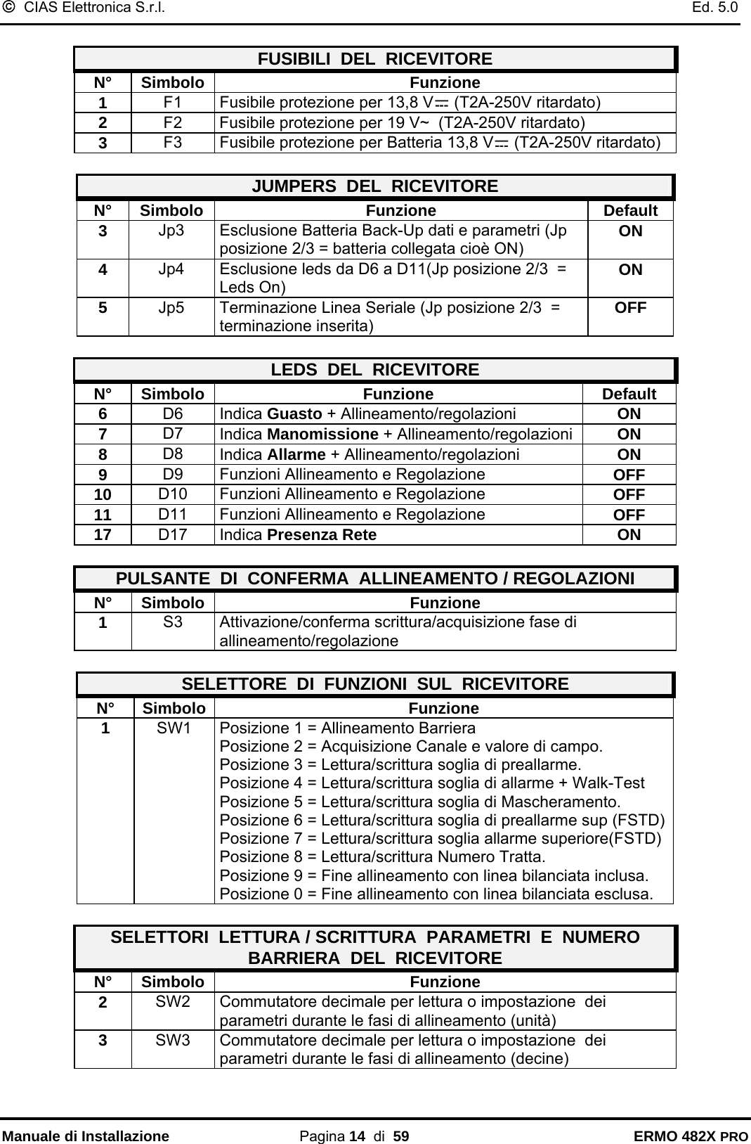
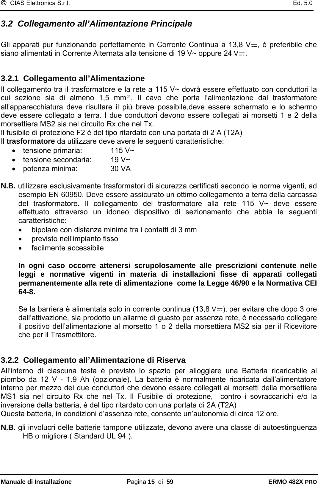
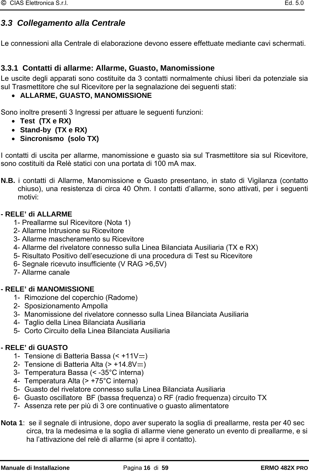
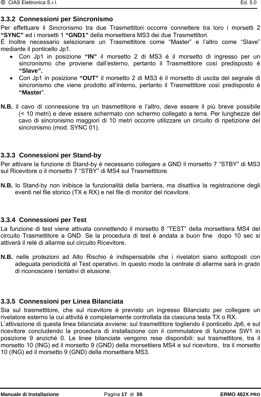
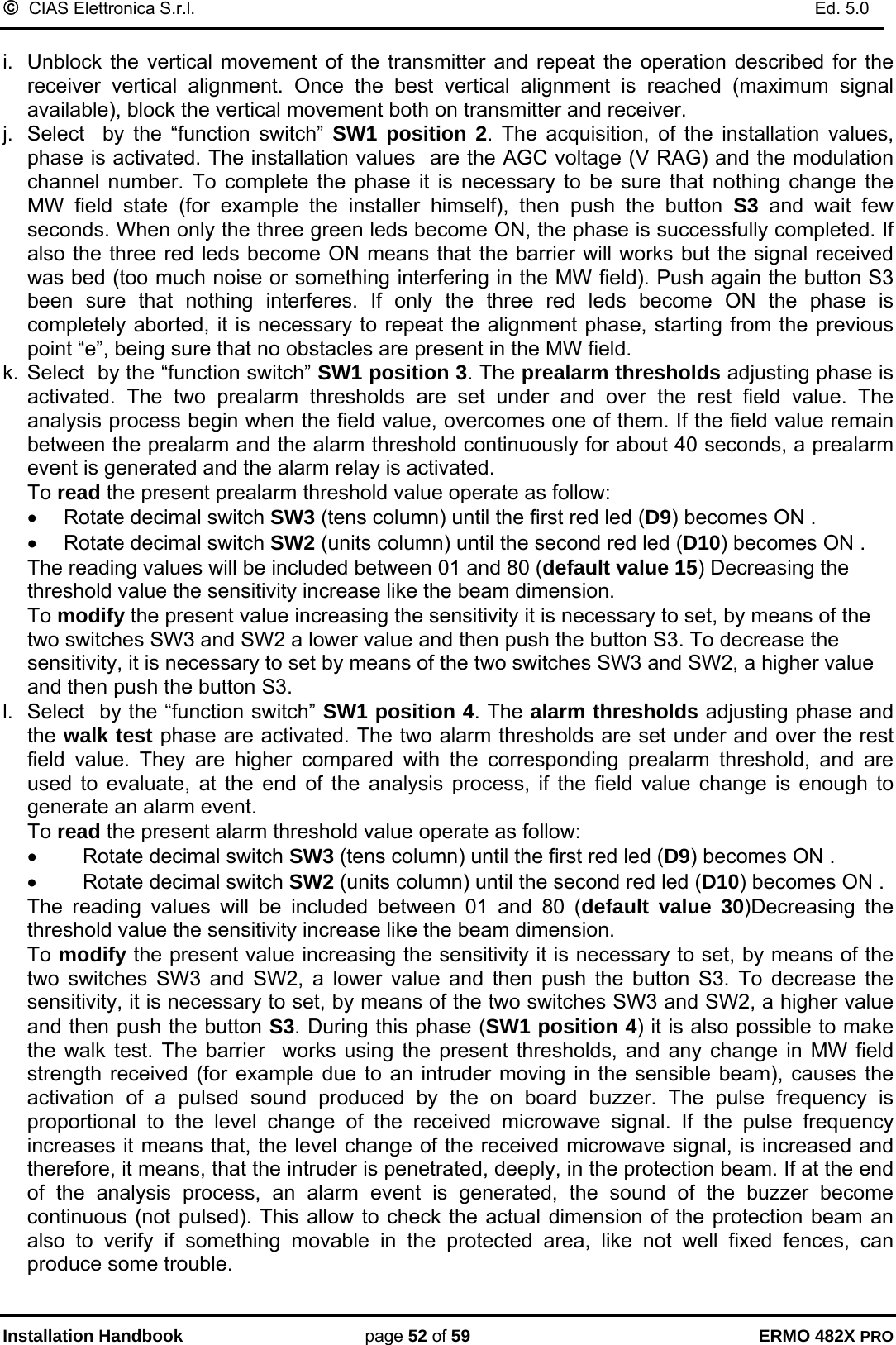
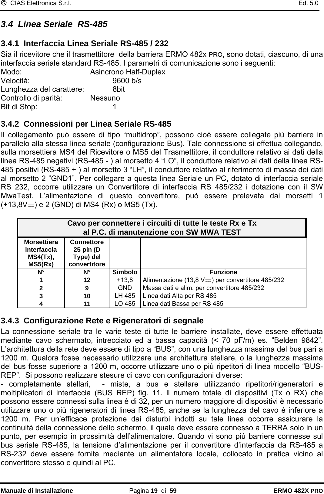
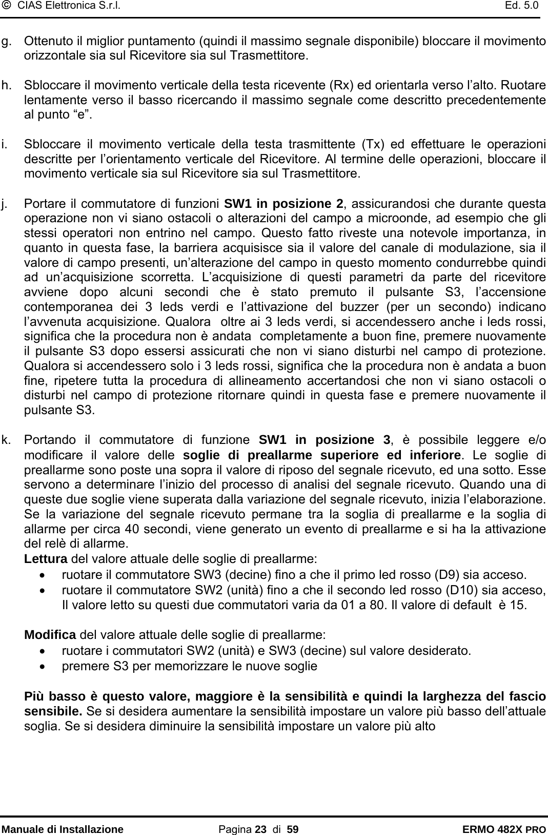
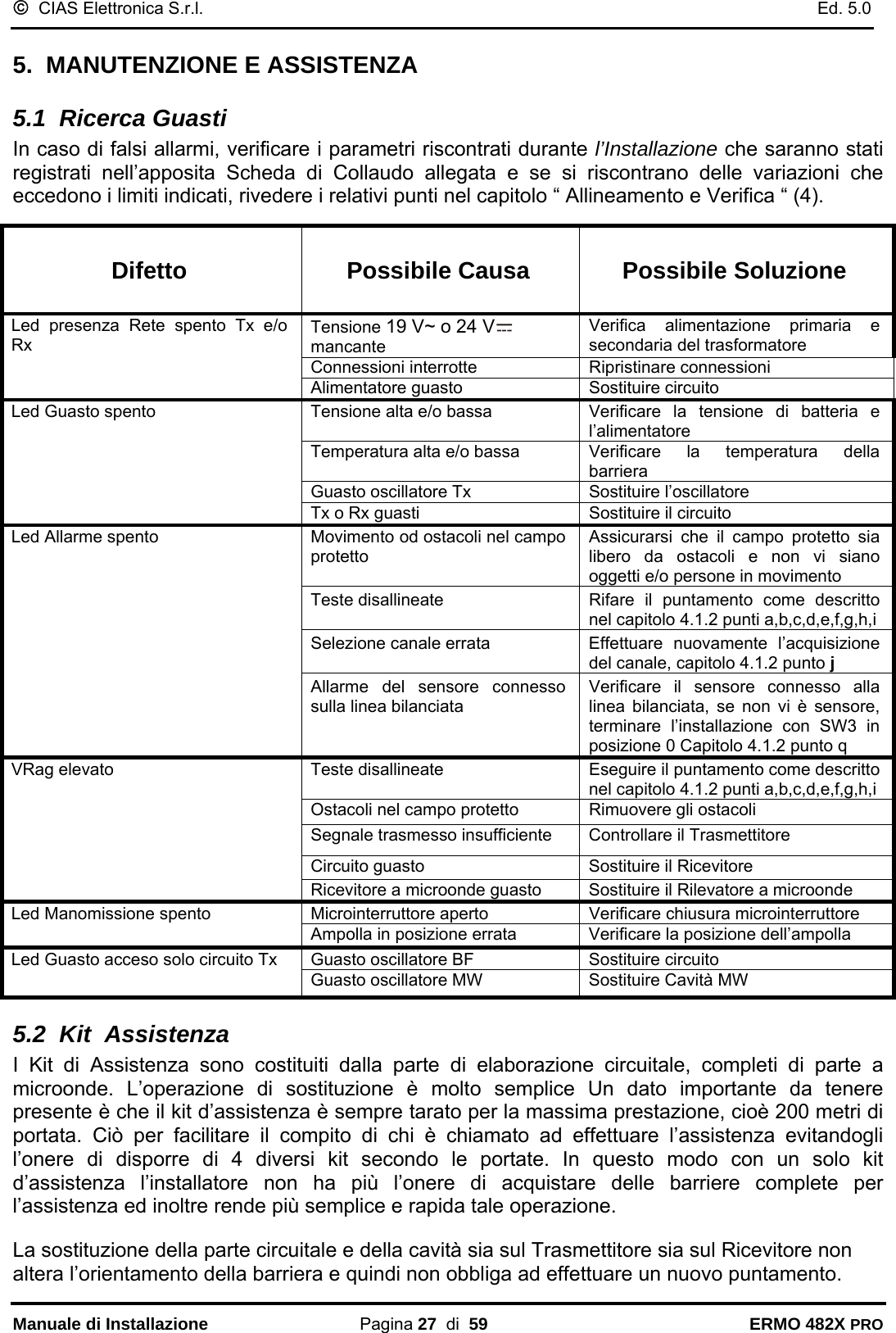
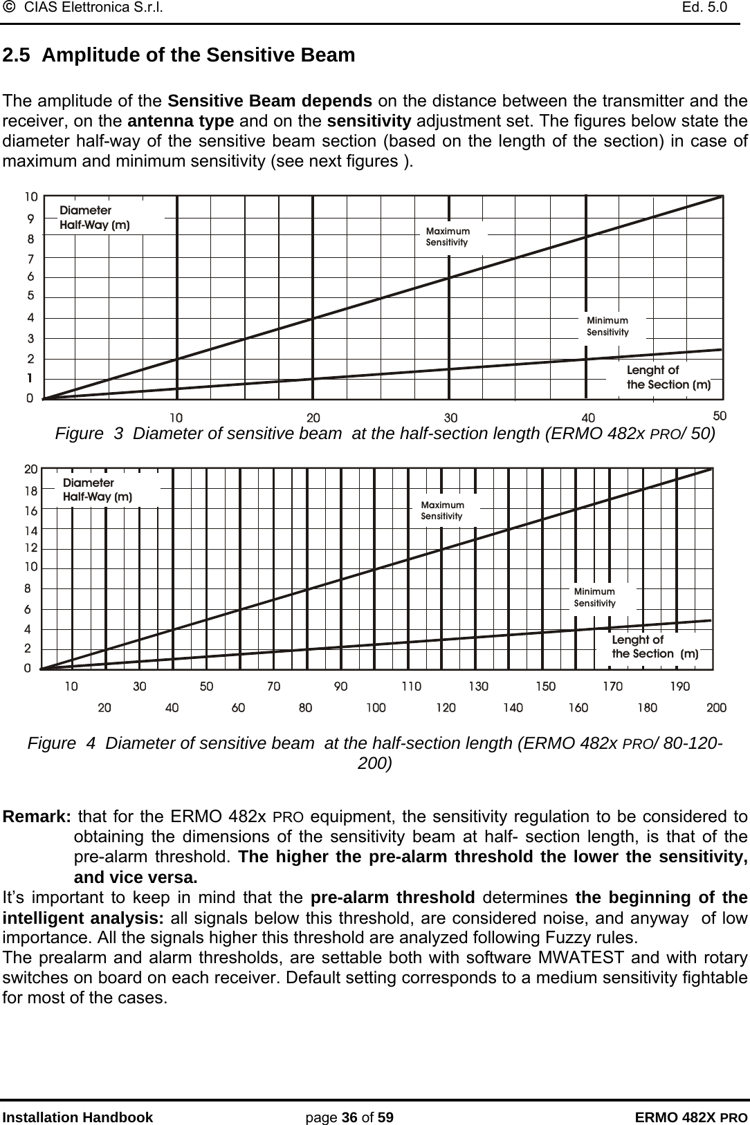
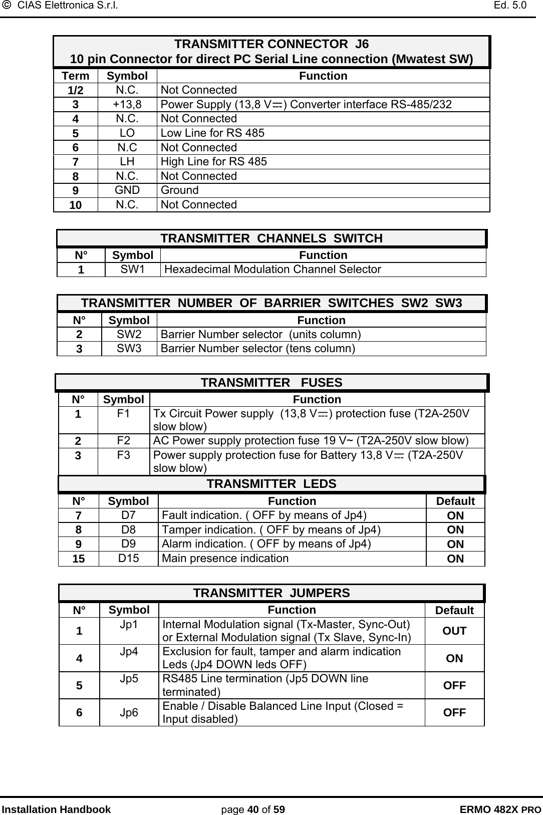
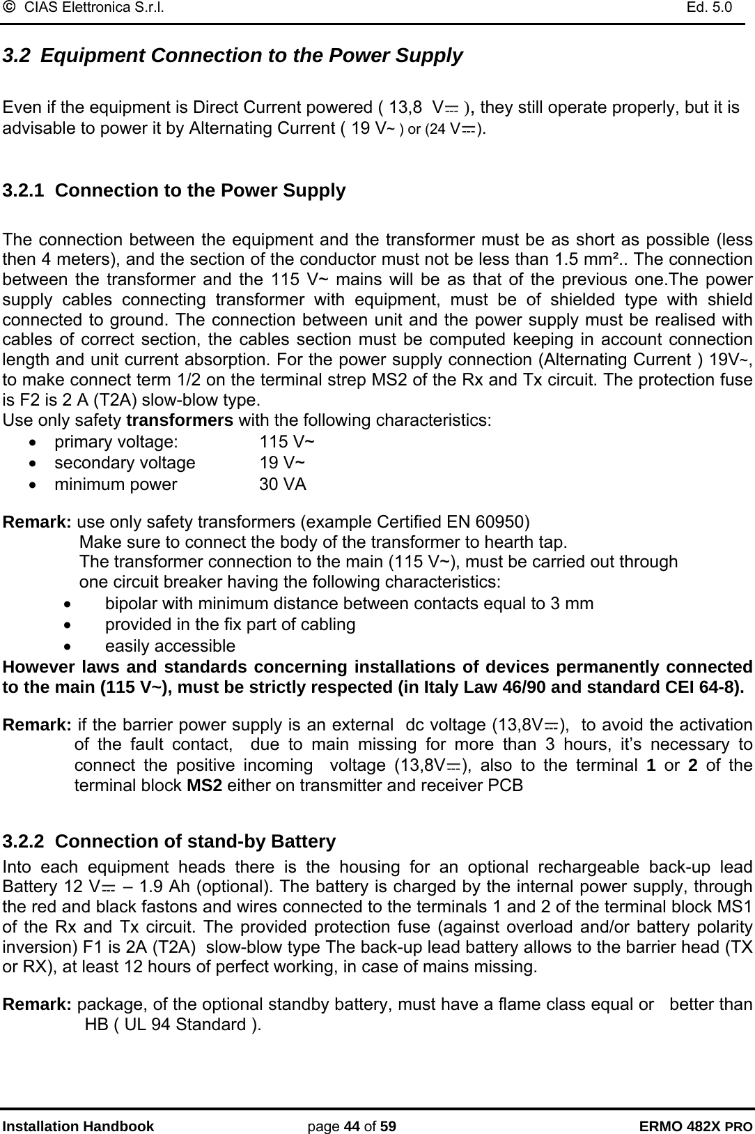
![© CIAS Elettronica S.r.l. Ed. 5.0 Manuale di Installazione Pagina 18 di 59 ERMO 482X PRO Per ciascun rivelatore esterno possono essere gestiti gli stati di: • riposo • allarme • manomissione • guasto Possono inoltre essere gestiti gli stati di: • taglio Linea di collegamento tra rivelatore e testa (TX o RX) • corto Circuito Linea di collegamento tra rivelatore e testa (TX o RX) Per ottenere la gestione di tutti questi stati occorre realizzare una pesatura mediante resistori collegati come nella seguente figura. 0- 0.5CORTO CIRCUITOSTATODELL’INGRESSOTENSIONE DI INGRESSO[V cc]TAGLIOGUASTOMANOMISSIONEALLARMERIPOSO 0.5 1 1.51.5 2 2.52.5 3 3.53.5 4 4.54.5 - 5Min. Med. Max. Nella tabella riportata sono indicati i valori di tensione che si localizzano sui morsetti di ingresso della linea bilanciata per i vari stati del rivelatore esterno e della linea che lo collega alla testa TX o RX. Questi valori possono essere letti anche mediante il SW MWA-TEST nella schermata “Valori Analogici”, sia con un PC collegato localmente che attraverso una connessione remota. AMP1MS1 MS2J2J3J4JP5SW3 SW2SW1S3D 17 S 1J1112233445678910INGGNDTESTST.BYGTS2GTS1PT 2PT 1ALL2ALL1L0LHGND113,8VGND112+13,8 V1219V~19V~D7D9 D6 D8D10D11470 Ω470 Ω1K1,5KΩΩRIVELATORE ESTERNOSCHEDA RICEVITOREMS3 MS4](https://usermanual.wiki/CIAS-Elettronica-S-R-L/ERMO-482X-PRO/User-Guide-525218-Page-19.png)
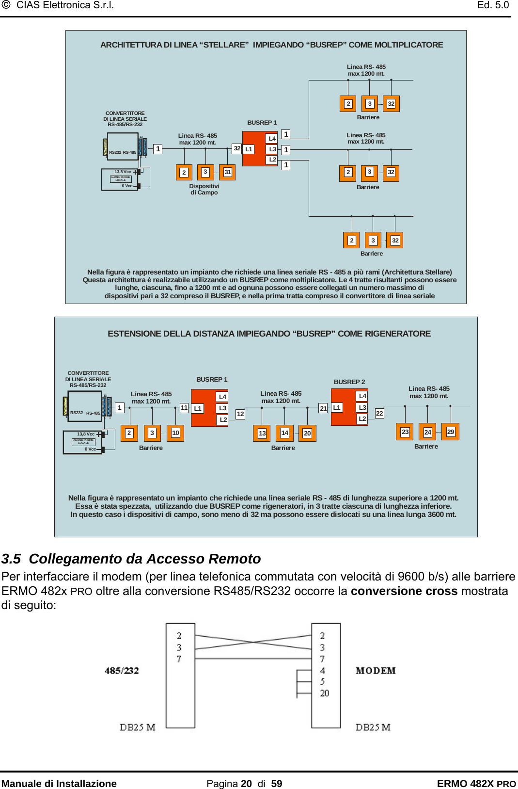
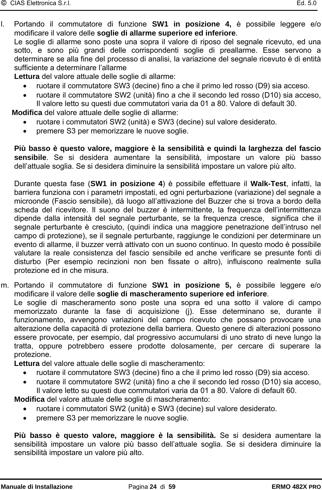
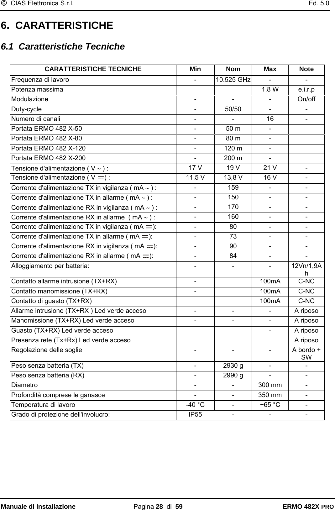

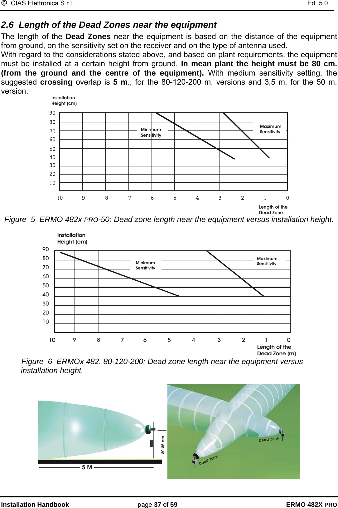
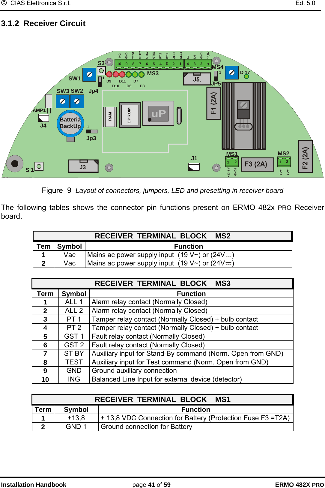
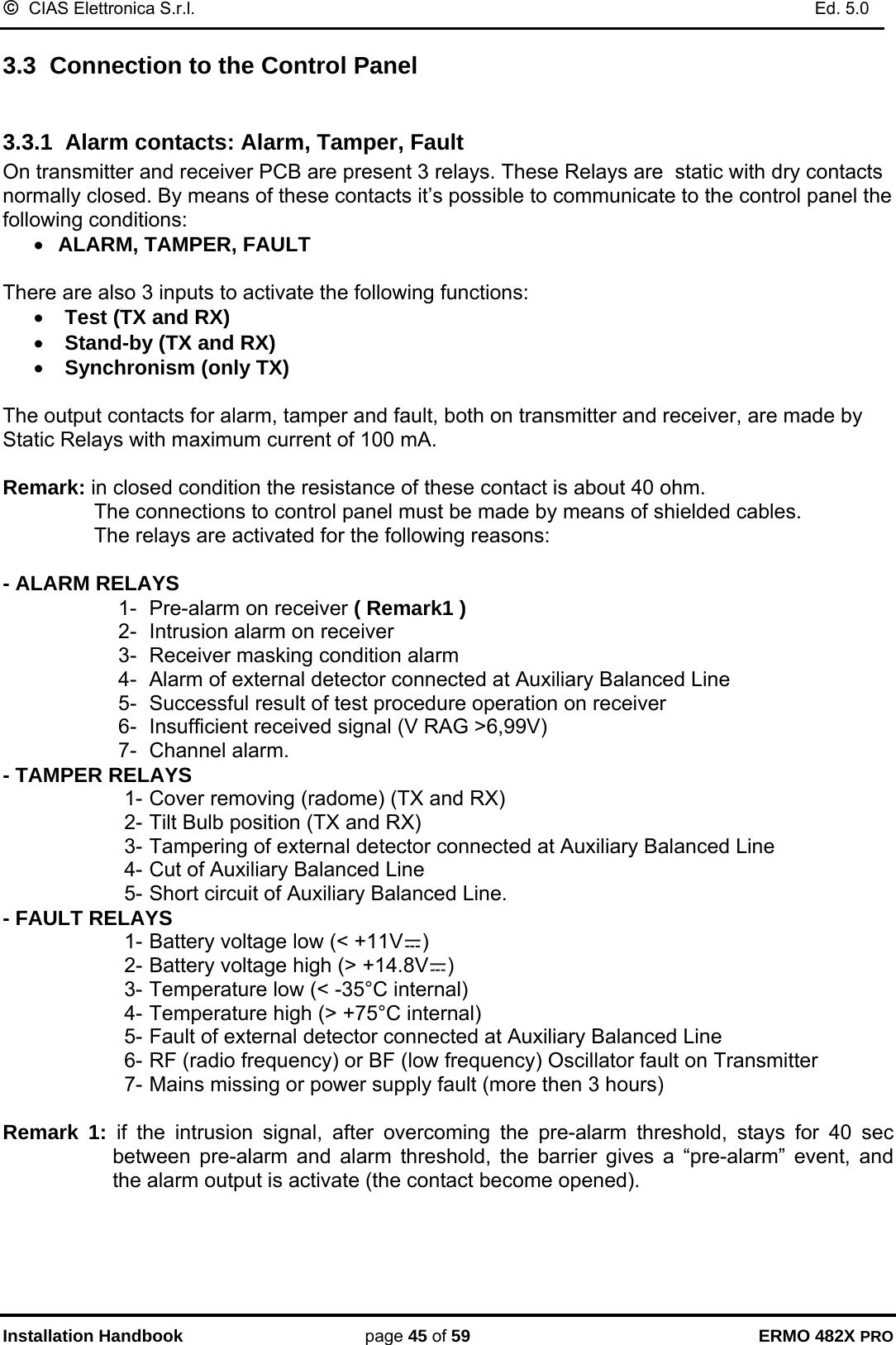
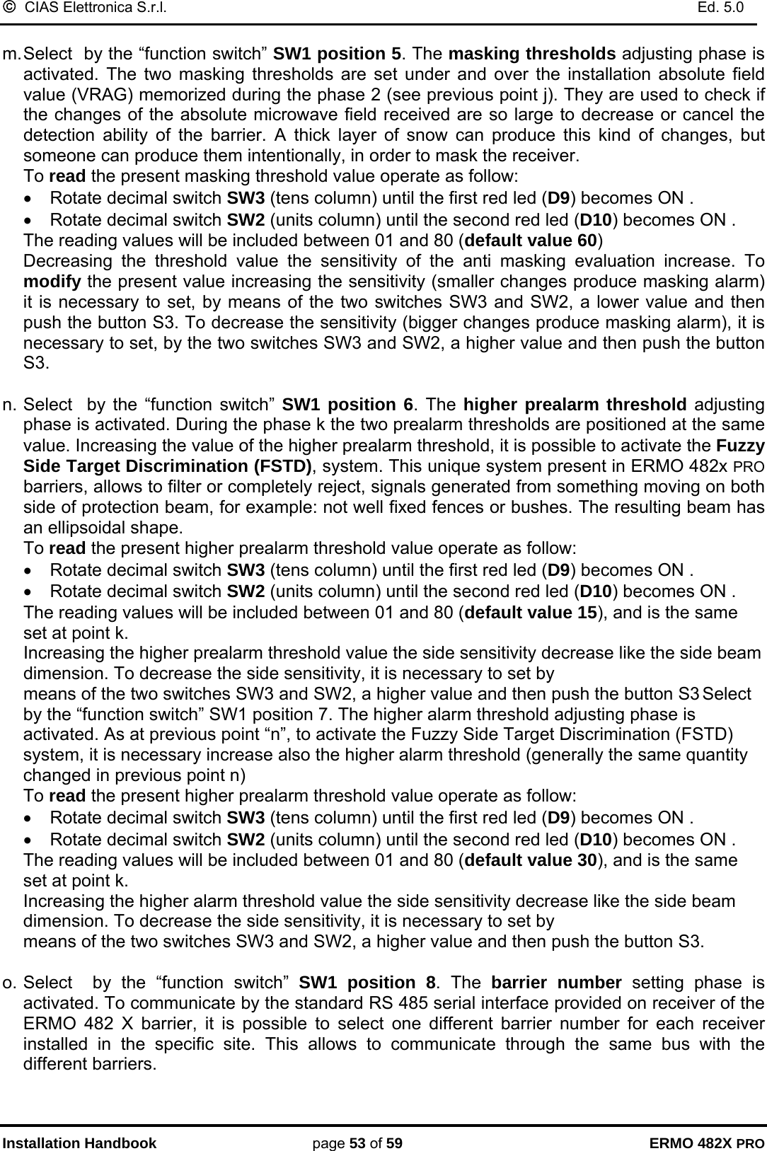
![© CIAS Elettronica S.r.l. Ed. 5.0 Installation Handbook page 47 of 59 ERMO 482X PRO In addition it’s possible to manage the following conditions: • Line cut condition of the wires connecting the external detector at TX or RX PCB • Short Circuit condition of the wires connecting the external detector at TX or RX PCB To manage all these conditions it’s necessary to use weighting resistors connected like that showed in the following picture. RECEIVER PCBAMP1MS1 MS2J2J3J4JP5SW3 SW2SW1S3D 17 S 1J1112233445678910INGGNDTESTST.BYGTS2GTS1PT 2PT 1ALL2ALL1L0LHGND113,8VGND112+13,8 V1219V~19V~D7D9 D6 D8D10D11MS3 MS4470 Ω470 Ω1K1,5KΩΩEXTERNAL DETECTOR In the following table are indicated the voltage values present at balanced inputs for the possible, detector and line, conditions. It is possible to read this values, also by means of MWA TEST SW in the “Analogue values” window. (PC in local or remote connection) 0- 0.5LINE SHORT CIRCUITCONDITIONS INPUT VOLTAGE[V dc]LINE CUTFAULTTAMPERALARMREST0.5 1 1.51.5 2 2.52.5 3 3.53.5 4 4.54.5 - 5Min. Average Max.](https://usermanual.wiki/CIAS-Elettronica-S-R-L/ERMO-482X-PRO/User-Guide-525218-Page-48.png)