CIAS Elettronica S R L ERMO-482X3PRO Microwave Barrier User Manual Ermo 482x PRO
CIAS Elettronica S.R.L. Microwave Barrier Ermo 482x PRO
UserManual.wiki
>
CIAS Elettronica S R L
>
ERMO 482X3PRO User Manual
Users Manual
Navigation menu
Upload a User Manual
Namespaces
Wiki Guide
HTML
PDF
Info
Views
User Manual
Discussion / Help
Navigation
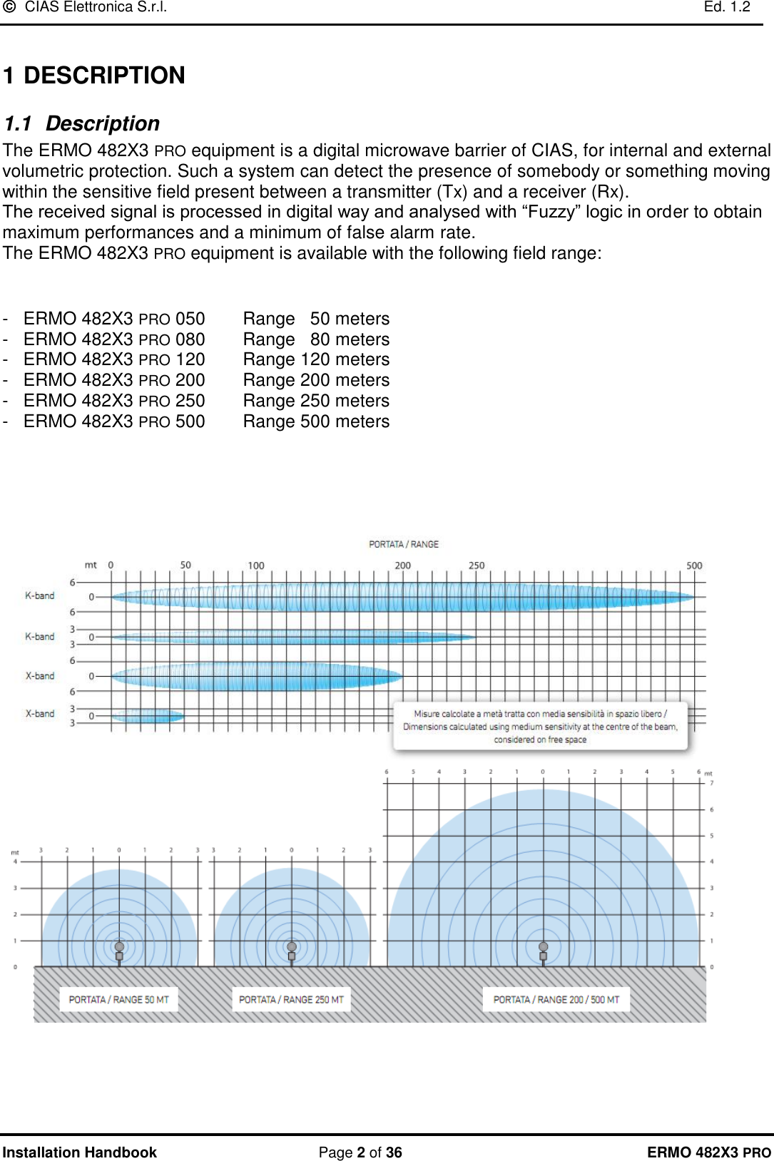
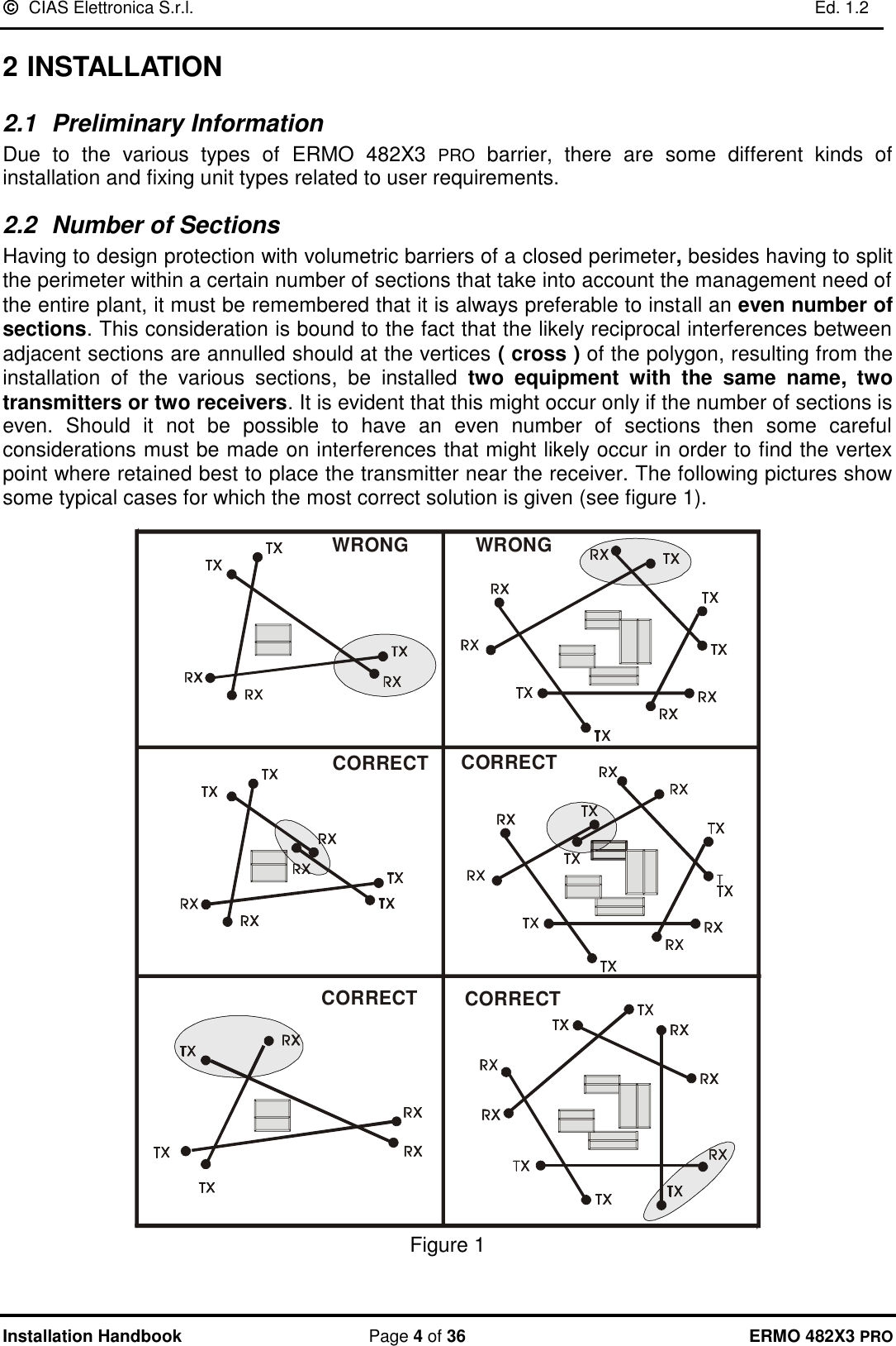
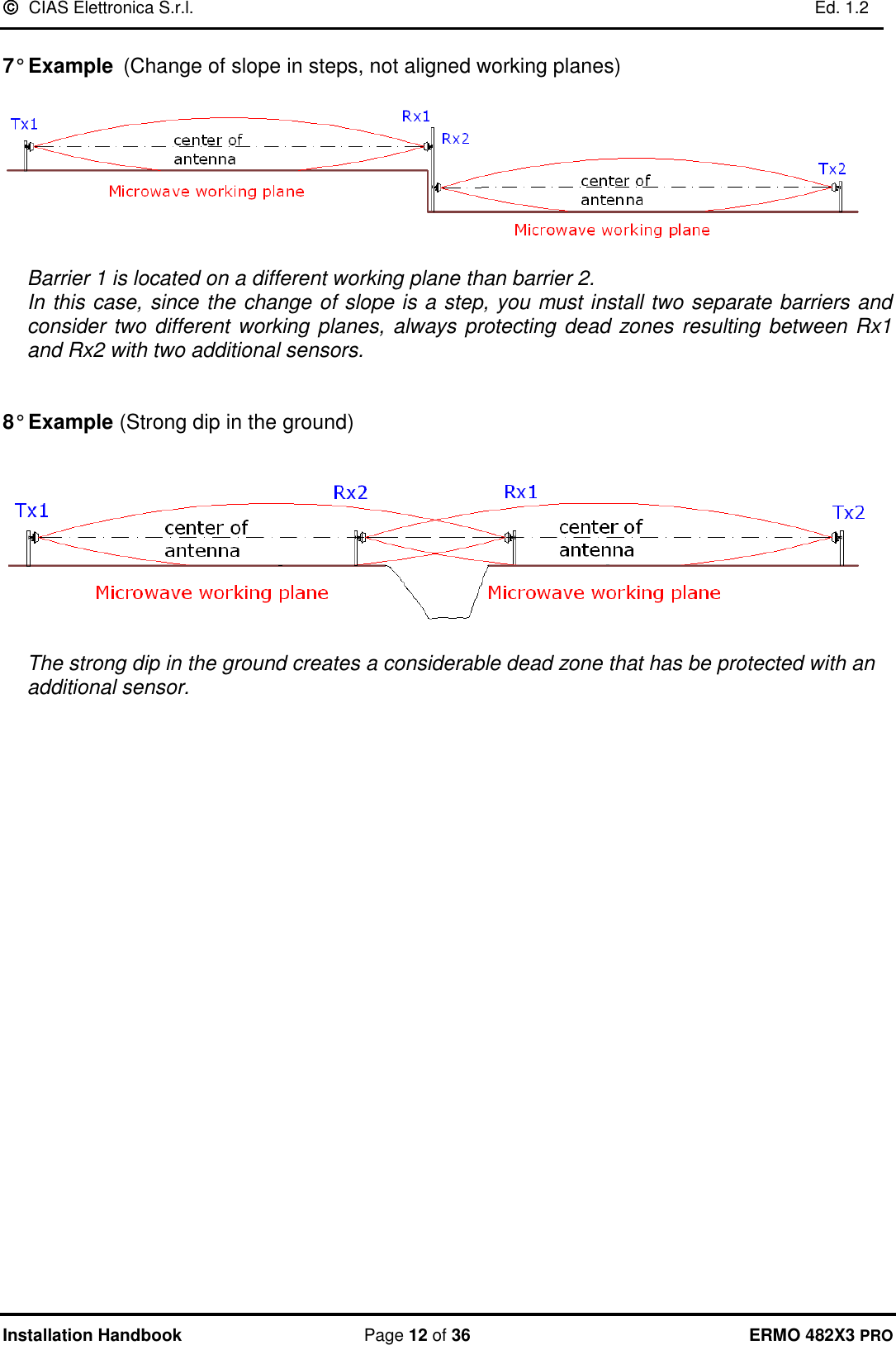
![ CIAS Elettronica S.r.l. Ed. 1.2 Installation Handbook Page 6 of 36 ERMO 482X3 PRO 2.5 Amplitude of the Sensitive Beam The amplitude of the Sensitive Beam depends on the distance between the transmitter and the receiver, on the antenna type and on the sensitivity adjustment set. The figures below state the diameter half-way of the sensitive beam section (based on the length of the section) in case of maximum and minimum sensitivity (see next figures). 123456789105 10 15 20 25 30 35 40 45 50Half rangesensitive zonediameter [m]Range [m]MaximumsensitivityMinimumsensitivity Figure 3 Diameter of sensitive beam at the half-section length (ERMO 482X3 PRO 50) 20 40 60 80 100 120 140 160 180 2002468101214161820 Half rangesensitive zonediameter [m]Range [m]MaximumsensitivityMinimumsensitivity Figure 4 Diameter of sensitive beam at the half-section length (ERMO 482X3 PRO 80-120-200)](https://usermanual.wiki/CIAS-Elettronica-S-R-L/ERMO-482X3PRO/User-Guide-3962758-Page-7.png)
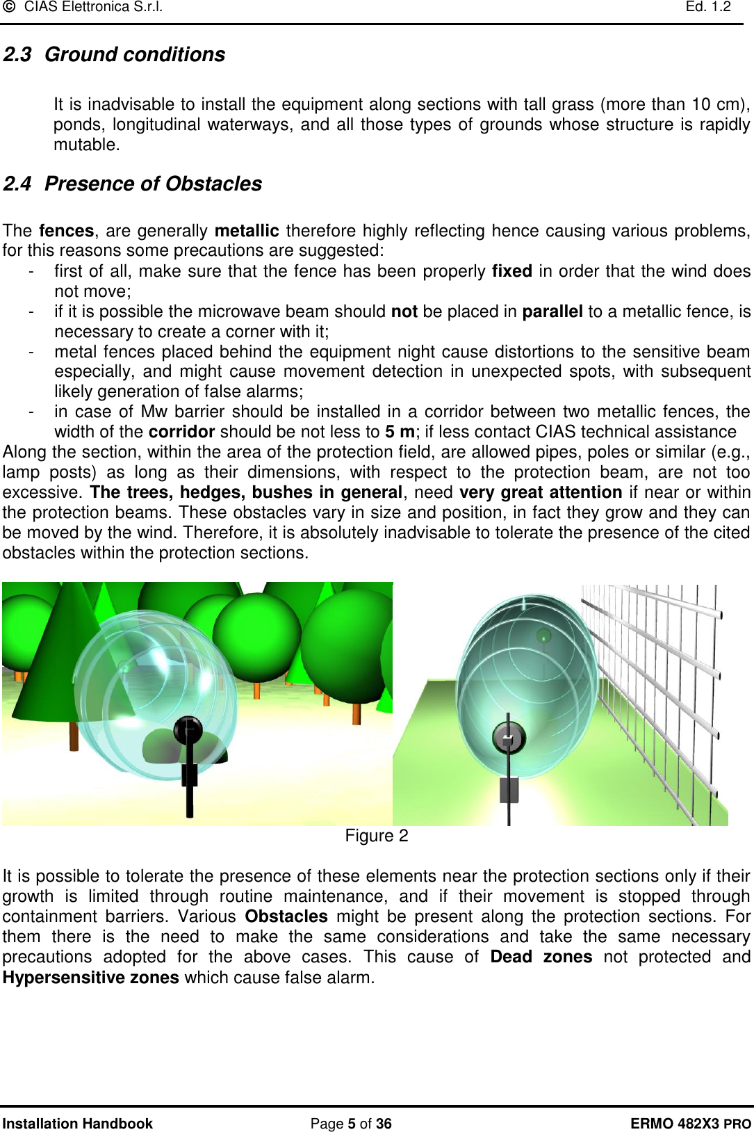
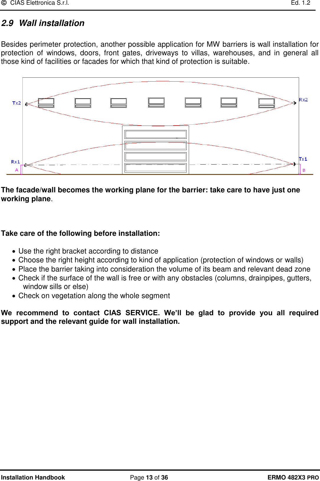
![ CIAS Elettronica S.r.l. Ed. 1.2 Installation Handbook Page 7 of 36 ERMO 482X3 PRO 51015202550 100 150 200 250 300 350 400 450 500Half rangesensitive zonediameter [m]Range [m]MaximumsensitivityMinimumsensitivity Figure 5 Diameter of sensitive beam at the half-section length (ERMO 482X3 PRO / 250-500) Remark: that for the ERMO 482X3 PRO equipment, the sensitivity regulation to be considered to obtaining the dimensions of the sensitivity beam at half- section length, is that of the pre-alarm threshold. The higher the pre-alarm threshold the lower the sensitivity, and vice versa. It’s important to keep in mind that the pre-alarm threshold determines the beginning of the intelligent analysis: all signals below this threshold, are considered noise, and anyway of low importance. All the signals higher this threshold are analyzed following Fuzzy rules. The prealarm and alarm thresholds, are settable both with software WAVE-TEST2 and with rotary switches on board on each receiver. Default setting corresponds to a medium sensitivity fightable for most of the cases.](https://usermanual.wiki/CIAS-Elettronica-S-R-L/ERMO-482X3PRO/User-Guide-3962758-Page-8.png)
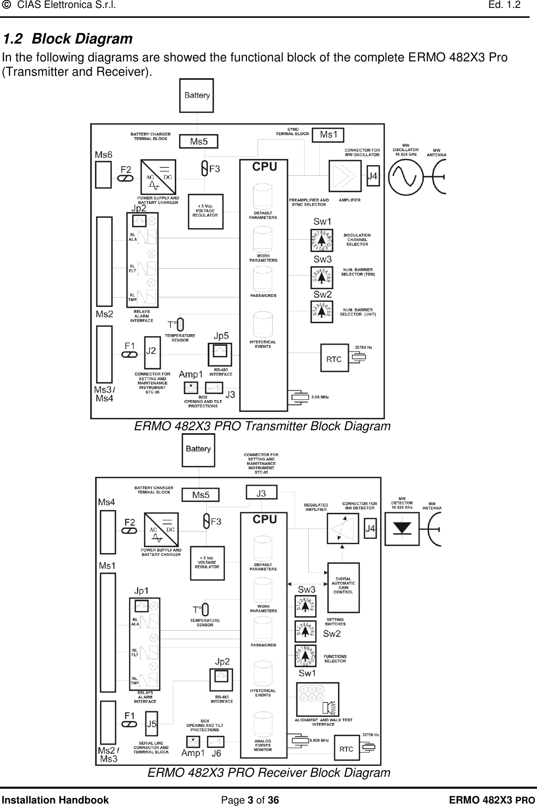
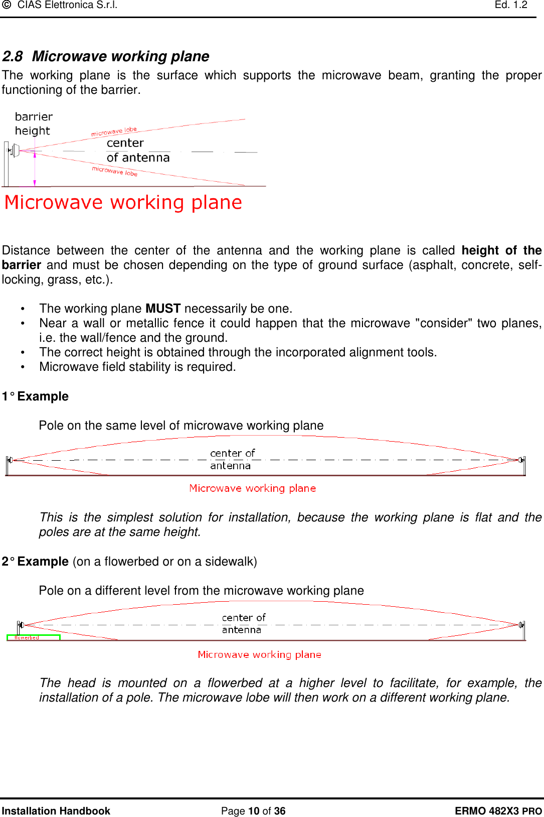
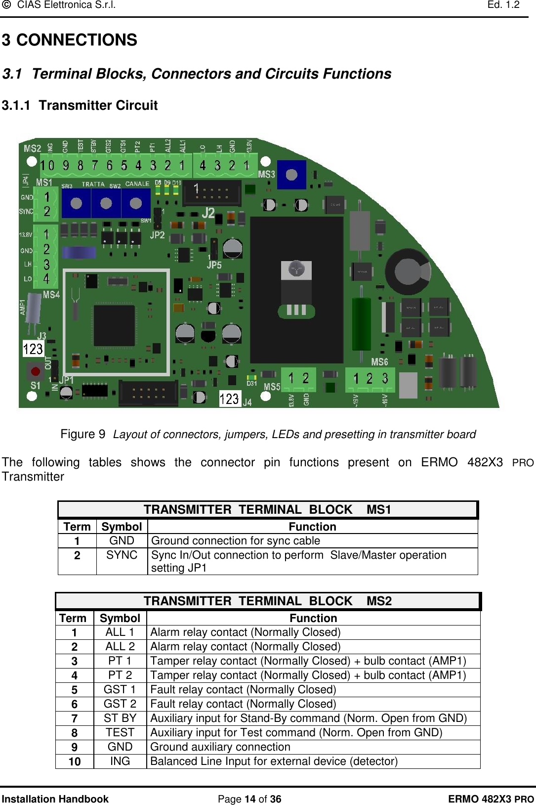
![ CIAS Elettronica S.r.l. Ed. 1.2 Installation Handbook Page 8 of 36 ERMO 482X3 PRO 2.6 Length of the Dead Zones near the equipment The length of the Dead Zones near the equipment is based on the distance of the equipment from ground, on the sensitivity set on the receiver and on the type of antenna used. With regard to the considerations stated above, and based on plant requirements, the equipment must be installed at a certain height from ground. In mean plant the height must be 80 cm. from the ground and the centre of the equipment (90cm for 50-250-500m barriers). With medium sensitivity setting, the suggested crossing overlap is 5m., for the 80-120-200m. 12,5m for 250-500m barriers versions and 3,5m. for the 50m. version. 203010405060708090100203010405060708090100123 4 5 67 8 9 10Antenna centreheight fromground [cm]Dead Zonelenght [m]Maximumsensitivity Minimumsensitivity Figure 6 ERMO 482X3 PRO 50: Dead zone length near the equipment versus installation height. 203010405060708090100203010405060708090100123 4 5 67 8 9 10Antenna centreheight fromground [cm]Dead Zonelenght [m]Maximumsensitivity Minimumsensitivity Figure 7 ERMO 482X3 PRO 80-120-200: Dead zone length near the equipment versus installation height.](https://usermanual.wiki/CIAS-Elettronica-S-R-L/ERMO-482X3PRO/User-Guide-3962758-Page-9.png)
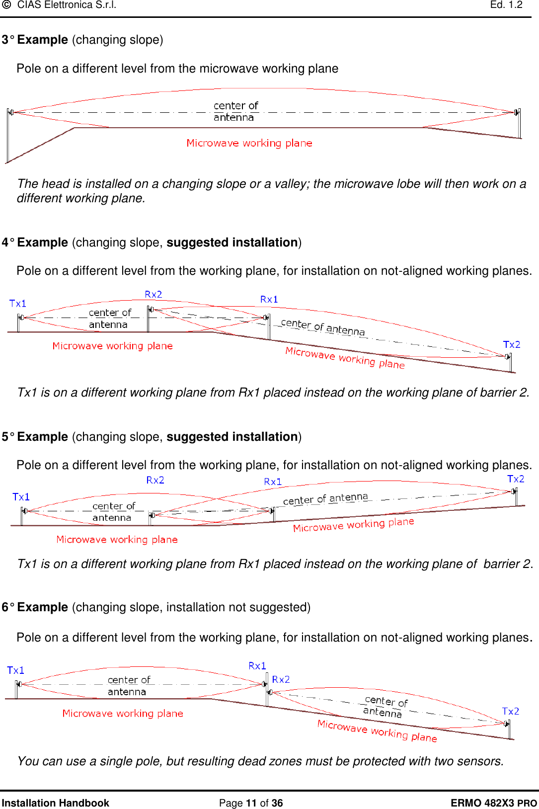
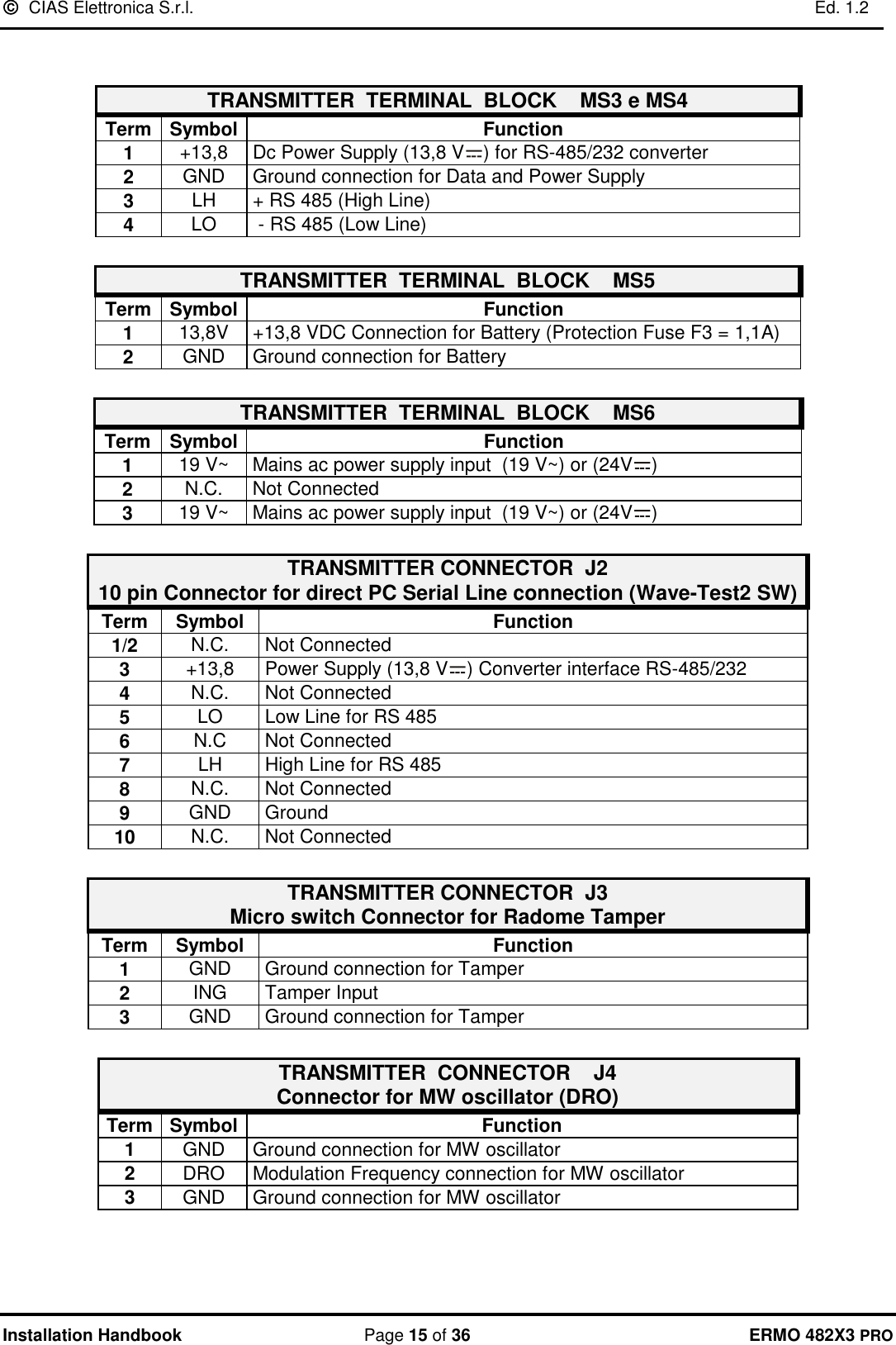
![ CIAS Elettronica S.r.l. Ed. 1.2 Installation Handbook Page 9 of 36 ERMO 482X3 PRO 2030104050607080901002030104050607080901002.5 5 7.5 10 12.5 15 17.5 20 22.5 25Antenna centreheight fromground [cm]Dead Zonelenght [m]Maximumsensitivity Minimumsensitivity Figure 8 ERMO 482X3 PRO 250-500: Dead zone length near the equipment versus installation height. 5 M80-85 cm Dead ZoneDead Zone 2.7 How to calculate the size of the beam and dead zones In order to calculate theoretically the dimension of the microwave beam and the dead zones generated with respect to the variable distance between TX and RX, CIAS has created a simple application called CIAS Volumeter available for free on our website: www.cias.it or on App Store to the following link: https://itunes.apple.com/it/app/cias-volumeter/id409397666?mt=8 or on Google play to the following link:https://play.google.com/store/apps/details?id=it.mi.action.ciasvolumeter](https://usermanual.wiki/CIAS-Elettronica-S-R-L/ERMO-482X3PRO/User-Guide-3962758-Page-10.png)
![ CIAS Elettronica S.r.l. Ed. 1.2 Installation Handbook Page 23 of 36 ERMO 482X3 PRO In addition it’s possible to manage the following conditions: • Line cut condition of the wires connecting the external detector at TX or RX PCB • Short Circuit condition of the wires connecting the external detector at TX or RX PCB To manage all these conditions it’s necessary to use weighting resistors connected like that showed in the following picture. In the following table are indicated the voltage values present at balanced inputs for the possible, detector and line, conditions. It is possible to read this values, also by means of WAVE-TEST2 SW in the “Analogue values” window. (PC in local or remote connection) 0 - 0.5LINE SHORT CIRCUITCONDITIONS INPUT VOLTAGE[V dc]LINE CUTFAULTTAMPERALARMREST 0.5 1 1.51.5 2 2.52.5 3 3.53.5 4 4.54.5 - 5Min. Average Max.](https://usermanual.wiki/CIAS-Elettronica-S-R-L/ERMO-482X3PRO/User-Guide-3962758-Page-24.png)
![This device complies with Part 15 of the FCC Rules [and with Industry Canada licence-exempt RSS standard(s)]. Operation is subject to the following two conditions. (1) This device may not cause harmful interference, and (2) This device must accept any interference received, including interference that may cause undesired operation. Le présent appareil est conforme aux CNR d'Industrie Canada applicables aux appareils radio exempts de licence. L'exploitation est autorisée aux deux conditions suivantes: (1) l'appareil ne doit pas produire de brouillage, et (2) l'utilisateur de l'appareil doit accepter tout brouillage radioélectrique subi, même si le brouillage est susceptible d'en compromettre le fonctionnement. NOTICE: Changes or modifications made to this equipment not expressly approved by CIAS Elettronica may void the FCC authorization to operate this equipment. NOTE: This equipment has been tested and found to comply with the limits for a Class B digital device, pursuant to Part 15 of the FCC Rules. These limits are designed to provide reasonable protection against harmful interference in a residential installation. This equipment generates, uses and can radiate radio frequency energy and, if not installed and used in accordance with the instructions, may cause harmful interference to radio communications. However, there is no guarantee that interference will not occur in a particular installation. If this equipment does cause harmful interference to radio or television reception, which can be determined by turning the equipment off and on, the user is encouraged to try to correct the interference by one or more of the following measures: • Reorient or relocate the receiving antenna. • Increase the separation between the equipment and receiver. • Connect the equipment into an outlet on a circuit different from that to which the receiver is connected. • Consult the dealer or an experienced radio/TV technician for help. IMPORTANT NOTE: Radiofrequency radiation exposure Information: This equipment complies with FCC radiation exposure limits set forth for an uncontrolled environment. This equipment should be installed and operated with minimum distance of 20 cm between the radiator and your body. This transmitter must not be co-located or operating in conjunction with any other antenna or transmitter. Copyright CIAS Elettronica S.r.l. Stampato in Italia / Printed in Italy CIAS Elettronica S.r.l. Direzione, Ufficio Amministrativo, Ufficio Commerciale, Laboratorio di Ricerca e Sviluppo Direction, Administrative Office, Sales Office, Laboratory of Research and Development 20158 Milano, via Durando n. 38 Tel. +39 02 376716.1 Fax +39 02 39311225 Web-site: www.cias.it E-mail: info@cias.it Stabilimento / Factory 23887 Olgiate Molgora (LC), Via Don Sturzo n. 17](https://usermanual.wiki/CIAS-Elettronica-S-R-L/ERMO-482X3PRO/User-Guide-3962758-Page-40.png)