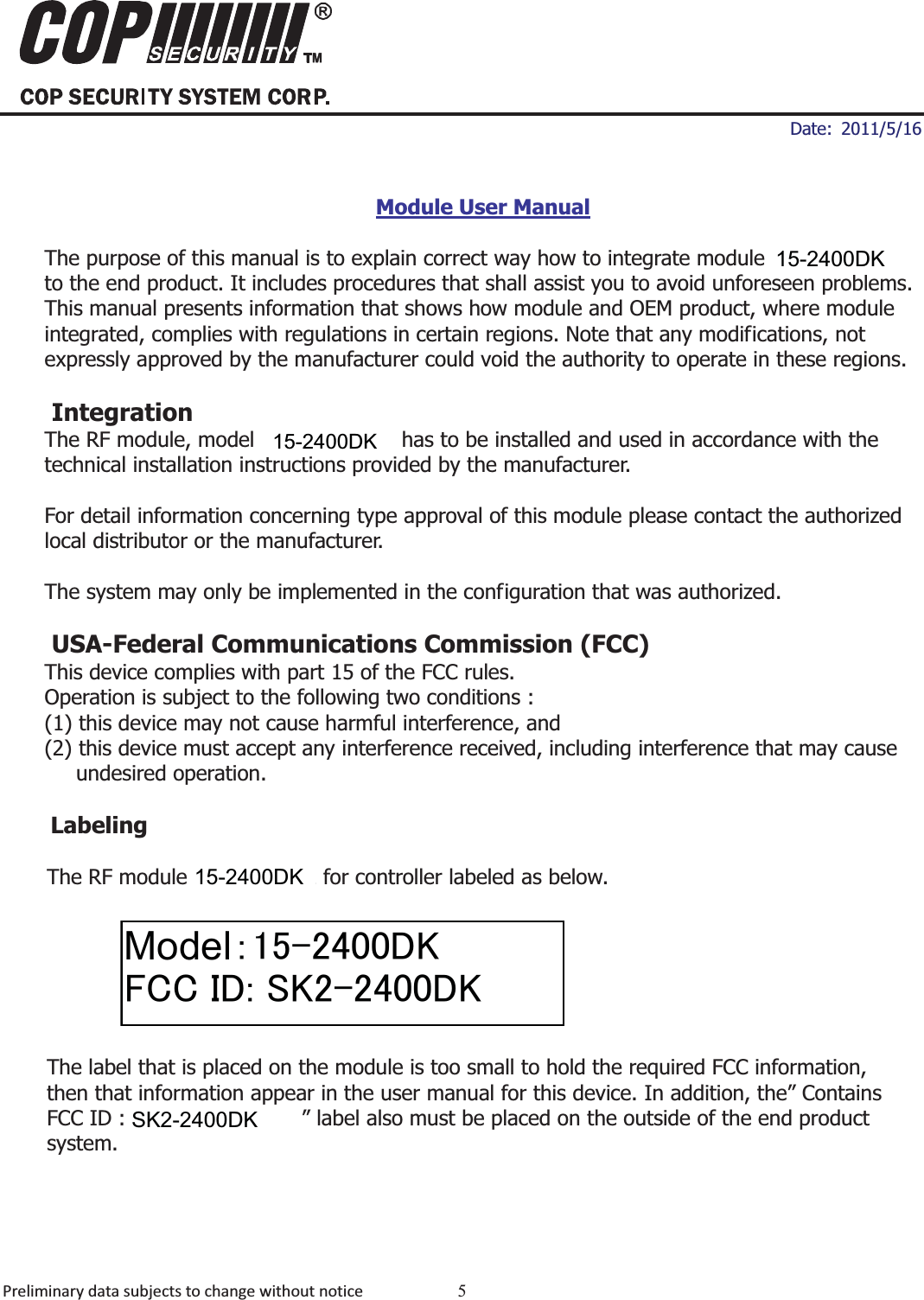
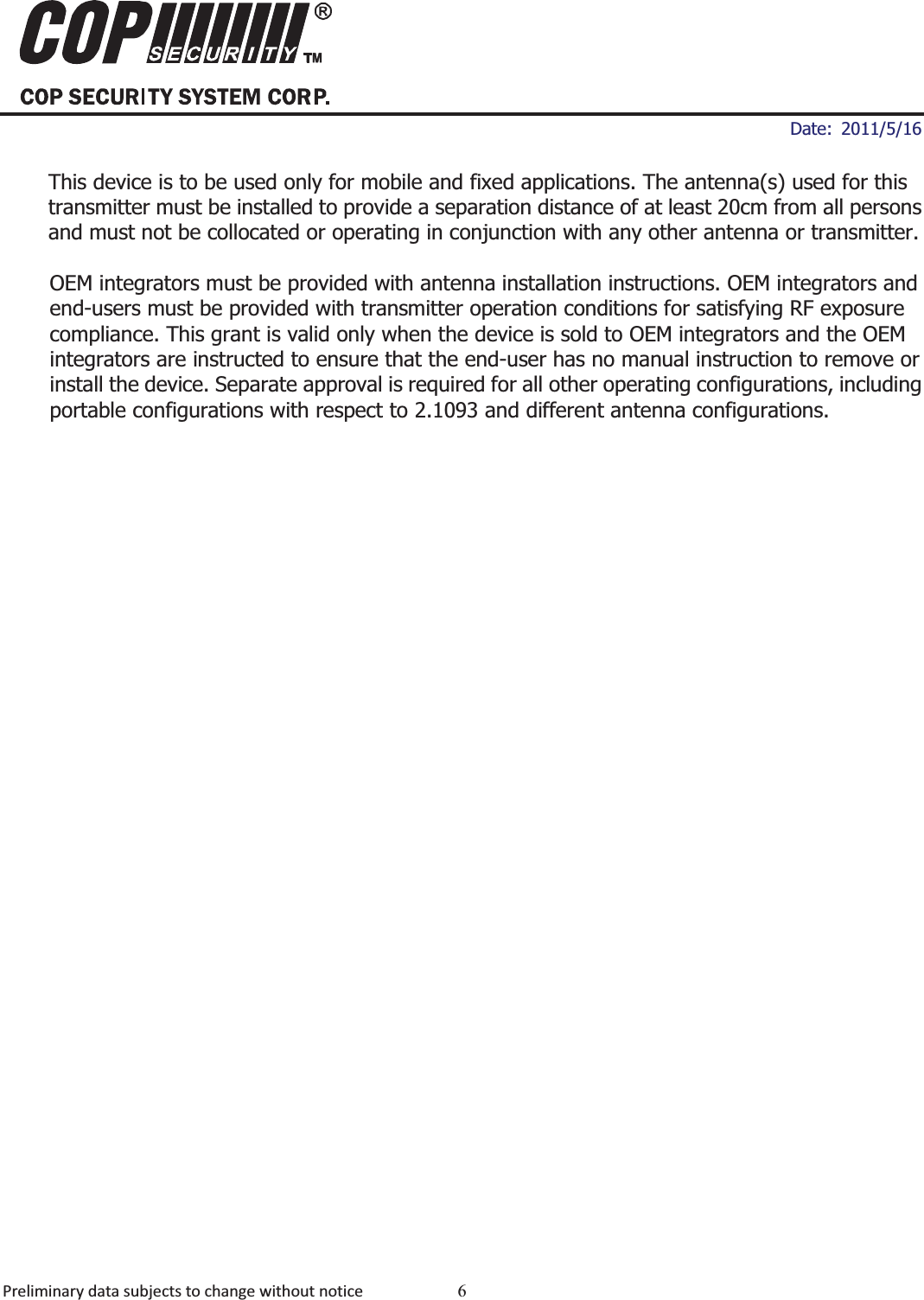
COP Security System 2400DK 2.4GHz Digital Wireless A / V / Data Transceiver Module User Manual

COP Security System Corp. 2.4GHz Digital Wireless A / V / Data Transceiver Module

user manual

ʳʳ ʳDate: 2011/5/16 Preliminarydatasubjectstochangewithoutnotice 1MDD-24R20012.4GHz Digital Audio Video ModulesA. FeaturesOperating frequency range from 2403 to 2475 MHz   Maximum 25 hopping channels Maximum data rate 12 Mbps (@16QAM) 4-wire SPI interface support max. 30MHz clock rate   Modulation scheme : 16QAM,QPSK The 16-bit CRC checking   Hardware retransmission for packets   Power supply range: 2.7 ~ 3.3V   Transmission range: 250 m (Line of sight) Outline: 20.40 x 27.65 x 4.4 mmCE & FCC compliance B. ApplicationsDigital AV Sender Digital Baby Monitor   Wireless Video Door phone   Security Camera   Portable Video Recorder      MDD-24R2001
ʳʳ ʳDate: 2011/5/16 Preliminarydatasubjectstochangewithoutnotice 2MDD-24R20012.4GHz Digital Audio Video ModulesC: SpecificationParameter Min. Typ. Max. UnitElectrical SectionSupply Voltage   4.9  5.0  5.1  VSupply current in TX mode   200 mASupply current in RX mode  65 mARF SectionModulation Mode  QPSK,16QAM   Operating Frequency  2403  ~  2475  MHz Channel Bandwidth    3    MHz Channel 25 channels Data Rate  3M  ~  12M  bps Transmitter Section Transmission Power +14 @16QAM +18 @QPSK  dBm Power control range 40 dB Power control resolution  1 1 3 dB Receiver Section Overlay channel spacing  1  MHz Sensitivity  -78 @ 16QAM -86 @ QPSK dBm OperationOperating Temperature  -10  ~  +60  кStorage Temperature  -20  ~  +70  к
ʳʳ ʳDate: 2011/5/16 Preliminarydatasubjectstochangewithoutnotice 3MDD-24R20012.4GHz Digital Audio Video ModulesD: Pin AssignmentNo. Marks Function 1 VCC Power Supply 2 GND Ground 3 CLK12M 12MHz clock output 4  IRQ_N  Interrupt indication for external MCU 5 CS_N Chip Selection 6  SDO  Serial data output 7  SDI  Serial data input 8 SCK Serial clock input 9  RST_N  Negative active reset input 10  CLK32K  32KHz clock output Model: MDD-24R2001
ʳʳ ʳDate: 2011/5/16 Preliminarydatasubjectstochangewithoutnotice 4MDD-24R20012.4GHz Digital Audio Video ModulesE: Mechanical Dimension
ʳʳ ʳDate: 2011/5/16 Preliminarydatasubjectstochangewithoutnotice 5MDD-24R20012.4GHz Digital Audio Video ModulesModule User ManualThe purpose of this manual is to explain correct way how to integrate module MDD-24R2001 to the end product. It includes procedures that shall assist you to avoid unforeseen problems. This manual presents information that shows how module and OEM product, where module integrated, complies with regulations in certain regions. Note that any modifications, not expressly approved by the manufacturer could void the authority to operate in these regions. Integration The RF module, model MDD-24R2001 has to be installed and used in accordance with the   technical installation instructions provided by the manufacturer. For detail information concerning type approval of this module please contact the authorized local distributor or the manufacturer. The system may only be implemented in the configuration that was authorized. USA-Federal Communications Commission (FCC) This device complies with part 15 of the FCC rules. Operation is subject to the following two conditions :   (1) this device may not cause harmful interference, and   (2) this device must accept any interference received, including interference that may cause   undesired operation. LabelingThe RF module MDD-24R002 for controller labeled as below. The label that is placed on the module is too small to hold the required FCC information, then that information appear in the user manual for this device. In addition, the” Contains FCC ID : O6L-MDD24R2001” label also must be placed on the outside of the end product system. 0RGHO䋺㪈㪌㪄㪉㪋㪇㪇㪛㪢㪝㪚㪚㩷㪠㪛㪑㩷㪪㪢㪉㪄㪉㪋㪇㪇㪛㪢6.'.'.'.'.
ʳʳ ʳDate: 2011/5/16 Preliminarydatasubjectstochangewithoutnotice 6MDD-24R20012.4GHz Digital Audio Video ModulesThis device is to be used only for mobile and fixed applications. The antenna(s) used for this transmitter must be installed to provide a separation distance of at least 20cm from all persons and must not be collocated or operating in conjunction with any other antenna or transmitter. OEM integrators must be provided with antenna installation instructions. OEM integrators and end-users must be provided with transmitter operation conditions for satisfying RF exposure compliance. This grant is valid only when the device is sold to OEM integrators and the OEM integrators are instructed to ensure that the end-user has no manual instruction to remove or install the device. Separate approval is required for all other operating configurations, including portable configurations with respect to 2.1093 and different antenna configurations.

Navigation menu