COP Security System 2400RS 2.4G Wireless Data Transceiver User Manual 15 2400RSK
COP Security System Corp. 2.4G Wireless Data Transceiver 15 2400RSK
UserManual.wiki
>
COP Security System
>
2400RS User Manual
(15-2400RSK)UserMan
Navigation menu
Upload a User Manual
Namespaces
Wiki Guide
HTML
PDF
Info
Views
User Manual
Discussion / Help
Navigation
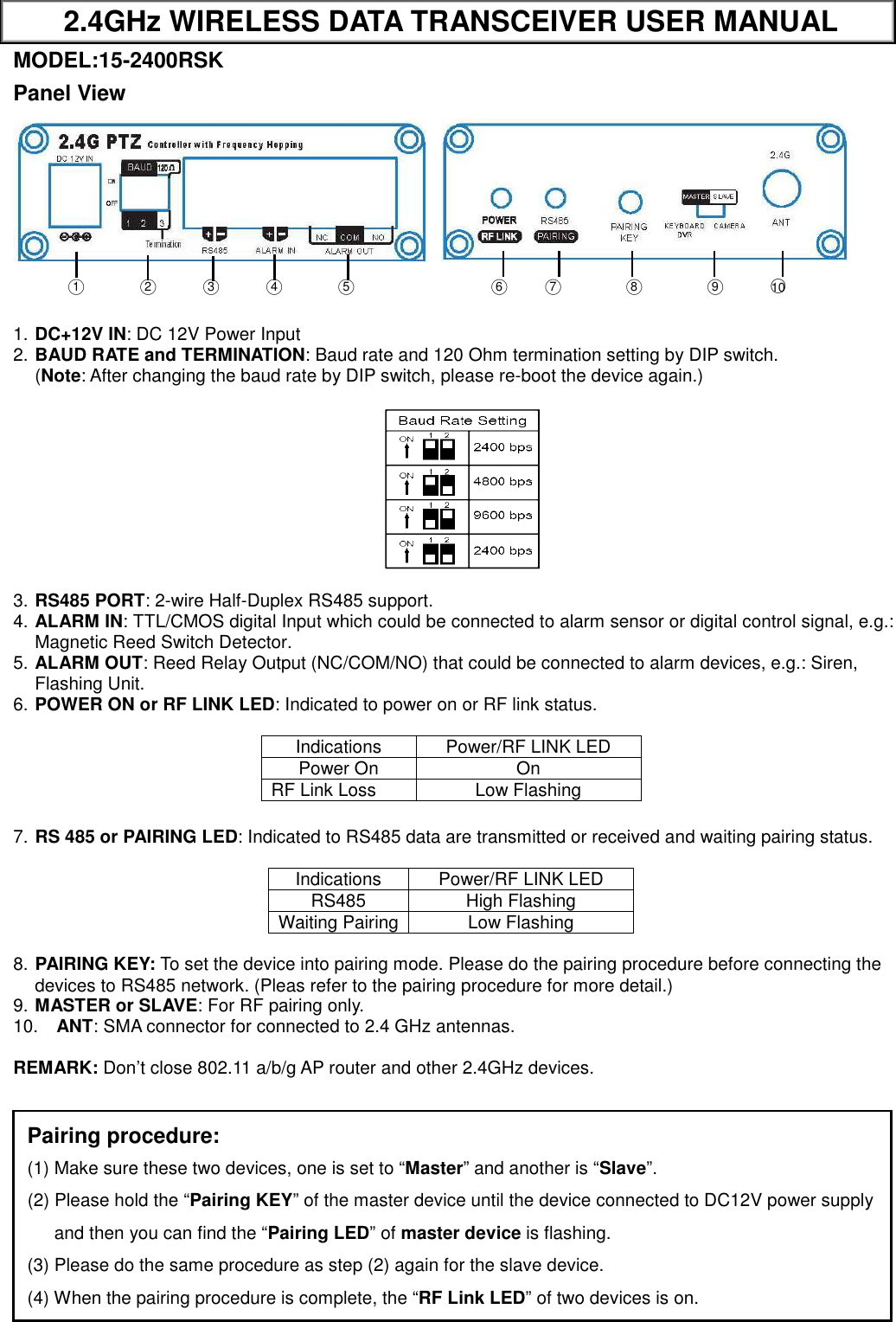
![2. Caution for Installation 2.1 Be careful, never let any water in this equipment. 2.2 If necessary, use a soft cloth moistened with alcohol to wipe off the dust. 2.3 Be extra careful not to shake the unit. 2.4 Avoid places where temperatures exceed 55 o C or higher. 2.5 Avoid places where there are frequent vibrations or shocks. 2.6 When any abnormalities occur, make sure to unplug the unit and contact your local dealer. 3. Packing 3.1 Transceiver ×2 3.2 Antenna ×2 3.3 User manual ×1 3.4 Screws ×8 3.5 Plastic-Conical-Anchor ×8 3.6 Power Adaptor ×2 [Option] 4. Specification Items 15-2400RSK Frequency Channels 2402 ~ 2480 MHz,79-CH (CE/FCC) RF TX Power 100 mW (Average) Min. RX Sensitivity -86dBm RF Impedance 50Ω RS485 2-wire RS485 Half Duplex Data Baud Rate :2400/4800/9600 bps Fixed Format:1 Start bit, 1 Stop bit, 8 Data Bits, No Parity Dual Directional ALARM I/O -ALARM Input: TTL/CMOS -ALARM Output:NC/COM/NO (Dry Contact) Contact Rating: AC 125V / 0.5A ; DC 24V / 1A Power Consumption 60 mA Max. @ DC12V Weight (without antenna) < 124.8g (4.4 oz) Operation Temperature -10°C ~ 55°C Storage Temperature -30°C ~ 85°C Dimensions (W × L × H) (excluding connectors and without antenna) 92 × 75 × 25mm (3.62” × 2.95” × 1.00”) FCC Part 15 Notice: This equipment has been tested and found to comply with the limits for a Class B digital device, pursuant to part 15 of the FCC rules. These limits are designed to provide reasonable protection against harmful interference in a residential installation. This equipment generates, uses and can radiate radio frequency energy and, if not installed and used in accordance with the instructions, may cause harmful interference to radio communications. However, there is no guarantee that interference will not occur in a particular installation. If this equipment does cause harmful interference to radio or television reception, which can be determined by turning the equipment off and on, the user is encouraged to try to correct the interference by one or more of the following measures: -Reorient or relocate the receiving antenna. -Increase the separation between the equipment and receiver. -Connect the equipment into an outlet on a circuit different from that to which the receiver is connected. -Consult the dealer or an experienced radio/TV technician for help. 1. This Transmitter must not be co-located or operating in conjunction with any other antenna or transmitter. 2. This equipment complies with FCC RF radiation exposure limits set forth for an uncontrolled environment. This equipment should be installed and operated with a minimum distance of 20 centimeters between the radiator and your body. 3. Any changes or modifications (including the antennas) made to this device that are not expressly approved by the manufacturer may void the user’s authority to operate the equipment. Q2011/04/19](https://usermanual.wiki/COP-Security-System/2400RS/User-Guide-1462373-Page-2.png)