Capital Prospect TB318 Lighting Remote Control User Manual mTB318
Capital Prospect Ltd Lighting Remote Control mTB318
UserManual.wiki
>
Capital Prospect
>
TB318 User Manual
User manaul_revised
Navigation menu
Upload a User Manual
Namespaces
Wiki Guide
HTML
PDF
Info
Views
User Manual
Discussion / Help
Navigation
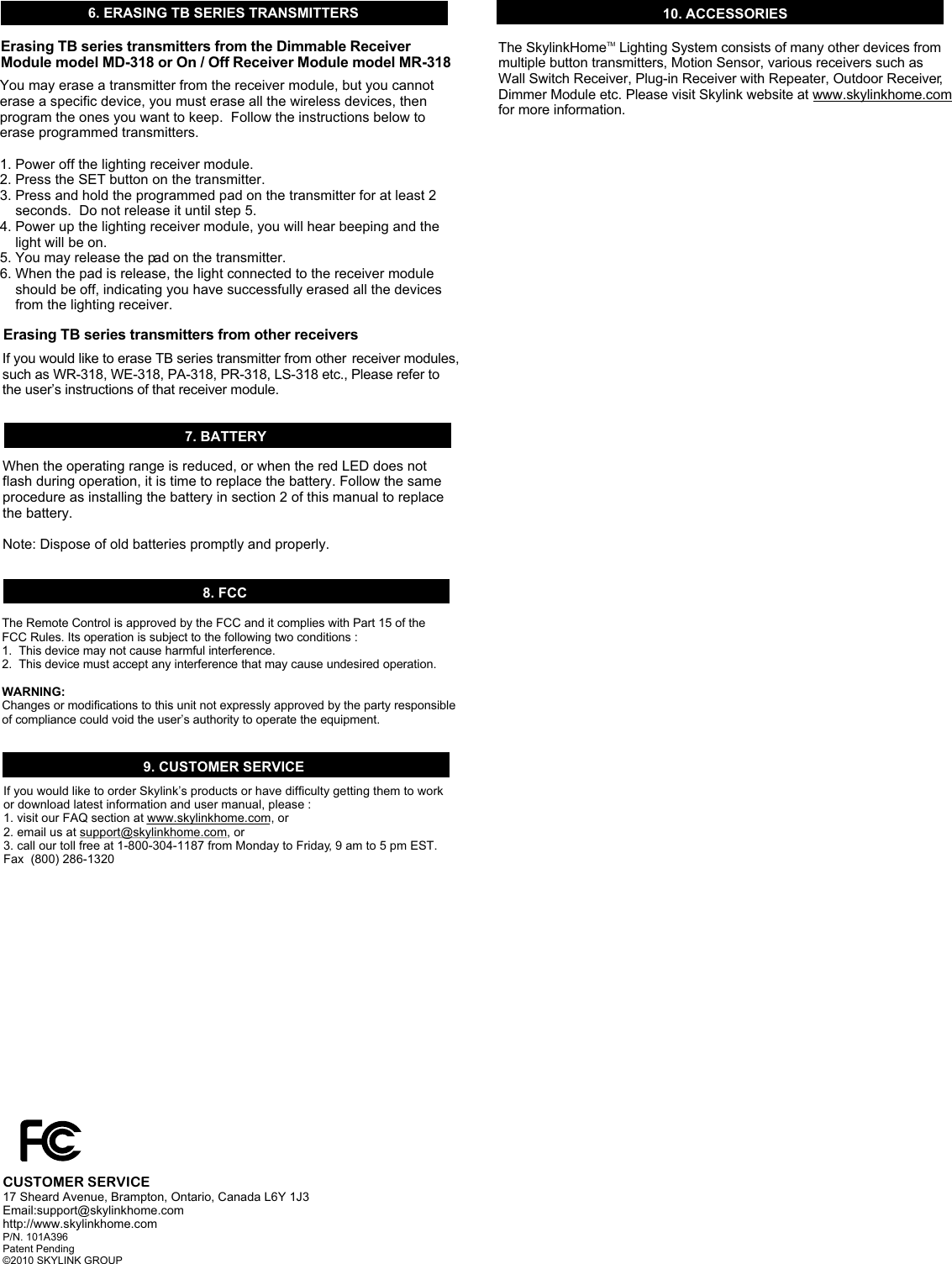
![1. INTRODUCTIONWall Mount TransmitterWall MountTransmitterModel TB-318AccessoriesLithium batteryDouble-sidedFoam TapeTMThank you for your purchase of a SkylinkHome Lighting Automation, Wall Mount Transmitter, Model TB-318. This transmitter allows you to TMwirelessly operate different lighting fixtures with the SkylinkHome lighting receiver modules. TMAll wireless signal communications within the SkylinkHome lighting system are based on rolling code technology to ensure highest security is used. You will find the following in this package:- Wall Mount Transmitter- Mounting Accessories & Double-sided Foam Tape - Lithium Battery CR-2032- User's InstructionsBefore you can control the lights with the transmitter, you need to program it to a receiver module. Follow the instructions below to program the trans-mitter to a receiver module. 2. PROGRAMMING TRANSMITTER TO RECEIVER MODULE 4. ON / OFF OPERATIONIn order to operate the receiver module remotely with a transmitter, it must be programmed to the receiver module. To program a transmitter into the receiver module, follow the instructions below. 1. Remove the wall plate from the Wall Mount Transmitter by loosening up the 2 screws.2. Insert the battery to the Wall Mount Transmitter as shown. Please note on the polarity, positive side up. When the battery is installed, the red LED on the transmitter will be on for 1 second. 3. Put the receiver module that you plan to program into programming mode. Refer to the User's Instructions of that receiver module. 4. Once the receiver module is in programming mode, you may transmit the programming signal from the transmitter by pressing the “SET” button on the transmitter. The red LED on the transmitter will be on. 5. Activate the Wall Mount Transmitter by pressing the pad on the front. Its red LED will flash then off. 6. Once the transmitter is programmed, the receiver module will quit from programming mode. 7. You may operate the light with the programmed transmitter. +Loosen up 2 screwsBattery(Positive side up)Red LEDSET ButtonPadPush pad toturn on / offPushHoldToggle the light on / offBrightness ControlPushHoldORCR 2032Tighten2 screwsPlace double-sidedfoam tape3. INSTALLATIONPushing the pad from one position to the other will toggle the light, i.e. when the light is off, pushing the pad will turn on the light, vice versa. 5. BRIGHTNESS CONTROL OPERATIONBesides turning on and off the light, you may also control the brightness of the light if the receiver module and the light bulb is dimmable, i.e. either incandescent light and designated dimming compact fluorescent light.To change the brightness, first turn on the light by pushing the pad. Press and hold the pad after the light is on will change the brightness of the light. Hold onto the button until the desired brightness is reached, then release the pad.Press and hold the pad again to alter the brightness (from dim to brighten, and from brighten to dim), until the desired brightness is reached, then release the pad. Slide inPush Down 20 32+ 2+After programming, you are now ready to install the Wall Mount Transmitter . You may use double sided foam tape to stick the transmitter on the wall, or you may use screws to mount the transmitter. Using double sided foam tape: Place the 2 double sided foam tape on the back of the back plate. Clean the surface of the wall where you plan to install the back plate. Peel off the foam tape and stick it to the wall surface. Using screws: If you are using screws, tighten the back plate of the wall mount trans-mitter by the 2 screws provided. If you are installing the back plate to an ]existing wall switch with gang box, no need to use the anchors. Other-wise, drill 2 small pilot holes based on the 2 mounting screw positions and insert the anchors before tightening the back plate with screws. After securing the back plate, either by double sided foam tape or screws, tighten the 2 screws on the front to secure the front plate. Existing Gang Box (No Anchor)Drill 2 pilot holes & insert anchors](https://usermanual.wiki/Capital-Prospect/TB318/User-Guide-1252051-Page-1.png)