Ceyon Technology REM125-5 RF-ID SYSTEM User Manual
Ceyon Technology Co., Ltd. RF-ID SYSTEM
UserManual.wiki
>
Ceyon Technology
>
REM125 5 User Manual
USERS MANUAL
Navigation menu
Upload a User Manual
Namespaces
Wiki Guide
HTML
PDF
Info
Views
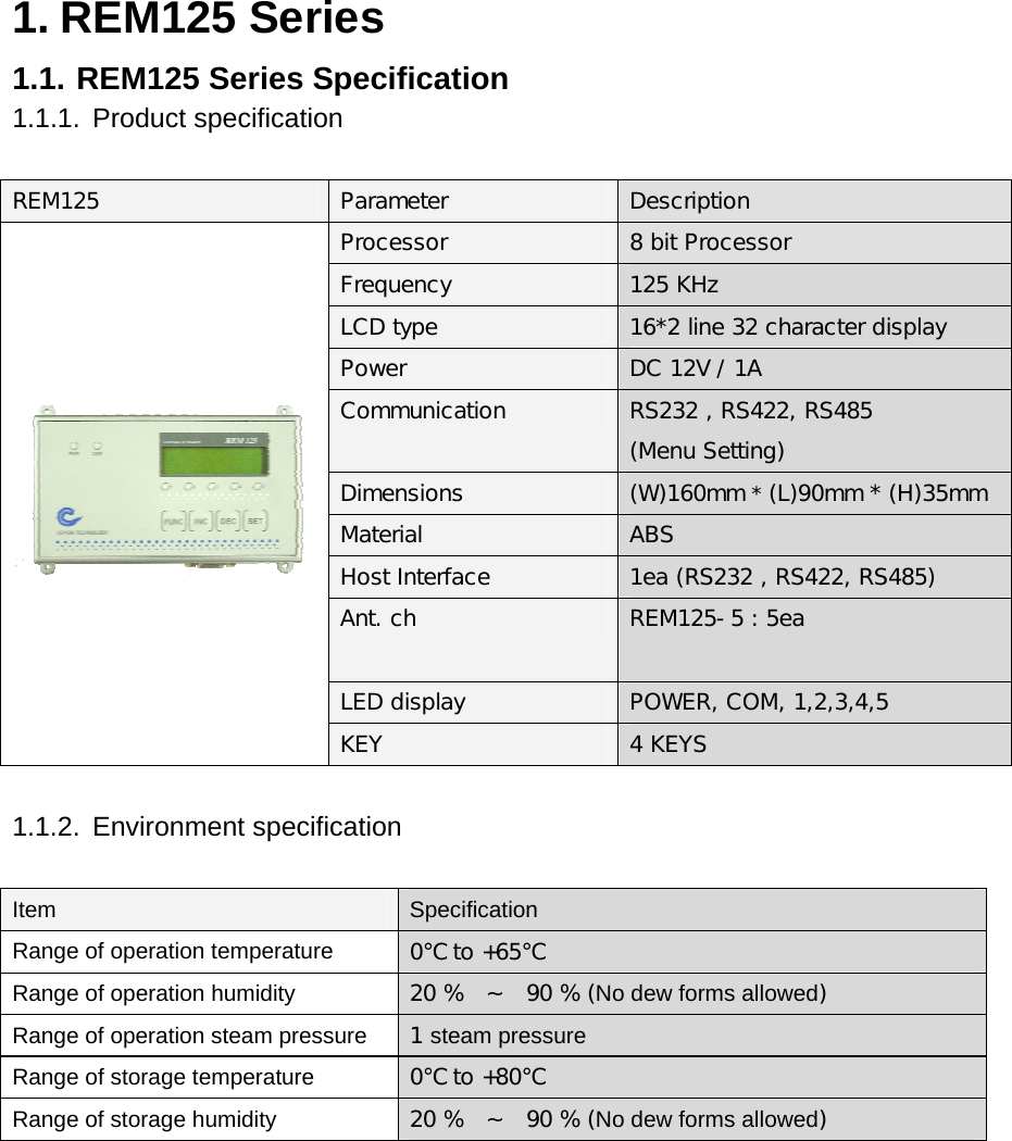
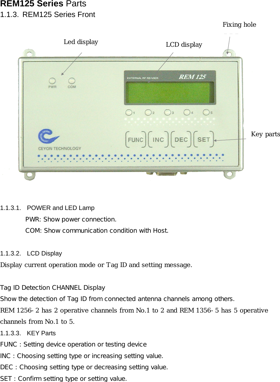
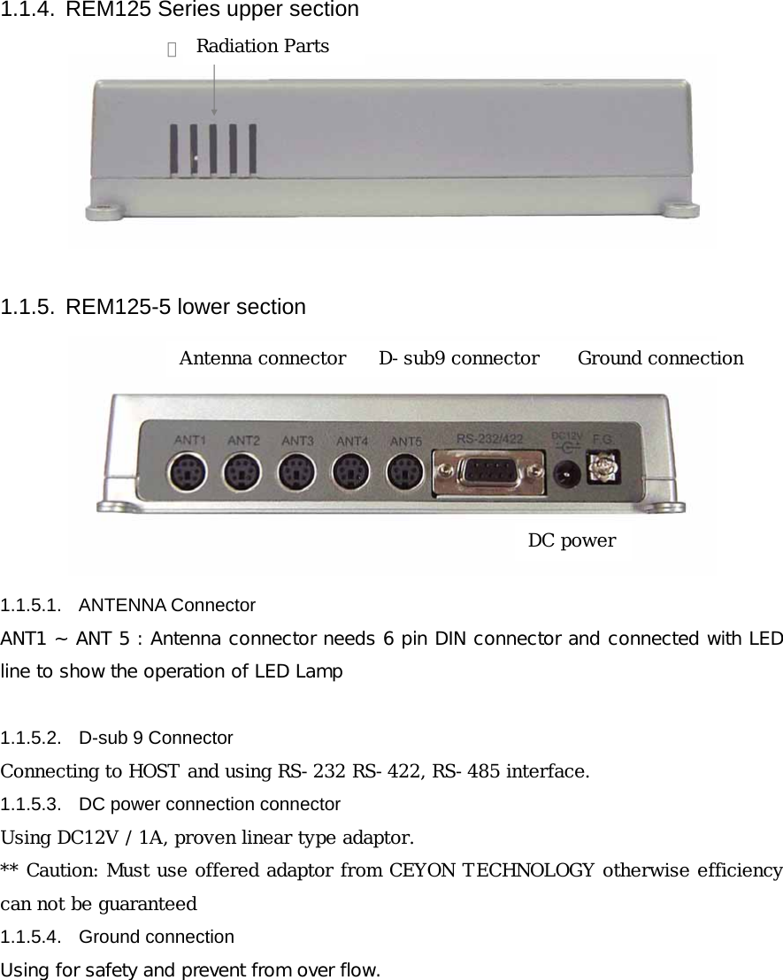
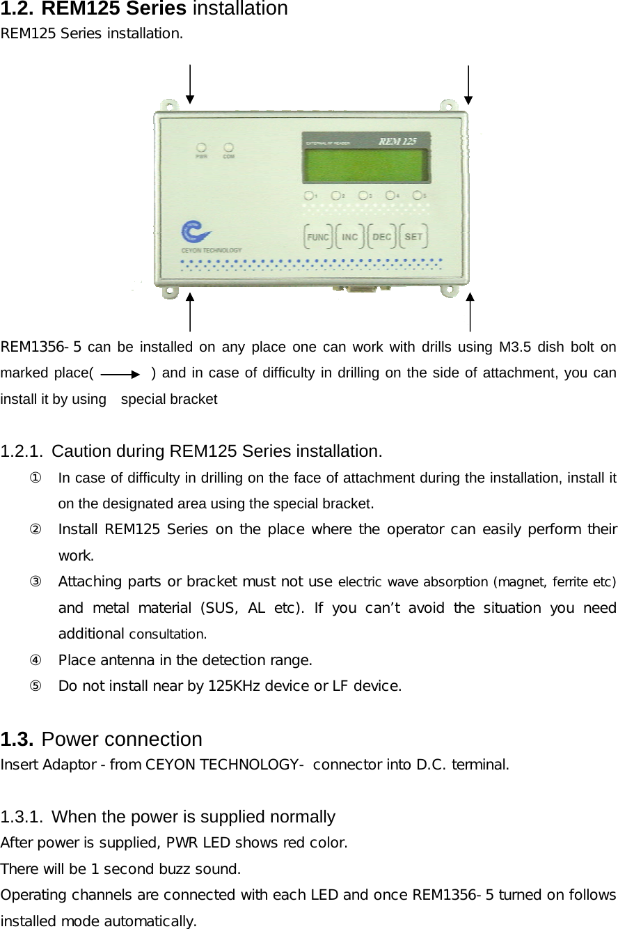
User Manual
Discussion / Help
Navigation
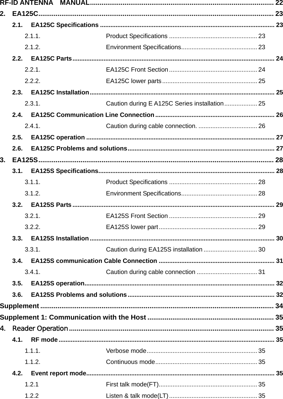
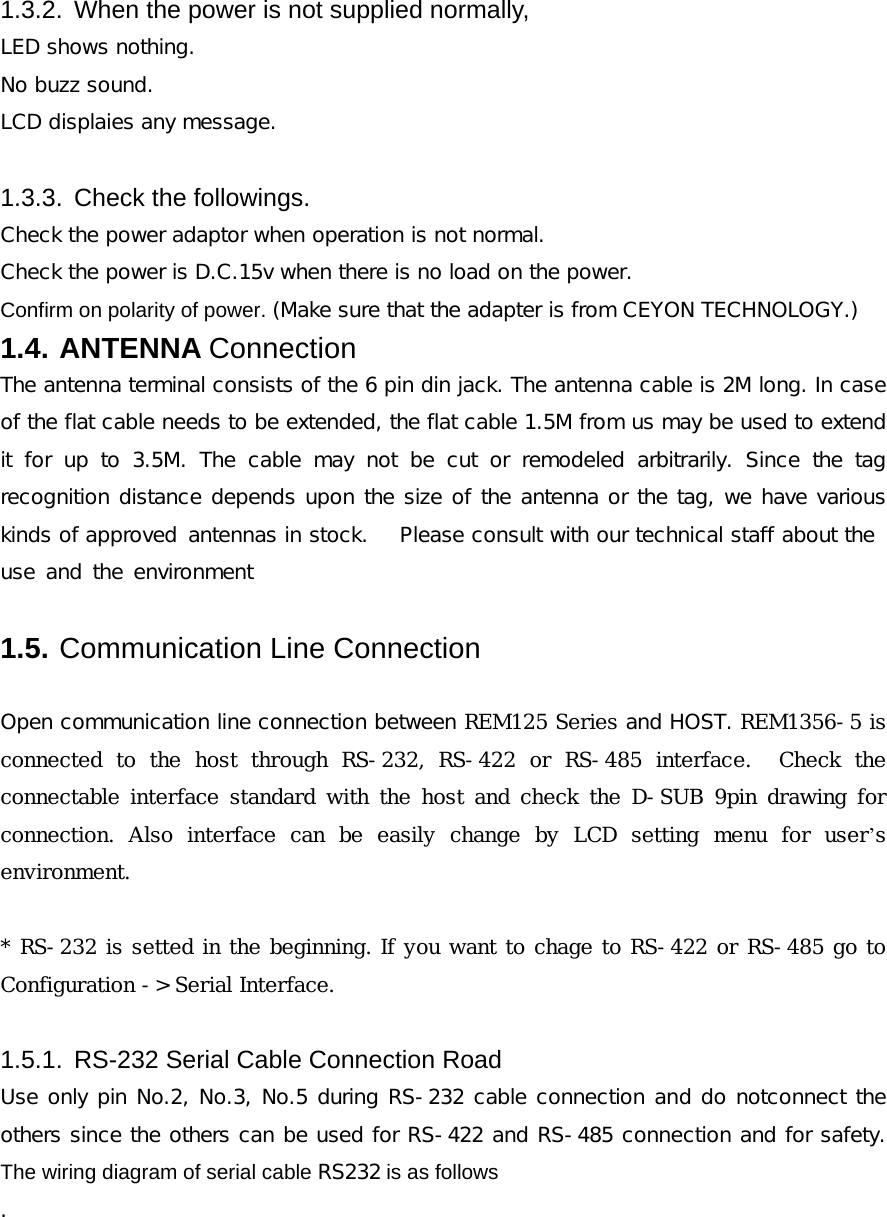
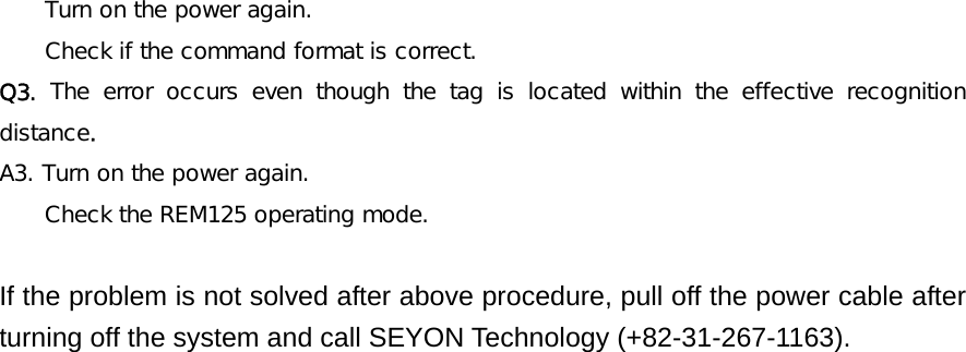
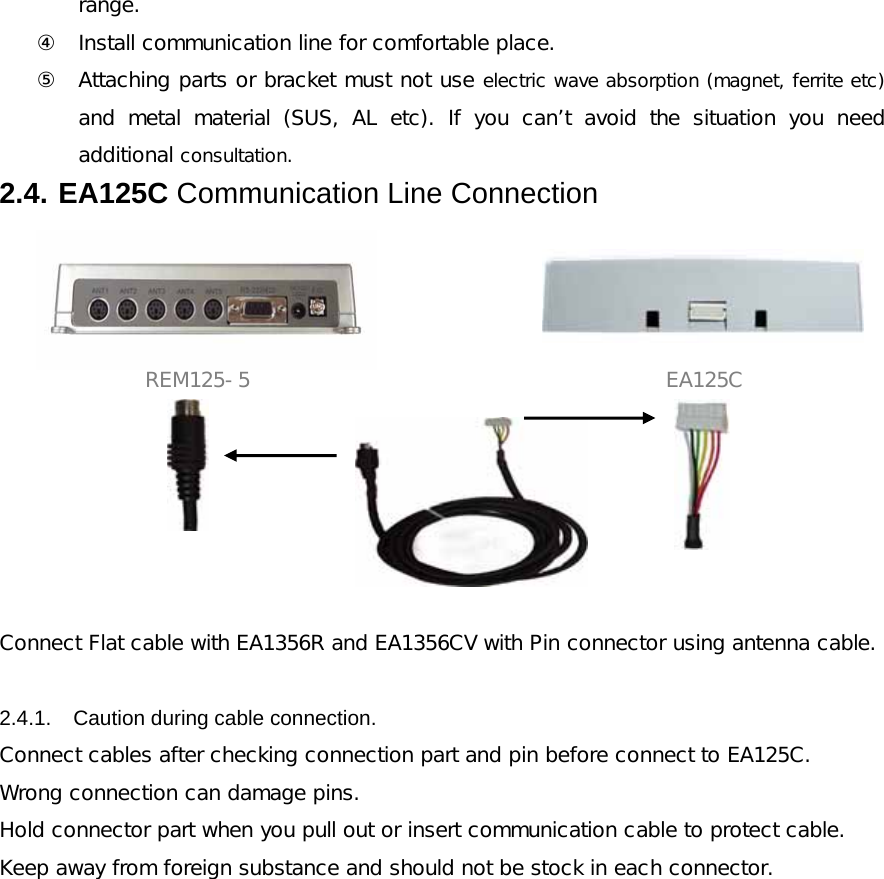
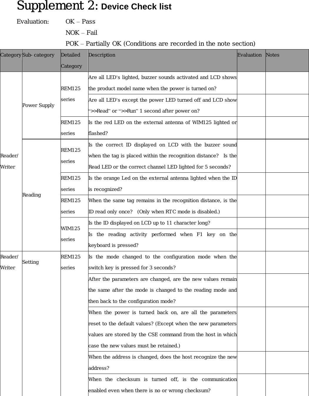
![1.6. Menu 1.6.1. REM125 Series Menu Tree >>RunREM125-5Ceyon Technology>>ConfigurationTest>>ConfigurationReader AddressReader Address>> Addr. : 01>>ConfigurationRF ChannelRF Channel>> Rfch5 : OnRF Channel>> Rfch4 : OnRF Channel>> Rfch3 : OnRF Channel>> Rfch2 : OnRF Channel>> Rfch1 : On>>ConfigurationSerial InterfaceRS-422>> RS-422Serial Interface>> RS-485Serial Interface>> RS-232>>ConfigurationBau d r at e Serial Interface>> 19200bpsSerial Interface>> 9600bps>>ConfigurationBuzzer ON/OFFBuzzer ON/OFF>> On>>ConfigurationRF Scan WeightRF Scan Weight>> 03>>ConfigurationMake DefaultMake Default>> Press <SET>Channel [1]Channel [2]Channel [3]Channel [4]Channel [5]Menu Tree REM125 SeriesFuncVar iation : I nc or DecConfirm : SetFuncFuncFuncInc or DecSetFuncFuncFuncFuncFuncFuncFuncSetSetSetSetSetSetSetVariation : Inc or DecConfirm : SetVar iation : I nc or DecConfirm : SetVariation : Inc or DecConfirm : SetOn/Off toggle : Inc or DecConfirm : SetVariation : Inc or DecConfirm : SetDefault : SetVariation : Inc or DecCurrent Channel Test : SetApply POWERFuncSetInc or DecInc or DecInc or DecInc or DecInc or Dec LOCK is setted in the run mode. To change the lock setting push FUNC key for 3 sec after buzz sound it will be unlocked.](https://usermanual.wiki/Ceyon-Technology/REM125-5/User-Guide-676914-Page-13.png)
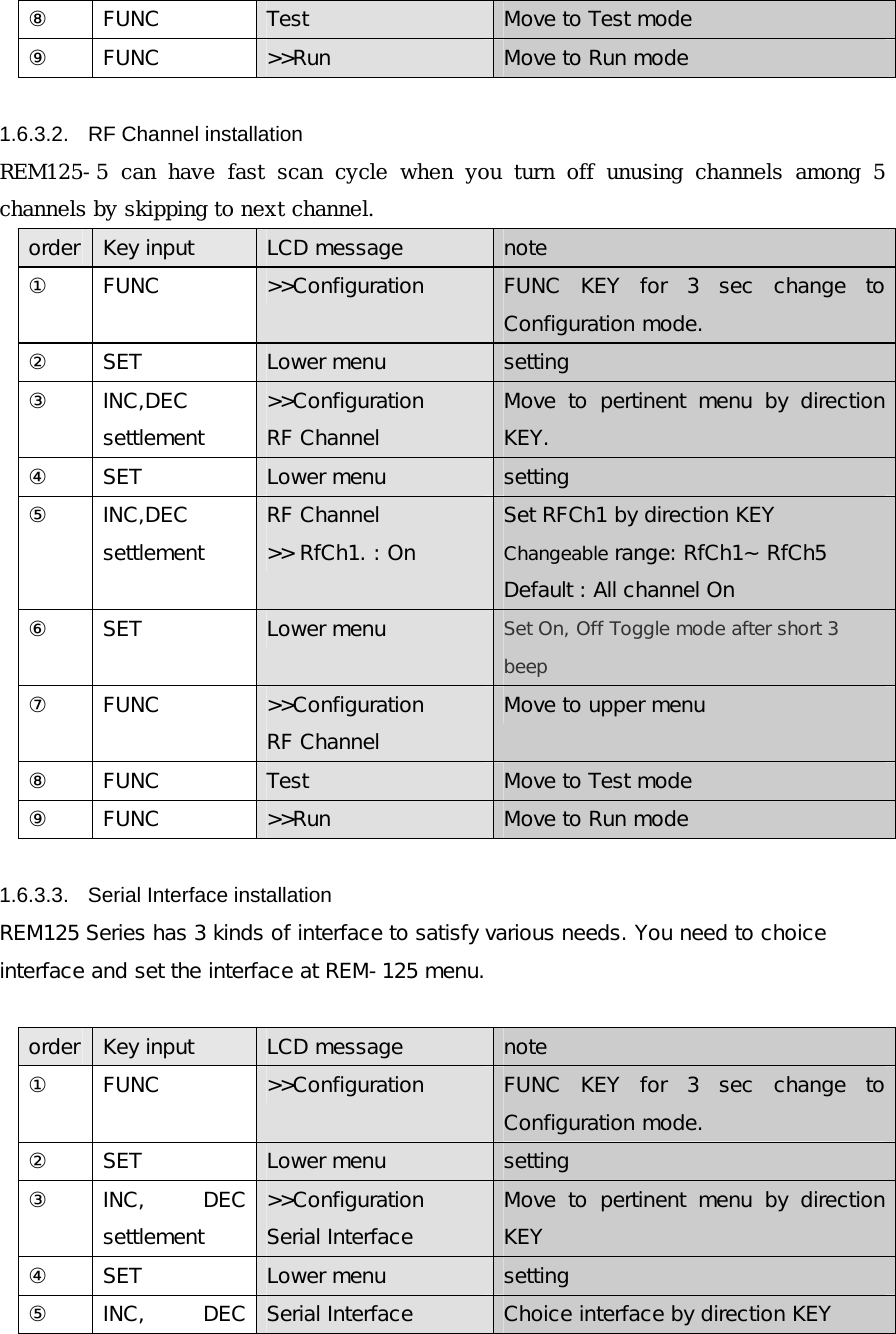
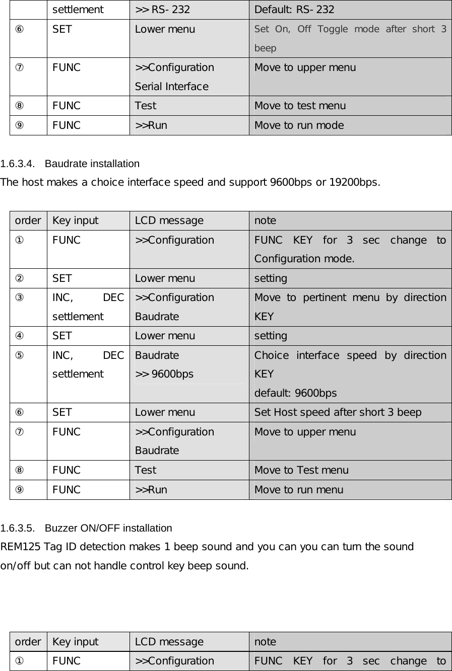
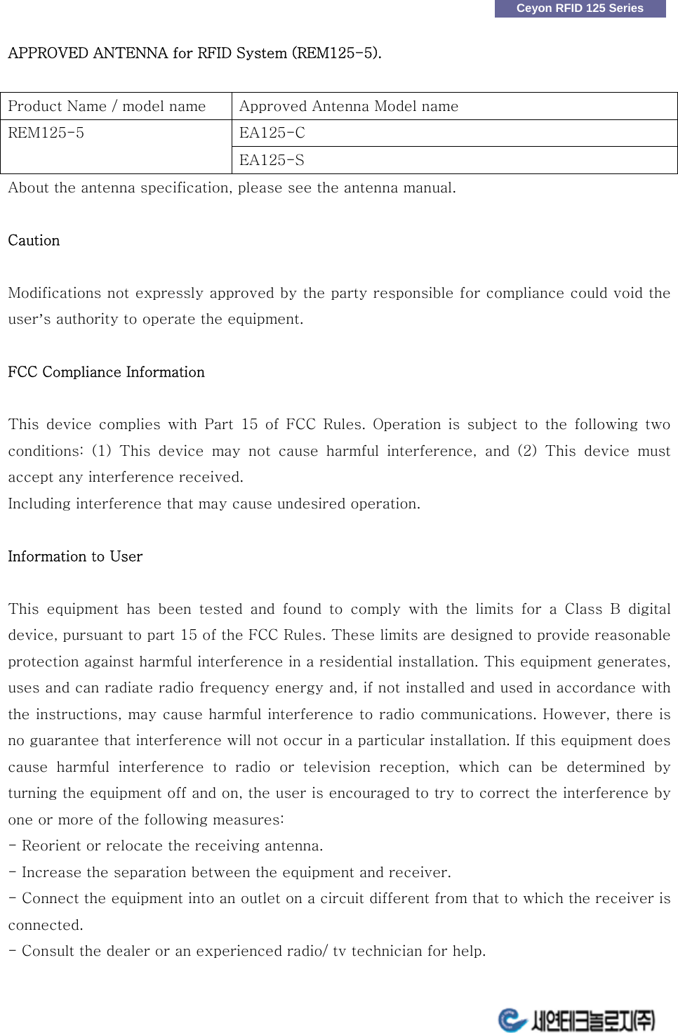
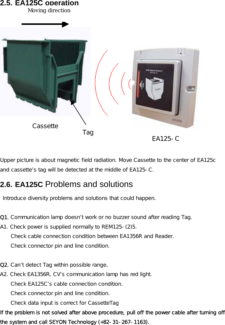
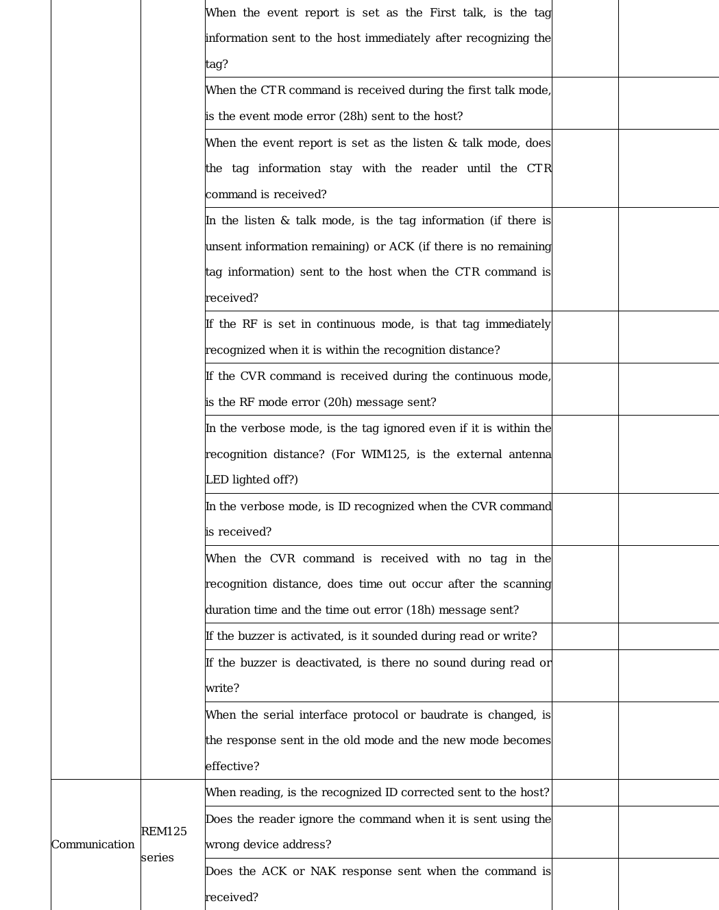
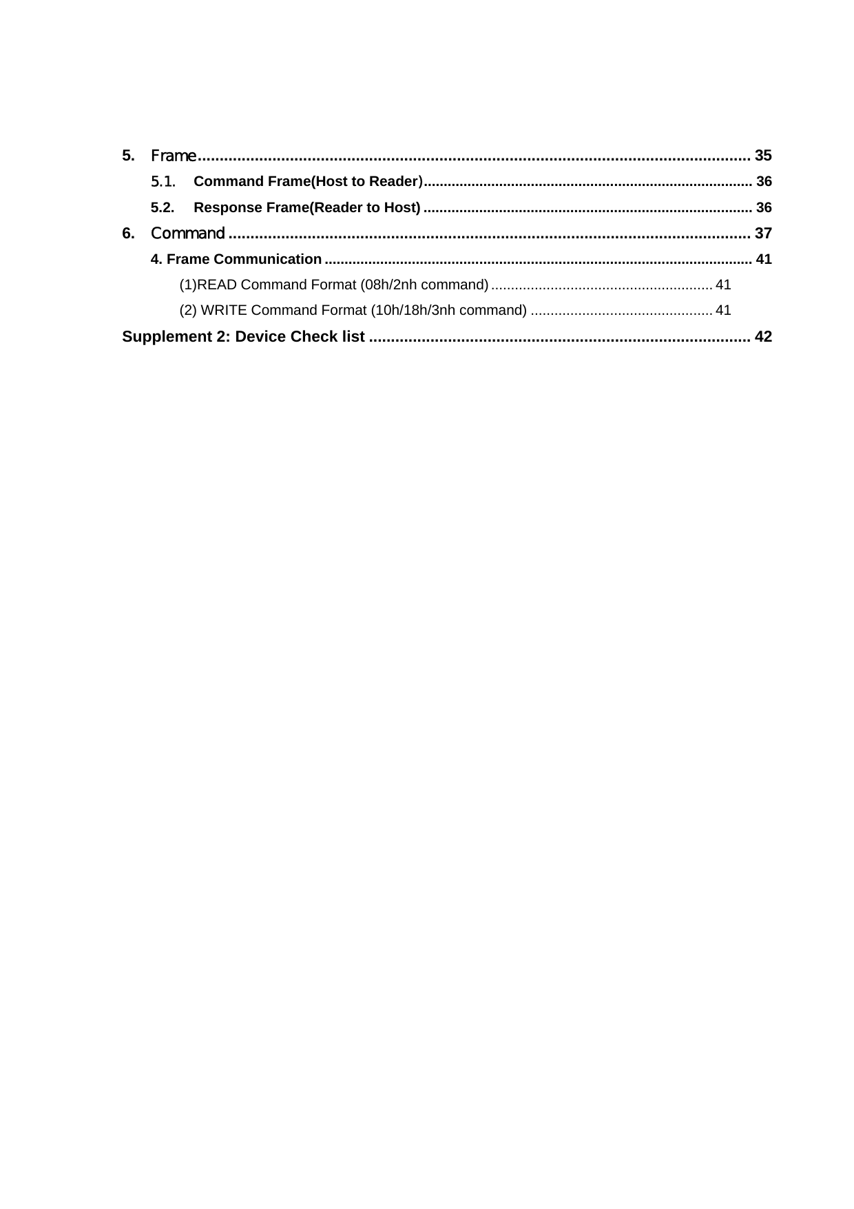
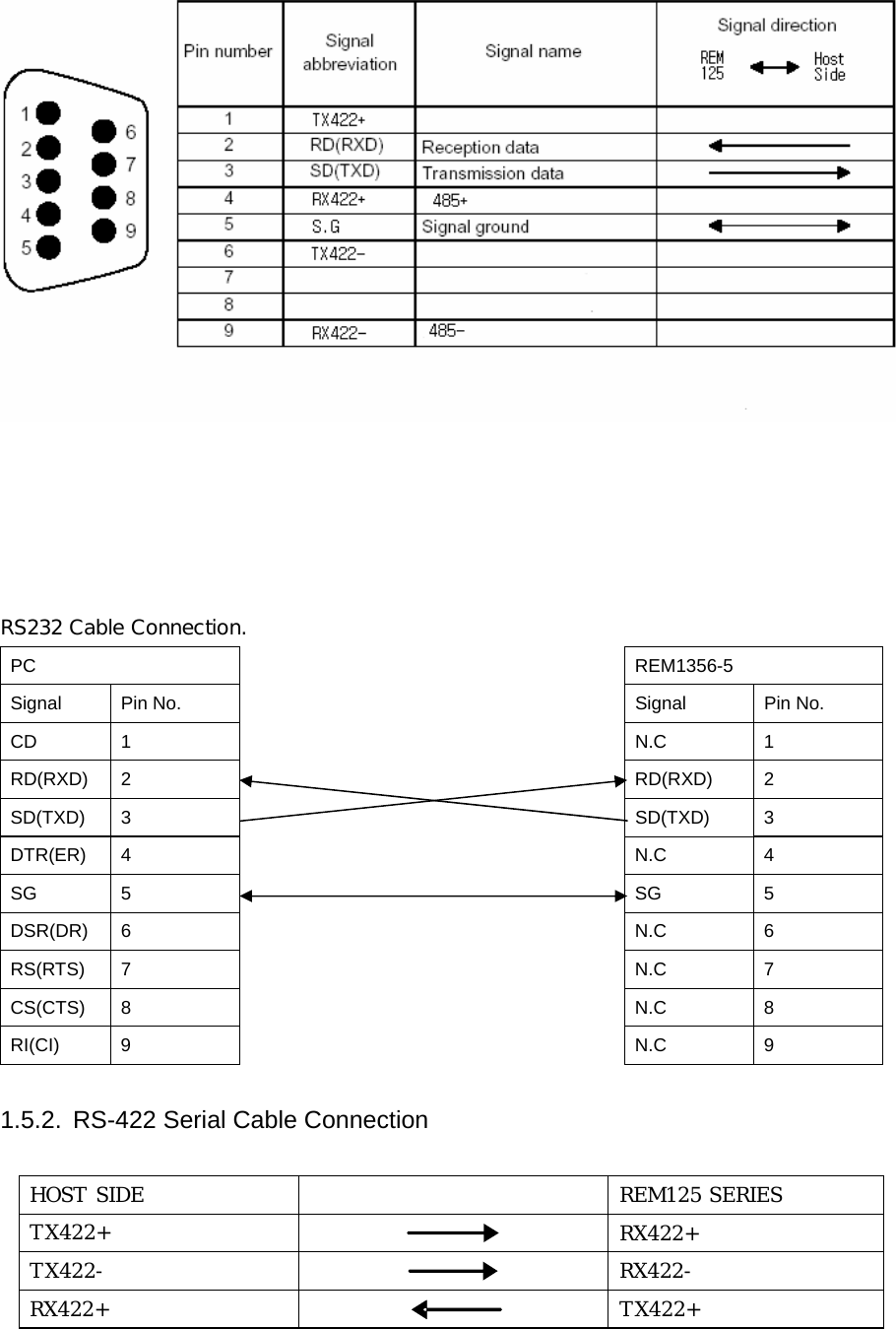
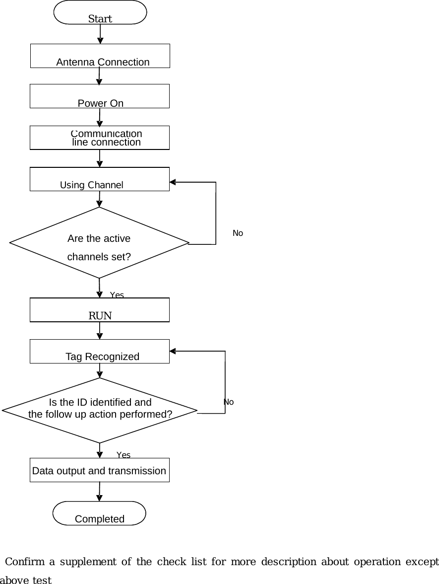
![order Key input LCD message note ① FUNC >>Configuration ② SET Lower menu setting ③ INC,DEC settlement >>Configuration Make Default Move to pertinent menu by direction KEY ④ SET Make Default >> Press <Set> Back to default mode ⑥ FUNC >>Configuration RF Scan Weight Move to upper menu ⑦ FUNC Test Move to Test menu ⑧ FUNC >>Run Move to run mode 1.6.4. REM125 Series Test (Trial mode) Checking operation condition before actual operation order Key input LCD message note ① FUNC Test Move to FUNC key ② SET Lower menu setting ③ INC,DEC settlement Channel [1] Move to pertinent menu by direction KEY Move to Testing RF CHANNEL ④ SET Channel [1] K60T0031 Send reading order Receive data normally ⑤ FUNC >> Run Move to run mode 1.7. Host Communication REM125 Series allows transmission/reception of the Tag ID and device setting from the host. For the type and standard of communication with the host, please refer to the attached protocol. 1.8. Recognition Test The following diagram shows the normal process flow from power on to tag ID recognition. Make sure that the system operates according to the diagram before actual use.](https://usermanual.wiki/Ceyon-Technology/REM125-5/User-Guide-676914-Page-18.png)
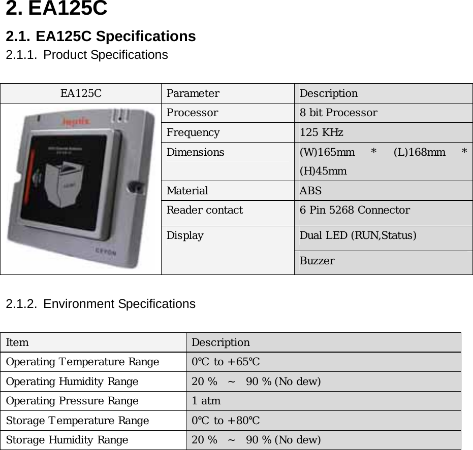
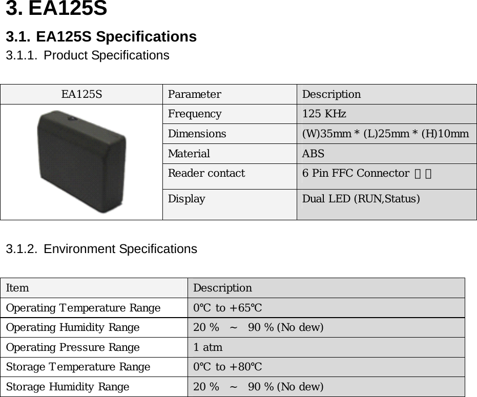
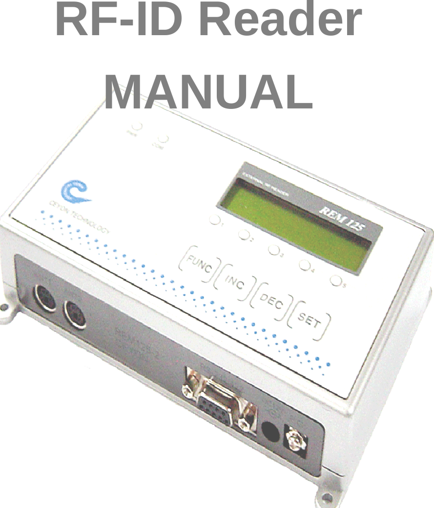
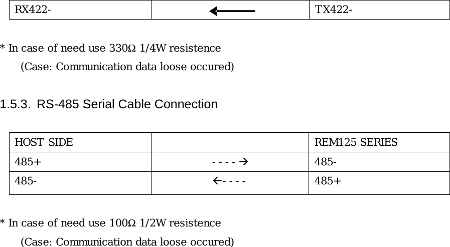
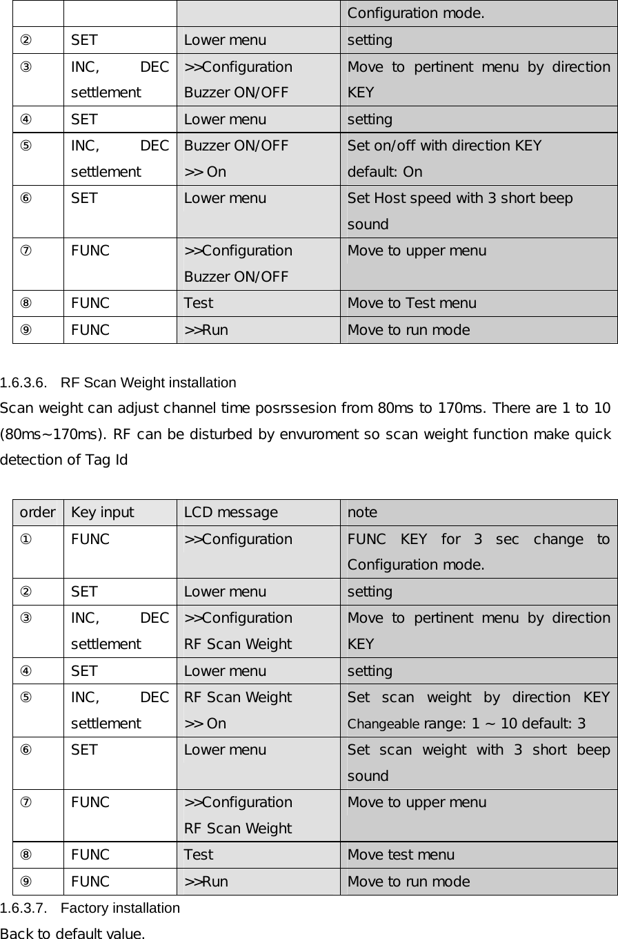
![1.9. Problems and solutions Introduce diversity problems and solutions that could happen.. 1.9.1. Power-related problems Q1. After connecting the power connector, LED isn’t on A1. When this problem occurs, check the followings. Check the equipment of the power supply. (DC12V / 1A ) Remove the cable from power input port and after 10 seconds reconnect it and restart REM125. 1.9.2. Problems on the connection between the networks Q1.When the connection between the host and REM125 cannot be made. A1. When this problem occurs, checks the followings. Check again the connection status of all kinds of cables connecting the host and REM125. Also check if using the private cable or not. Check the operational status of the host and REM125. . Q2. The connection between ANTENNA and REM1356-5 cannot be made. A2. When this problem occurs, checks the followings. Check again the connection status of all kinds of cables connecting the REM1356-5and ANTENNA. Also check if using the private cable or not. Check the operational status of REM134and ANTENNA. 1.9.3. Operation Related problems Q1 The system is not functioning normally . A1. Check the communication line is properly connected. Check if the power is normally supplied. Check LCD display Channel[!] at test mode * [!]means atenna adress Q2. . The system does not function normally even after the power and communication are connected properly. A2. Check if the proper cable is used. Check the address is setted corrected.](https://usermanual.wiki/Ceyon-Technology/REM125-5/User-Guide-676914-Page-20.png)