Chongqing Xiegu Technology X5105 HF+50MHz transceiver User Manual X5105 Instruction Manual
Chongqing Xiegu Technology Co.,Ltd. HF+50MHz transceiver X5105 Instruction Manual
UserManual.wiki
>
Chongqing Xiegu Technology
>
X5105 User Manual
Users Manual
Navigation menu
Upload a User Manual
Namespaces
Wiki Guide
HTML
PDF
Info
Views
User Manual
Discussion / Help
Navigation
![3 1 X5105 Specifications Basic Specifications Frequency range: Receive: 1MHz-55MHz-Transmitting: 160 meters -6 meters (Amateur band only) Operating mode: A1A(CW),A3E(AM),J3E(USB/LSB),F3E(FM) minimum frequency stepping: 1Hz Antenna impedance: 50Ω Operating temperature range: -10℃ ~ +60℃ Frequency stability: after turn on the radio 1-60 minutes is ± 2ppm, @25℃:1ppm/hour supply voltage: normal: 13.8VDC + 15%, negative grounding Operating voltage: 9.0-15.0VDC, negative grounding Current consumption: receive: 660mA@ Max transmit: 2.5A@ Max Battery capacity: 3800mAh @12V Dimensions: 160*100*46mm[does not include protrusion] Weight: 0.94Kg[host only] Transmitter parameters Transmitter power:5W(SSB/CW/FM),1.5W(AM carrier), @13.8VDC Modulation mode: SSB balanced modulation/AM low level amplitude modulation/FM Variable reactance frequency modulation FM Maximum frequency swing: ±5kHz spur reduction: -45dB Carrier suppression: >40dB Sideband spurious: >50dB SSB frequency response: 400Hz-2800Hz(-6dB) Microphone impedance: 200-10k(conventional 600Ω)](https://usermanual.wiki/Chongqing-Xiegu-Technology/X5105/User-Guide-3598702-Page-3.png)
![6 Charging and maintenance of internal battery X5105 has a built-in 5000mAh battery pack. When the external power supply is not connected, the battery pack supplies power to the X5105, when the X5105 is connected with an external power supply, the circuit inside the machine automatically switches to the external power supply. Charging method: 1 In the menu, select [CHG] option, start charging function. 2 The external power supply voltage is set between 13.5V-14.0V and the power supply is connected to the X5105 external power supply. The host will automatically start charging. 3 Charging time is 10 hours. By then, the charge will automatically stop. When the battery is powered for X5105, when the battery power is about to run out, the power indication sign on the upper right corner of the screen is displayed as . At this point, the X5105 should be charged or switched to an external power supply. During the charging process, the casing of the machine has a slight fever. Normally, the lifetime of the internal battery is about 4-5 years. Please replace the battery when the battery has a noticeable capacity drop or charge fails. When the X5105 is connected to an external power source, and when the X5105 is in the transmitting state, it is strictly forbidden to disconnect the power supply so as not to damage the power management chip. Please turn off the power immediately when the machine shell is very hot near the battery, and put the equipment in a safe and ventilated place. After confirming the safety situation, please contact us for proper handling.](https://usermanual.wiki/Chongqing-Xiegu-Technology/X5105/User-Guide-3598702-Page-6.png)
![7 2 Description of equipment 2.1 Front panel button function ① Power button Press this button for a second to turn on or turn off the radio. ② Mode button With this key, you can change the mode of operation and will cycle in the following mode: [LSB-USB-CW-AM-FM] ③ PRE/ATT button With this key, the preamplifier or pre attenuator will be turned on or be turn off in the following states: [PRE=ON--ATT=ON--PRE/ATT=OFF] ④ RIT button With this key, the receive frequency adjustment function is turned on or turn off. ⑤ NB button With this key to turn on or turn off the NB function. ⑥ MENU button With this key, you can switch the current display of the multi-function menu. ⑦ -⑩Multifunctional menu button Press these four buttons to turn on or off the corresponding function displayed on the menu area on the current screen. ○11 Major tuning knob The main tuning knob of X5105, can be used either for frequency regulation or for menus. ○12 ATU button When the key is pressed for a short time, the automatic antenna tuner will be connected to the antenna port, by pressing this button for a long time, the automatic antenna tuner](https://usermanual.wiki/Chongqing-Xiegu-Technology/X5105/User-Guide-3598702-Page-7.png)
![8 will be started. ○13 Po button With this key, and with the main tuning knob, the power of the transmitter can be adjusted. The range of adjustment is from 0.5W-5W, stepping for 0.5W. ○14 A/B button With this key, you will switch between VFOA-VFOB. ○15 < button With this key, the current frequency step carries one bit to the left. ○16 > button With this key, the current frequency step carries one bit to the right. ○17 V/M button With this key, you can switch between VFO mode and MEMO mode. ○18 Up button With this key, X5105 can be switched to higher frequency bands. ○19 DN button With this key, X5105 can be switched to lower frequency bands. ○20 -button With this key, you can reduce current volume. ○21 +button With this key, you can increase current volume. ○22 PTT button Press and hold this button, X5105 will go into the transmit state. ○23 LOCK button If you press this button for a short time, you will lock all buttons and knobs on the panel; By pressing this button for a long time, you can set the backlight on / off. Status indicator A [T/R] B [DATA] C [LINK] Transmit/Receive switch indication Data indication Peripheral connection indication Indicator color description: A T/R indicator When the X5105 is in receiving mode, the indicator light is green. When the X5105 is in transmitting mode, the indicator light is red.](https://usermanual.wiki/Chongqing-Xiegu-Technology/X5105/User-Guide-3598702-Page-8.png)
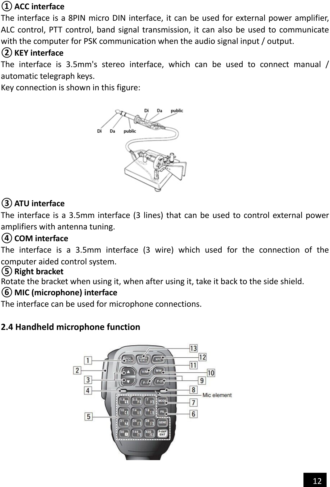
![13 1. LOCK button, you can lock the host button and the mouse button via this button, and press it again to unlock. 2. PTT button, transmitting control button. 3. Move up/down, adjustable frequency increase, subtraction, or selection of items in the menu. 4. Receiving / Transmitting indicator light, microphone operated indicator light. 5. Digital key 6. FIL button, built in filter selection. 7. MODE button, selection of host operating mode. 8. Function indicator lamp, No indication. 9. Function button, F1/F2 custom settings button. 10. MW button, store operation. 11. V/M button, frequency / channel switching. 12. XFC button, VFO-A / VFO-B switching. 13. CALL button, press this button for a long time to start the automatic antenna tuning in the host. 3 Operation 3.1 Turn on / off transceiver 1. Turn on the transceiver: just press for a long time 2. Turn off the transceiver: in the boot state, press the key for a long time. 3.2 Battery / voltage display 1. When the battery is powered by the built-in battery, the remaining battery power of the current battery will be displayed in the upper right corner of the display. 2. When using an external power supply, after switching the [VLT] menu, this position will display the voltage value of the current external DC power source that is currently connected to the transceiver. 3.3 Operating frequency band selection The frequency range of X5105 covers 0.5~54MHz. The amateur frequencies in this range are divided into multiple frequency bands and can be switched in a number of different ways. You can complete the equipment operation according to the operation instructions in this section.](https://usermanual.wiki/Chongqing-Xiegu-Technology/X5105/User-Guide-3598702-Page-13.png)
![14 Operation method: press DN or UP key to switch to the next or last operation band respectively. 3.5MHz 7.0MHz 10MHz 14MHz18MHz21MHz24MHz1.8MHz28MHz5.2MHz50MHz A. The opening of the 5MHz frequency band is based on the regulations of the country (or region) where it is located. B. Different versions of the machine have different frequency divisions, depending on their country (or region) regulations. C. VFO-A and VFO-B are two separate VFO modes, which can be set to different frequency bands. Please refer to the [VFO settings]. 3.4 Work mode selection Press the [MODE] button to switch between all modes in a fixed order. USB CWRLSBAMCWFM *VFO-A and VFO-B can be set to different operating modes in the same frequency band, thus realizing the different operation modes of "voice /CW". 3.5 Adjust the volume Adjust the output volume according to the volume plus and minus buttons.](https://usermanual.wiki/Chongqing-Xiegu-Technology/X5105/User-Guide-3598702-Page-14.png)
![15 When using the AF-OUT port of the ACC interface, adjusting the volume level will do the same for this port. 3.6 Regulated transmit power Press the [Po] transmit power setting button, you can set the transmit power. A. Press the [Po] button to enter the power setting state, and the screen will display the Po power set bar table. B. Rotate the big knob, set the power, step 0.5W. C. When the settings are complete, press the [Po] button again, save and exit the setup mode. When you do not understand the current state of the antenna, minimize the set transmit power value for the first time you use the X5105 transceiver. 3.7 Use the host PTT button X5105 comes with a PTT button, you can start the transceiver's transmission through this button. Operation method: A. Press this button to start the transmitting function. B. Speaking into the built-in MIC hole, can be completed communications. 3.8 Set operating frequency There are two ways to set the X5105 operating frequency, use the big knob to set the frequency, or use the multi-function mic to set the frequency. Operation method: A. Use large knob to set frequency Press the button [<] or [>], move the cursor of the frequency bit to the left or to the right, select the frequency of the desired step. Rotating frequency knob sets the frequency of the current step.](https://usermanual.wiki/Chongqing-Xiegu-Technology/X5105/User-Guide-3598702-Page-15.png)
![16 B. Use a multi-function microphone for frequency setting Press the [F-INP ENT] button on the cursor, and the X5105 enters the frequency setting. The cursor appears on the left of the frequency display bit. Enter the desired frequency value in turn, and then press [F-INP ENT] button again to complete the frequency setting. For example, set the current frequency to 51.050000MHz, and press the order as follows: First, press the [F-INP ENT] button. Please press the 51.050000 numeric key in turn. Once again press the [F-INP ENT] button to complete the settings. 3.9 Start the ATU (automatic antenna tuner) into the tuning function X5105 transceiver built-in an efficient automatic antenna tuner, which can help you easily complete the erection and debugging of the antenna. Press the [ATU] button for a long time, it will start the ATU auto tuning function. When the tuning is complete, the host will automatically return to the receiving state. 3.10 RIT (receive frequency trimming) Relative to the set frequency, the RIT function can set the offset value of the actual receiving frequency of the maximum ±5kHz. Operation method: A. Press [RIT] button to start RIT function. B. The rotating knob can change the receiver frequency in the range of ±5kHz. The screen has the corresponding area to display the frequency change value. C. If you want to turn off the RIT function, press the [RIT] button again. When the RIT function is enabled again, the last RIT setting will still be used. D. If you want to clear the RIT offset, in the RIT open state, turn the knob and set the offset to zero. If the frequency offset range more you want, you can use pilot frequency transceiver mode. Please refer to the VFO instructions for details.](https://usermanual.wiki/Chongqing-Xiegu-Technology/X5105/User-Guide-3598702-Page-16.png)
![17 3.11 Automatic gain control (AGC) By adjusting the proper recovery time parameters of the AGC automatic gain control system, the receiver can achieve the optimum state effect. Operation method: A. Switch to the second page menu, press the corresponding multi-function button to select the AGC function. B. The AGC function will be selected in the following order: When you select "AGC-AUTO", the CW mode is actually "AGC-FAST", in voice mode is "AGC-SLOW." If AGC-OFF is selected, the AGC system is turned off and the display of the S table is stopped. 3.12 Preamplifier / preamplifier (PRE/ATT) Pre amplifier (PRE) and pre attenuator (ATT) can improve the receiver's listening effect. When the signal is weak, the preamplifier can be switched on to increase the signal strength. When the signal is strong, the preamplifier can be switched on to reduce the signal strength. Of course, you can also choose to turn off the circuit unit so that the signal will by pass. Operation method: A. Press the [PRE/ATT] button to start the function. B. The switching sequence will follow the following loop: In the low frequency waves (less than 10MHz) operation, the preamplifier can be closed, then let signal in by-pass state, it will be more conducive to improve the receiving effect, And it can avoid the blocking of receiver caused by strong interference signal. Typically, when the S table is still changing, the preamplifier is not need to turned on. 3.13 Noise suppressor NB Noise suppressor can effectively eliminate some specific pulse type interference, especially the noise produced by the automobile ignition system, and can improve the receiving effect obviously. Operation method: AGC-FASTAGC-SLOWAGC-AUTOAGC-OFFATTPREOFF](https://usermanual.wiki/Chongqing-Xiegu-Technology/X5105/User-Guide-3598702-Page-17.png)
![18 A. Press the [NB] button, the screen appears corresponding prompt information, NB function is turned on. B. Press the [NB] button again, it will turn off the NB noise suppressor. * The NB function can only suppress the pulse noise of a specific type, and can not replace the NR noise reduction function. 3.14 Pilot frequency operation SPL and VFOA/B setting There are two independent VFO in X5105 transceiver, which can set different frequencies and modes respectively. Set the VFO reasonably, and with the menu SPL function, you can easily achieve pilot frequency transceiver operation mode. VFO settings: A. Press the [A/B] button, you can switch between VFO-A and VFO-B. B. When you switch to a certain VFO state, you can set the current VFO's working frequency, working mode, and so on. Pilot frequency transceiver operation method: A. First set the receiver frequency and mode (VFO-A). B. And then set the transmit frequency and mode (VFO-B). C. Press [MENU] button, switch to the first page menu, select the SPL function, it opens the pilot frequency transceiver working mode. *You can also make full use of VFOA/B to set different frequencies or modes, so double frequency monitoring can be achieved via real-time switching. 3.16 VFO mode /MEMO mode (V/M) setting Transceiver can switch between VFO mode and MEMO mode, and realize flexible operation mode. Operation method: A. Press the [V/M] button, you can switch between the VFO mode and the MEMO mode.](https://usermanual.wiki/Chongqing-Xiegu-Technology/X5105/User-Guide-3598702-Page-18.png)
![19 B. In the current mode, press the [V/M] button, and then switch to another mode. 3.17 Lock button operation The lock key (LOCK) can avoid the incorrect triggering of the transceiver and the microphone during outdoor operation. Operation method: A. Press the [Lock] button for a long time to start the lock. B. Press the [Lock] button for a long time again to turn off the lock. C. The icon appears on the corresponding area of the screen. 3.18 CW communication Operate with a hand key or an external keying device. Operation method: A. Insert the plug of the key (three wire) into the KEY interface on the right. B. Press the [MODE] button and switch mode to CW (or CWR). C. Press the [MENU] button for a long time, adjust the Menu #08 (CW DELAY) and set the delay time (default: 500ms). Press the [SAVE] button to save the new settings and exit the menu mode. D. Press the CW key, you can doing the CW communication. E. The tone of the CW sidetone can be adjusted by Menu #09 (CW TONE), as follows: ① Press [MENU] button for a long time to enter menu mode. ② Regulating Menu, #13 (CW, TONE). ③ Select the required tone, range from 200~2000Hz to adjustable, and the default](https://usermanual.wiki/Chongqing-Xiegu-Technology/X5105/User-Guide-3598702-Page-19.png)
![20 value is 800Hz. ④ After you complete the operation, press the [SAVE] button briefly, save the new settings and exit the menu mode. Using the built-in automatic key controller makes it easy to generate CW points, with the following methods of operation: ① Press the [MENU] button briefly, switch to the fourth page menu, and select the KEY function as KEY-A. ② Select the KSP function, rotate the frequency knob, adjust the automatic key rate, press the corresponding function button of KSP again, save and return. 3.19 Channel storage Regular channel storage: A. In VFO mode, parameters such as frequency, mode and advanced functional status are adjusted. B. Press the [MENU] button briefly, switch to the third page menu, select the V>M function, and start the channel editor. C. If the current channel is empty (not storing channel information), the channel number will flicker. Press the MW function key for a long time, after a "di" sound, the frequency information has been successfully stored on the channel. D. If the current channel has stored information, the channel number will not flicker. Rotate the knob to the nearest empty channel, press the MW function key for a long time, after a "di" sound, indicates that frequency information has been successfully stored on the channel. Adjust storage channel: A. If in VFO mode, press the [V/M] button on the panel, it will enter the channel mode. B. Turn the knob, you can switch the current channel, the channel number will change accordingly. Clear channel storage: A. In the channel mode, press the [MENU] button, switch to the third page menu, press the MC function key, start clear channel editing. B. At this point, the channel name or frequency value starts flashing. Press the MC button for a second, it will be heard twice "Di" sound, this indicates that the data in the current channel store is cleared and the channel number starts flashing, this indicating that the current channel number is empty. 3.20 Channel naming The stored channels can be named with the labels of letters and numbers to facilitate channel classification (e.g., work). You can do the editing in the menu mode as follows: A. Bring up the channel you want to name. B. Press the [MENU] button for a long time, enter the menu mode, rotate the knob, transfer Menu#23 (MEMTAG). C. Press the button [>] to start the tag edit. D. Rotate the knob, select the first letter (or number, symbol) you want to edit, and then press [>] to enter the next letter position.](https://usermanual.wiki/Chongqing-Xiegu-Technology/X5105/User-Guide-3598702-Page-20.png)
![21 E. Turn the knob again, select letters, numbers, characters, and press [>] to enter the next letter position. F. Repeat fifth steps until the tag editing is complete. Press the [MENU] key for a second, save the contents of the set tag and return to the normal operating state. In channel mode, press the [MENU] button briefly, switch to the third page menu, press the TAG function key, and display the label named for this channel. *You can press the TAG function key for a second, and you will transfer Menu #23(MEM TAG). 3.21 The menu system can personalize the transceiver and make it more in line with your habits. Operation method: A. Press the [MENU] button for a second and enter the menu mode. B. Press the [ V/A ] and [ A/B ] buttons to set the parameters you want. C. Rotate the knob to bring up the menu item you want to set. D. After the setting is complete, press the [MENU] key for a second, save the current setting and exit the menu mode. * In the above fourth steps, if you press the [QUIT] button briefly, you will not save the new settings and exit the menu mode. Menu system description Menu item function Set value default 01 Filter 1 Fc Filter 1 center frequency point (CW filter) 1M~100M 10.695M 02 Filter 2 Fc Filter 2 center frequency point (SSB filter) 1M~100M 10.695M 03 Filter 3 Fc Filter 3 center frequency point (AM filter) 1M~100M 10.7M 04 Filter 1 Bw Filter 1 bandwidth (CW filter) 100Hz~100kHz 500 05 Filter 2 Bw Filter 2 bandwidth (SSB filter) 100Hz~100kHz 2400 06 Filter 3 Bw Filter 3 bandwidth (AM filter) 100Hz~100kHz 6000 07 RF Gain Receive RF gain 10~100% 65% 08 CW Delay CW T/RX switch delay 0~10000mS 500mS 09 CW Tone CW transmit side tone frequency 200Hz~2000Hz 800Hz 10 SSB Tx Lv SSB transmit modulation level 10~100% 50% 11 AM Tx Lv AM transmit modulation level 10~100% 50% 12 NFM Tx Lv NFM transmit modulation level 10~100% 100% 13 SSB Rx Lv SSB receive audio gain 10~100% 50% 14 AM Rx Lv AM receive audio gain 10~100% 50% 15 NFM Rx Lv NFM receive audio gain 10~100% 40% 16 BackLight Backlight brightness 0~100% 100% 17 Ref Clock Reference clock frequency 1M~100M 26M 18 OutBand EN Out of band permit 0~1 0 19 NFM Tx IF NFM transmit if 1M~100M 10.697M](https://usermanual.wiki/Chongqing-Xiegu-Technology/X5105/User-Guide-3598702-Page-21.png)