Chongqing Xiegu Technology XPA125B Linear Power Amplifier User Manual
Chongqing Xiegu Technology Co.,Ltd. Linear Power Amplifier
UserManual.wiki
>
Chongqing Xiegu Technology
>
XPA125B User Manual
User manual
Navigation menu
Upload a User Manual
Namespaces
Wiki Guide
HTML
PDF
Info
Views
User Manual
Discussion / Help
Navigation
![XIEGU COMMUNICATIONS 3.1.4 Connection method between XPA125B and other QRP radio If you want to start the XPA125B power amplifier and put it into the transmit mode, you need to set the PTT port to a low level [level≤0.1V]. If the PTT output signal of the transceiver is at high level, the high level needs to be converted into a low level, and then input to the XPA125B [ACC-PTT] port. Pin 2 of the XPA125B ACC port is the PTT input port In order to achieve automatic band switching, the corresponding band voltage is needed. XPA125B band control voltage information is as follows. BAND LEVEL(mV) 230 460 690 920 BAND LEVEL(mV) 1380 1610 1840 2070 BAND 50.0 MHz ---- ---- ---- LEVEL(mV) 2530 ---- ---- ---- 1.8 MHz 3.8 MHz 5.0 MHz 7.0 MHz 10.0 MHz 14.0 MHz 18.0 MHz 21.0 MHz 24.0 MHz 28.0 MHz 1150 2300 ---- ---- 3.2 Procedure: 3.2.1 Using the power amplifier unit [PA unit] (ATU unit is set to BYPS) - - PressthePAkey,sothatthestateoftheamplifieris[INUSE]. If your connected transceiver is an X108G or X5105, please set the output power to 5 W. If you are using any other QRP transceiver, please set the output power to 1 W. Set your transceiver to CW mode, press the CW key to transmit, andtheXPA125B amplifier will be activated. Theoutput powerofthe XPA125B canbe adjustedby adjusting theoutputpowerofthe connected transceiver. - - - 9](https://usermanual.wiki/Chongqing-Xiegu-Technology/XPA125B/User-Guide-3941874-Page-9.png)
![XIEGU COMMUNICATIONS Warning: 1. Do not allow the maximum output power of the amplifier to exceed 120 W. 2. Using the XPA125B at high power levels for extended periods can lead to overheating and potential damage to the PA stage. 3.2.2 Band switching - - - Youcanswitchbetweenthetwomodesof[AUTO-MANUAL] via this key. If you want to connect the XPA125B to an X108G or X5105, please setXPA125B to[AUTO]mode. If you want to connect the XPA125B to other devices, please set XPA125B to [MANUAL] mode and manually switch to the desired frequency band. Manual switching of frequency bands follows this order: 160m→80m→60m→40m→30m→20m→17m→15m→12m→10m→6m 3.2.3 Using the automatic antenna tuner unit [ATU] (PA unit is set to BYPS state). - Pressthe [ATU]buttonso thatthecurrentstateof theamplifier is [INUSE]. SetthetransceivermodetoCW& settheoutputpowerto5 W. - - Press the CW key to transmit, and the XPA125B PA amplifier stage will be activated. The XPA125B ATU unit will start, the screen will display [TUNE]. - - Iftuningissuccessful,thescreenwilldisplay[INUSE]. If tuningfails,thescreenwilldisplay[Fail]. If you need to re-tune, you can press the [ATU] button for two seconds to force the XPA125B ATU unit to start re-tuning. After successful tuning, switch the transceiver to the desired state for use. 10](https://usermanual.wiki/Chongqing-Xiegu-Technology/XPA125B/User-Guide-3941874-Page-10.png)
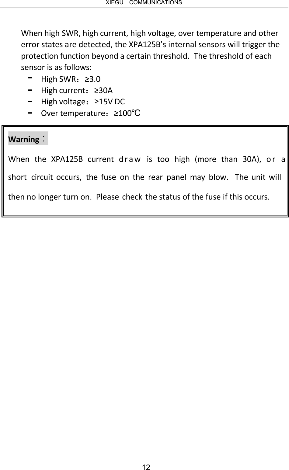
![XIEGU COMMUNICATIONS 3.2.4 Combined use of power amplifier + automatic antenna tuner - - Press the [PA] button so the current state of the PA unit displays [INUSE]. Pressthe[ATU]buttonsothecurrentstateoftheATUunit displays [INUSE]. - - Set the transceiver mode to CW, the output power to 5 W, and press the CW key. If the current SWR value is more than 3.0, the ATU unit will start tuningautomatically. Atthistime the PA unit will be disabled. If the current SWR value is less than 3.0, the ATU unit will start tuningautomatically,andthePAunitwill be activated. If the current SWR value is more than 3.0, and automatic tuning fails, the XPA125B will automatically switch to bypass mode and display this informationonthescreen. - - 3.2.5 Flexible configuration of PA unit and ATU unit The ATU unit and PA unit of XPA125B can be used independently of each other. You can therefore use the XPA125B as either an automatic antenna tuner or a separate power amplifier. You can also bypass both units, and your transceiver will then be connected directly to the antenna. 3.2.6 Protection and warning The XPA125B incorporates a variety of intelligent protection functions to ensure as far as possible the safety of the equipment in daily use. When the XPA125B enters an abnormal state, it will immediately enter protection mode and switch to bypass mode. 3.2.7 Remove protection and warning Release the PTT button. Protection will be disabled and the XPA125B will return to the receiving state. Warning messages are as follows: SWRI too high! (Input value of Idd too high! (Operating SWR is high) PIN too high! (High input power) current is too high) Vdd too high! (Input voltage is too high) SWRO too high! (Output value of Wrong band! SWR is high) (Filter error) PO too high! power) (High output Gain too low! Temp too high! (Operating temperature is too high) Efficiency too low! 11](https://usermanual.wiki/Chongqing-Xiegu-Technology/XPA125B/User-Guide-3941874-Page-11.png)