Cicor Deutschland 01MONILOG MONI LOG EnDaL smart User Manual 15 EnDaL smart UserMan
SMT&Hybrid; GmbH MONI LOG EnDaL smart 15 EnDaL smart UserMan
UserManual.wiki
>
Cicor Deutschland
>
01MONILOG User Manual
15_EnDaL_smart_UserMan
Navigation menu
Upload a User Manual
Namespaces
Wiki Guide
HTML
PDF
Info
Views
User Manual
Discussion / Help
Navigation
![EnDaL smart DEVICE DESCRIPTION OF MONI LOG® ENDAL SMART - 15 - 3.4 D E V I C E R U N T I M E A ND B A T T E R Y C H A N G E Device runtime The device runtime of the EnDaL smart depends on the set measurement parameters. Here, the interval setting of the GPS position determination is the key factor. The connection between device runtime and GPS or synchronous interval is illustrated in the following figure: Figure 1: Estimation of the device runtime in dependence on the synchronous interval 0100200300400500600110 100 1000runtime [days] Synchronous interval[min] Use with internal GPS-receiver Use with inclination measurement Use without any syncronous measurement](https://usermanual.wiki/Cicor-Deutschland/01MONILOG/User-Guide-2912624-Page-17.png)
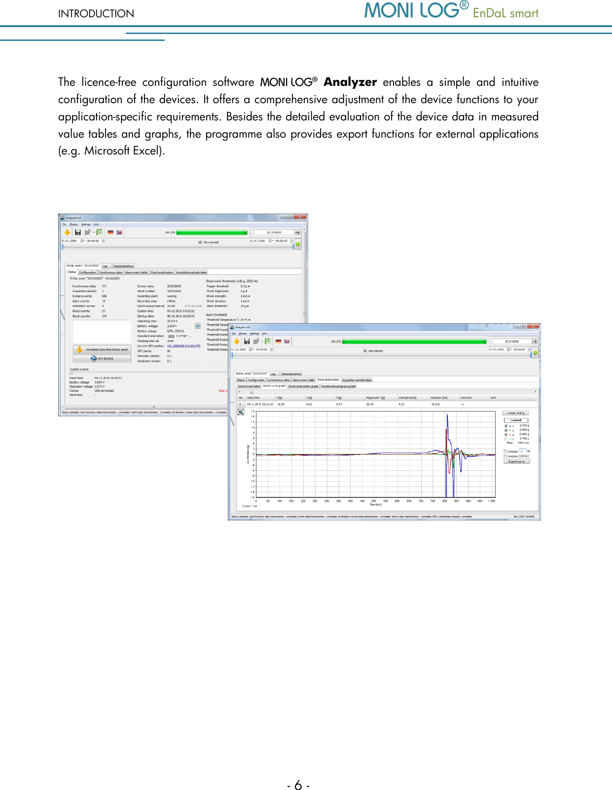
![PC SOFTWARE – MONI LOG® ANALYZER EnDaL smart - 20 - 4.2 G E N E R A L U S E O F T H E PC S O F T W A R E 4 . 2 . 1 E s t a b l i s h i n g t h e d e v i c e c o n n e c t i o n When the device driver is installed and a device is connected via USB, the connection will be established automatically as a rule upon start of the evaluation software. If the evaluation programme has already been active before plugging the device, move the mouse in the area [COM-Port] (Figure 3). The connection is established automatically. If you would like to connect a device at another COM-Port, click onto the USB symbol and select it in the selection window (see for this Figure 4). Figure 3: No connection select COM-Port Figure 4: USB connection window: currently connected to COM15 COM16 also available In case of connection problems: If no connection can be established to the device, select the Refresh button (blue double arrow) and disconnect the USB cable from the device. Afterwards, reconnect it with the USB cable.](https://usermanual.wiki/Cicor-Deutschland/01MONILOG/User-Guide-2912624-Page-22.png)