Cicor Deutschland 08MONILOG MONI LOG data link sensor User Manual UserMan
SMT&Hybrid; GmbH MONI LOG data link sensor UserMan
UserManual.wiki
>
Cicor Deutschland
>
08MONILOG User Manual
UserMan
Navigation menu
Upload a User Manual
Namespaces
Wiki Guide
HTML
PDF
Info
Views
User Manual
Discussion / Help
Navigation
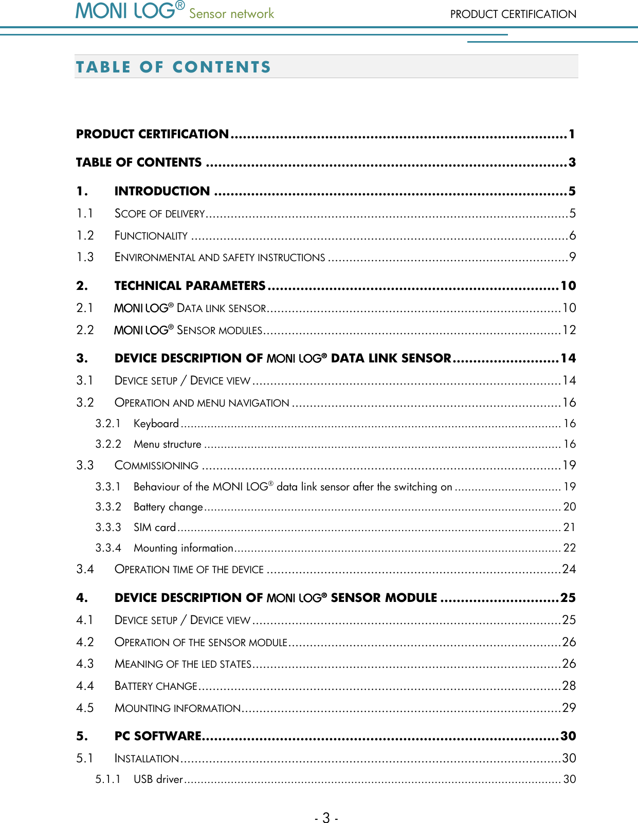
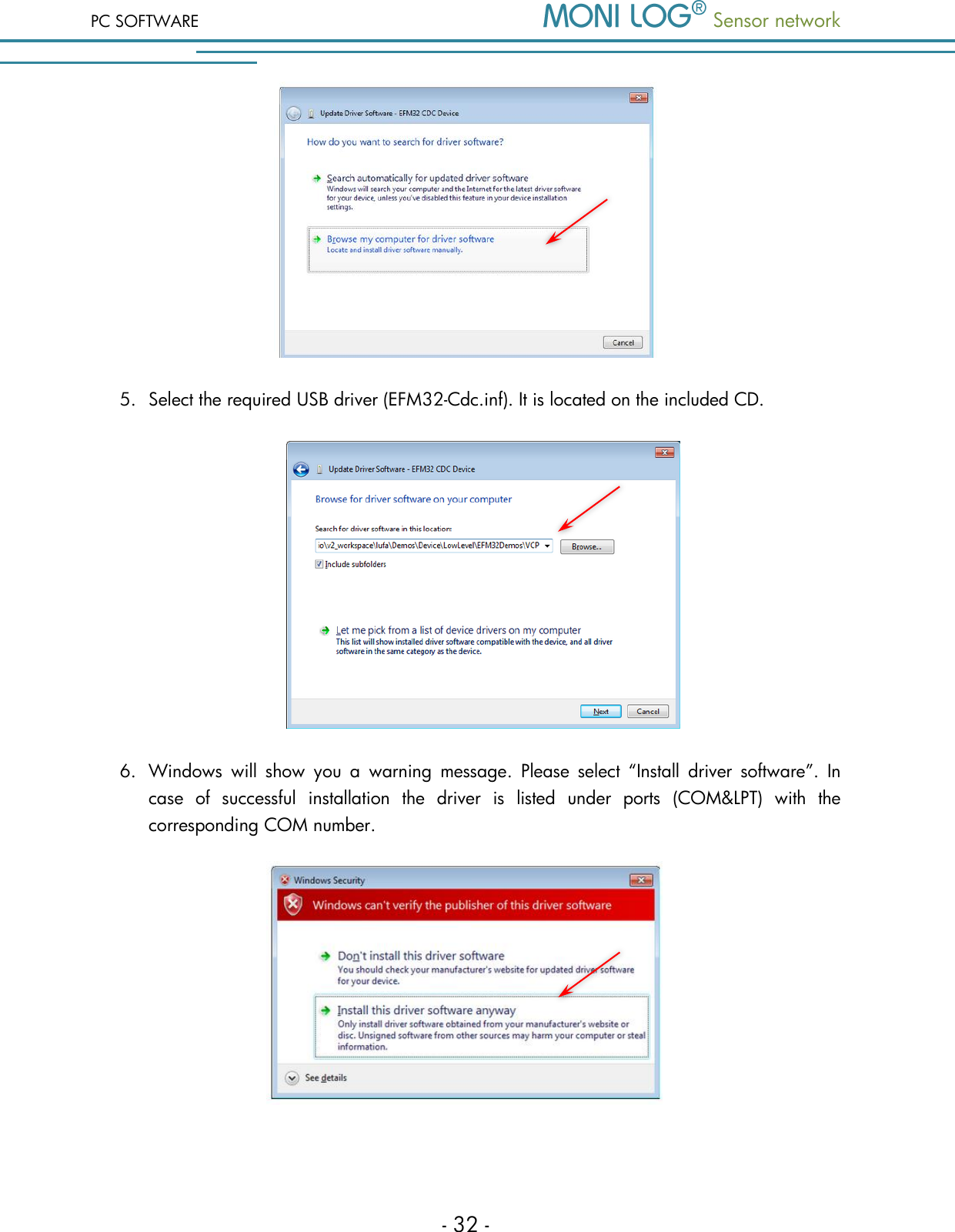
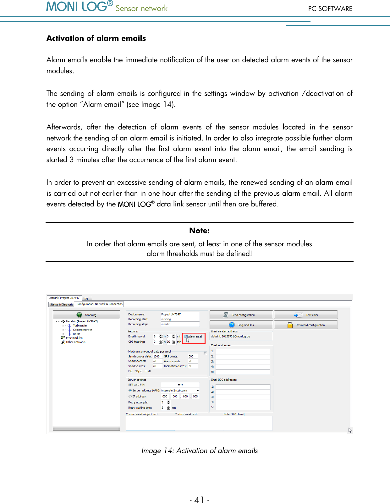
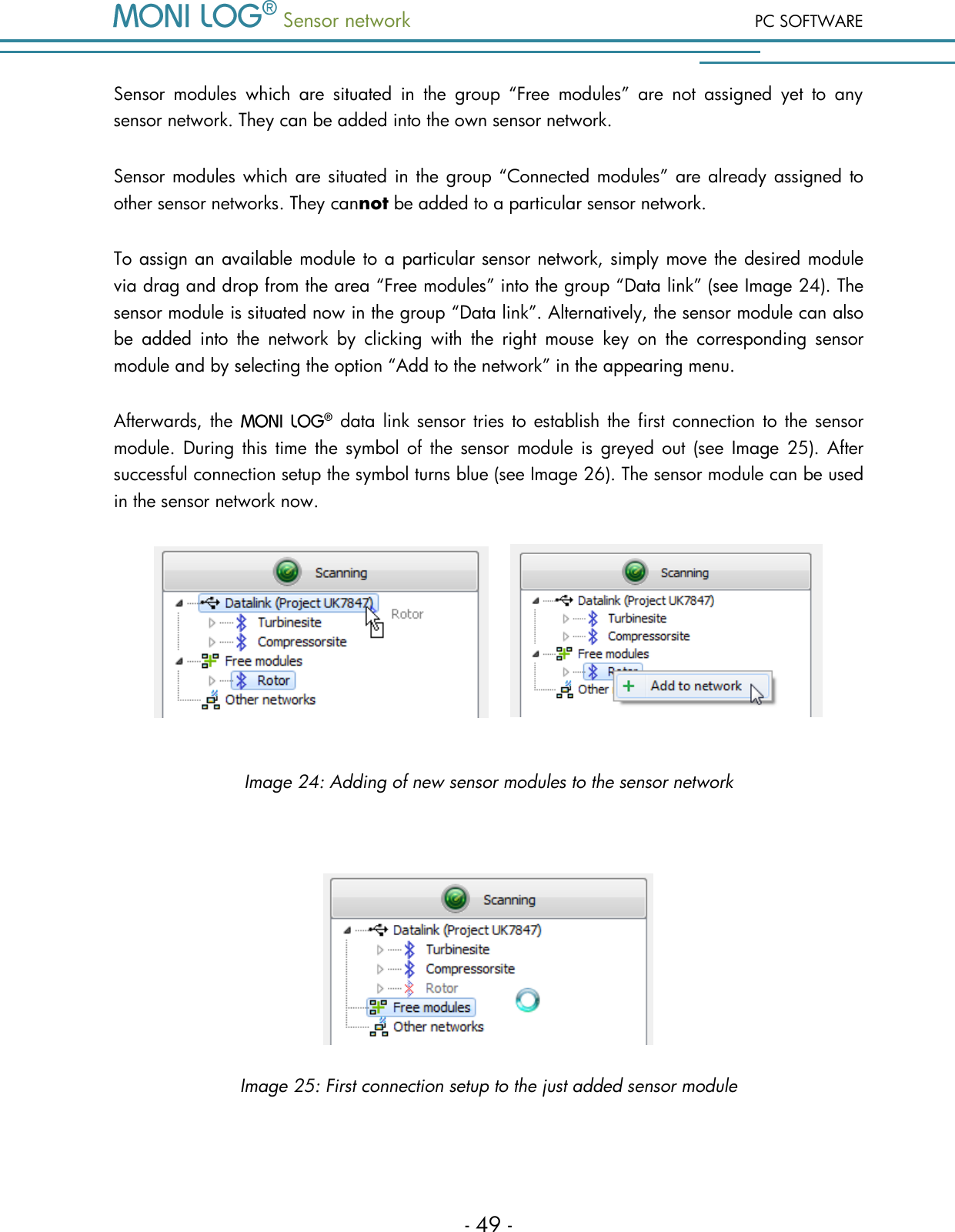
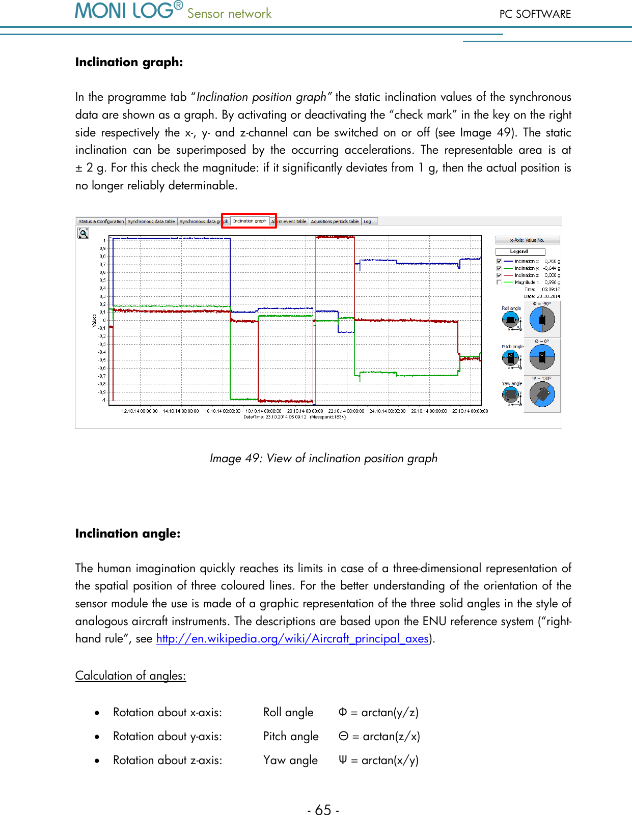
![Sensor network PC SOFTWARE - 33 - 7. The driver installation is completed, the USB interface can now be used. 5 . 2 G E N E R A L U S E O F P C S O F T W A R E 5 . 2 . 1 E s t a b l i s h i n g a d e v i c e c o n n e c t i o n If the device driver is installed, the connection, as a rule, will be automatically established upon the start of the evaluation software, if a device is connected via USB. If the evaluation programme has already been active before the plugging of the device, move the mouse in the area [COM-Port]. The connection is automatically established. If you would like to connect a device at another COM-Port, select it in the selection window (see for this Image 6). Image 6: USB connection window: left) no connection; right) connection established In case of connection problems: If the USB connection is not initiated correctly select the Refresh button (blue double arrow), disconnect the USB cable from the device and reconnect it.](https://usermanual.wiki/Cicor-Deutschland/08MONILOG/User-Guide-2662355-Page-35.png)
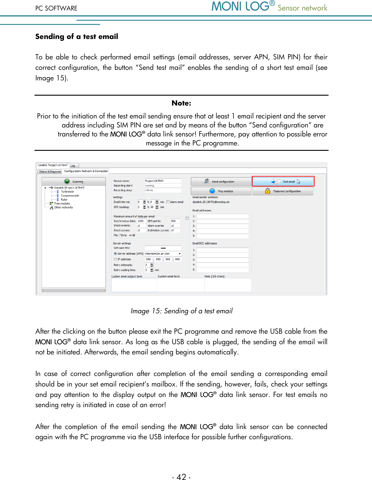
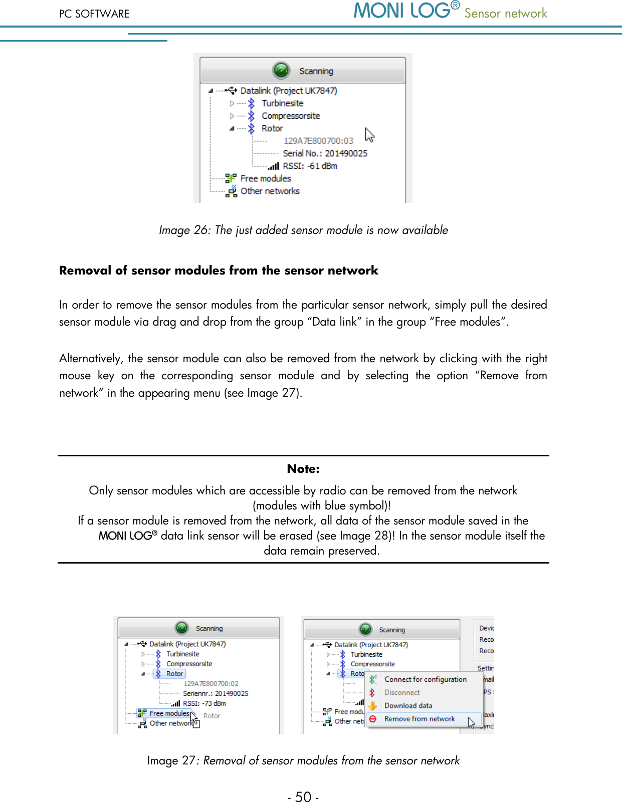
![Sensor network PC SOFTWARE - 69 - Image 54: Shock curves graph Shock recording: The shock recording begins, if the value of the acceleration exceeds the triggering threshold. The triggering threshold is configured internally by the device and depends on the set magnitude threshold (currently: triggering threshold = ½*magnitude threshold, minimum: 500 mg). This way, processes which lie chronologically before the actual exceeding of the magnitude threshold are also registered. A shock event is saved if the recording thresholds for shock magnitude, shock strength and shock duration are at least fulfilled. Image 55: Criteria for the shock recording Magnitude r exceeds the magnitude threshold (3 g) Channel exceeds the triggering threshold (1.5 g) Recording start Time [ms] Acceleration [g] Time :](https://usermanual.wiki/Cicor-Deutschland/08MONILOG/User-Guide-2662355-Page-71.png)
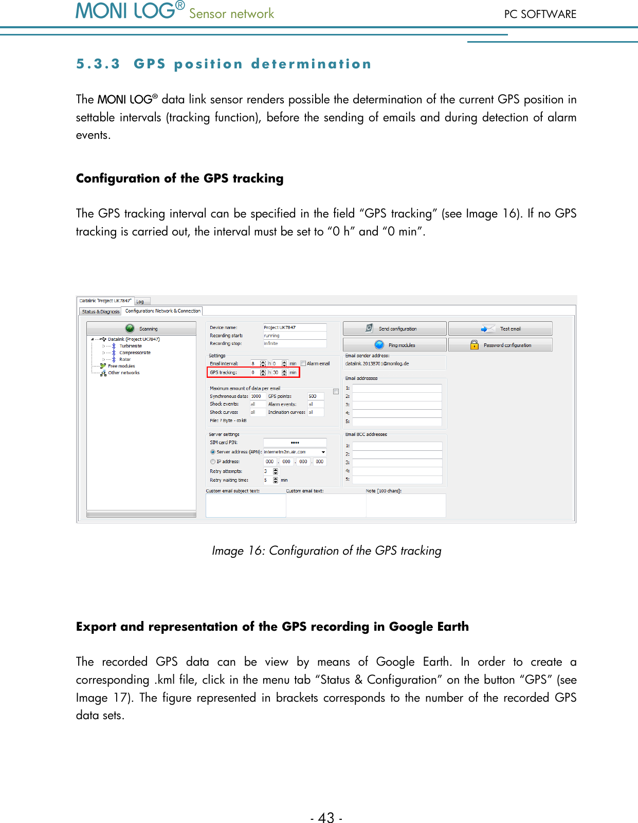
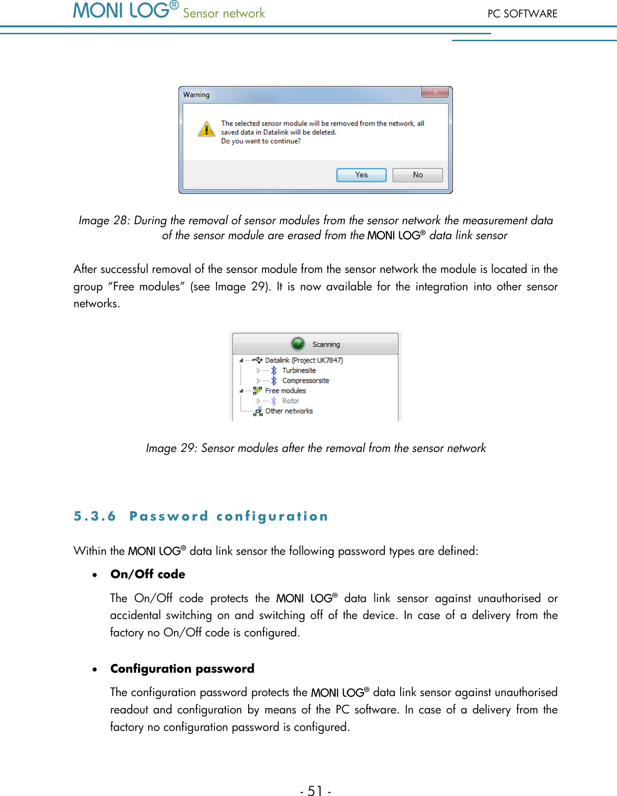
![PC SOFTWARE Sensor network - 70 - The largest single pulse within the scanning time of 1024 ms is considered as a shock event, which meets all set conditions (shock magnitude, shock strength, shock duration). A single pulse is deemed to be completed, if all three channels (x,y,z) are below 200 mg according to magnitude for more than 100 ms (fading condition). The shock pulses are compared with each other regarding their shock strength (corresponds to time integral over the course of the shock magnitude). The following should be explained on the basis of Image 56. The 1st pulse begins with the start of the recording and fades away again very quickly. The following 2nd pulse begins with the repeated exceeding of the triggering threshold (1). At point (2) all channels fall below the 200mg limit, however, no longer than 100 ms (3). At point (4) the fading condition is finally fulfilled and the 2nd pulse is completed. In over 200 milliseconds after that the 3d pulse is finally detected. Though the 3nd pulse shows the highest maximum amplitude, the 2nd pulse is the greatest with respect to the shock strength and is used here for the shock evaluation. Image 56: Shock curve with 3 single pulses Area: ± 200 mg 1. 2. 3. Triggering threshold > 100 ms > 200 ms 44 34 24 14 1 2 3 y z x Magnitude x-axis y-axis z-axis Image 57: Sensor module main axes for acceleration/inclination Time [ms]](https://usermanual.wiki/Cicor-Deutschland/08MONILOG/User-Guide-2662355-Page-72.png)