Cisco Systems 102075 Cisco Aironet 802.11n Dual Band Access Points User Manual Cisco Wireless LAN Controller Configuration Guide 1
Cisco Systems Inc Cisco Aironet 802.11n Dual Band Access Points Cisco Wireless LAN Controller Configuration Guide 1
Contents
- 1. User manual
- 2. Cisco Wireless LAN Controller Configuration Guide_1
- 3. Cisco Wireless LAN Controller Configuration Guide_2
- 4. Cisco Wireless LAN Controller Configuration Guide_3
- 5. Cisco Wireless LAN Controller Configuration Guide_4
- 6. Cisco Wireless LAN Controller Configuration Guide_5
- 7. Cisco Wireless LAN Controller Configuration Guide_6
- 8. Cisco Wireless LAN Controller Configuration Guide_7
- 9. Cisco Wireless LAN Controller Configuration Guide_8
- 10. Cisco Wireless LAN Controller Configuration Guide_9
- 11. Cisco Wireless LAN Controller Configuration Guide_10
- 12. Cisco Wireless LAN Controller Configuration Guide_11
- 13. User Manual
Cisco Wireless LAN Controller Configuration Guide_1
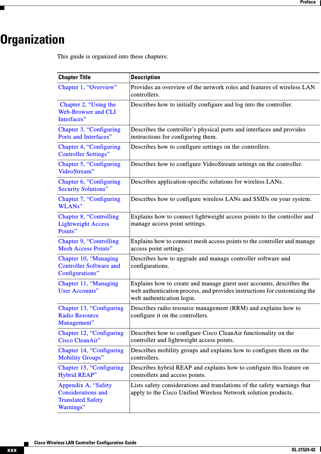
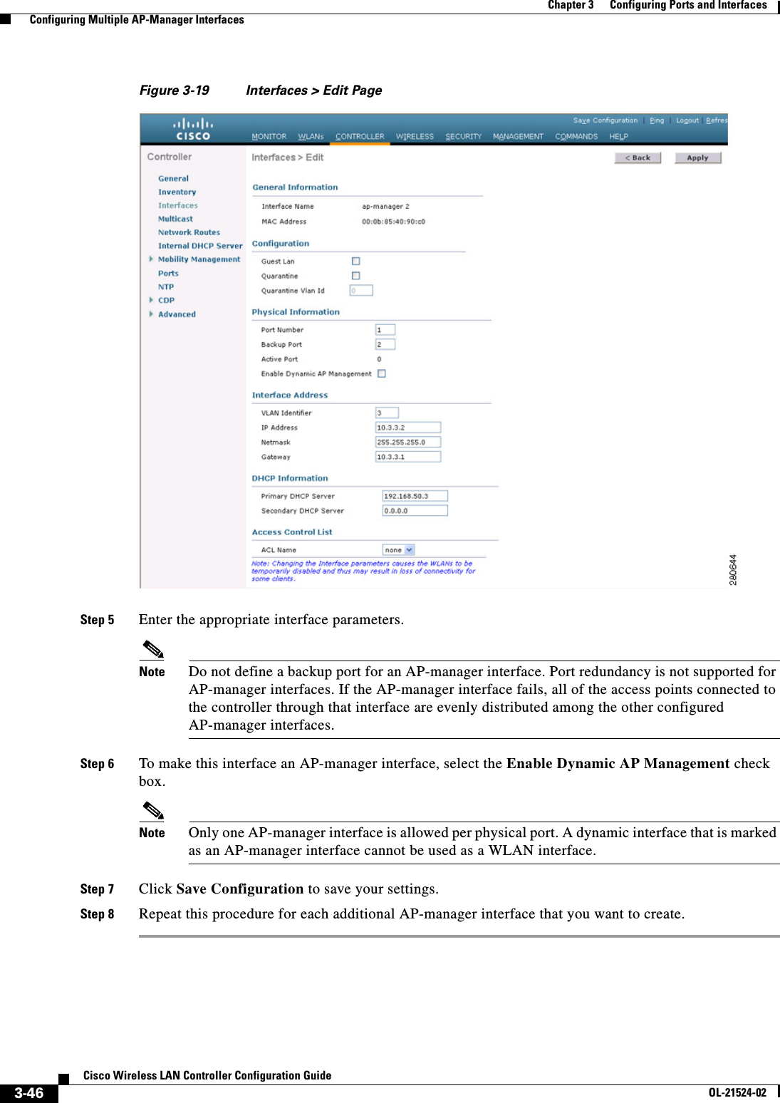
![xxxiCisco Wireless LAN Controller Configuration GuideOL-21524-02PrefaceConventionsThis document uses the following conventions: Note Means reader take note.Tip Means the following information will help you solve a problem. Appendix B, “Declarations of Conformity and Regulatory Information”Provides declarations of conformity and regulatory information for the products in the Cisco Unified Wireless Network solution.Appendix C, “End User License and Warranty”Describes the end user license and warranty that apply to the Cisco Unified Wireless Network solution products.Appendix D, “Troubleshooting”Describes the LED patterns on controllers and lightweight access points, lists system messages that can appear on the Cisco Unified Wireless Network solution interfaces, and provides CLI commands that can be used to troubleshoot problems on the controller.Appendix E, “Logical Connectivity Diagrams”Provides logical connectivity diagrams and related software commands for controllers that are integrated into other Cisco products.Chapter Title DescriptionConvention Indicationbold font Commands and keywords and user-entered text appear in bold font.italic font Document titles, new or emphasized terms, and arguments for which you supply values are in italic font.[ ] Elements in square brackets are optional.{x | y | z } Required alternative keywords are grouped in braces and separated by vertical bars.[ x | y | z ] Optional alternative keywords are grouped in brackets and separated by vertical bars.string A nonquoted set of characters. Do not use quotation marks around the string or the string will include the quotation marks.courier font Terminal sessions and information the system displays appear in courier font.< > Nonprinting characters such as passwords are in angle brackets.[ ] Default responses to system prompts are in square brackets.!, # An exclamation point (!) or a pound sign (#) at the beginning of a line of code indicates a comment line.](https://usermanual.wiki/Cisco-Systems/102075.Cisco-Wireless-LAN-Controller-Configuration-Guide-1/User-Guide-1514961-Page-33.png)
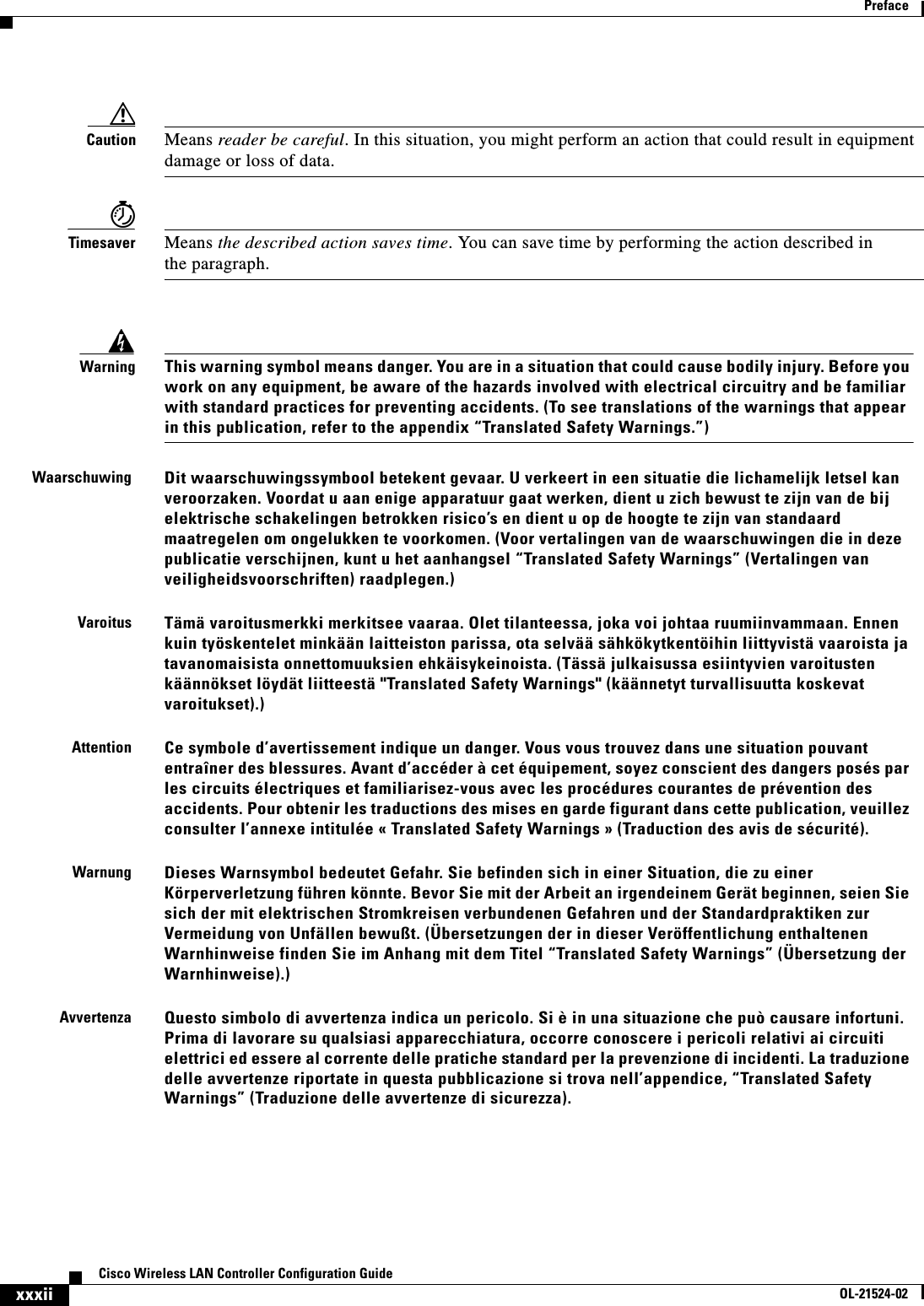
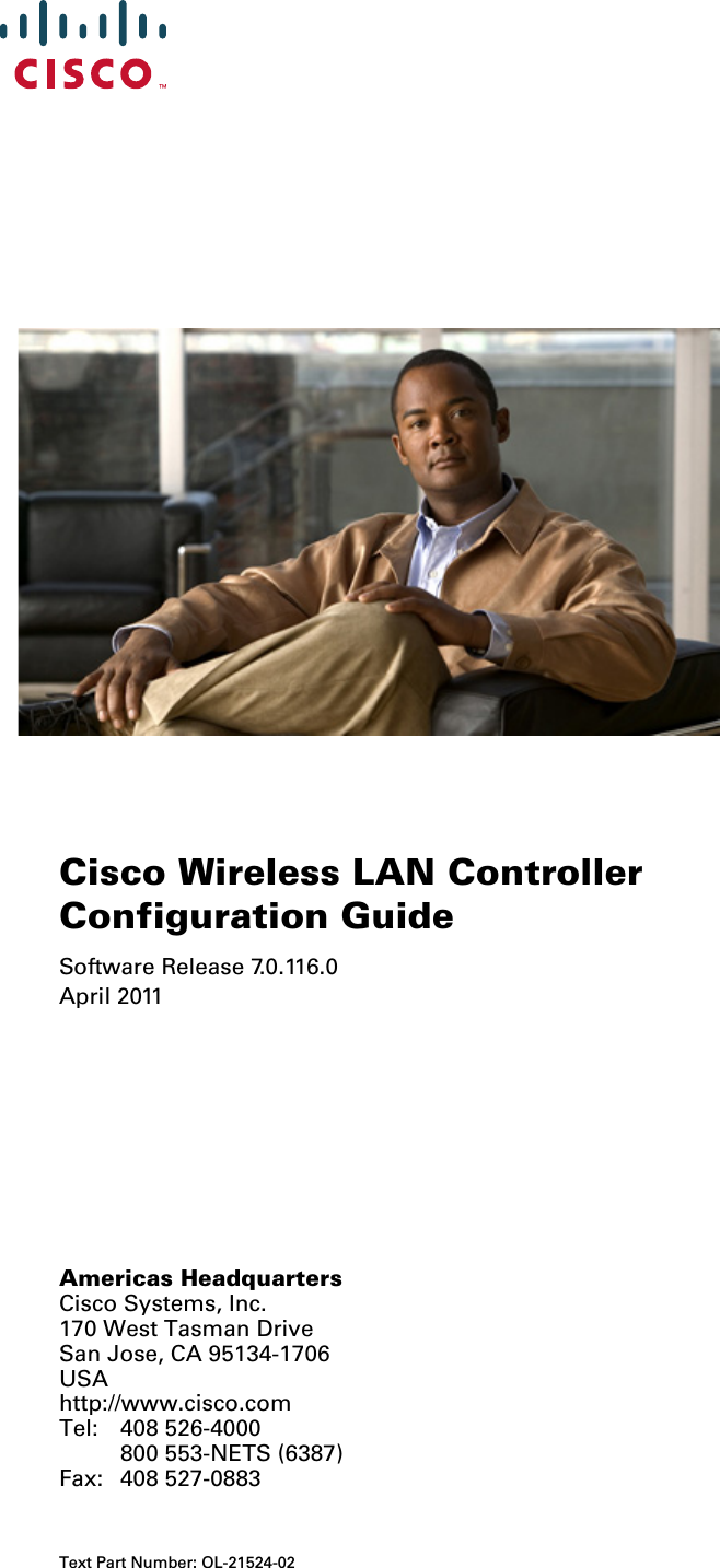
![xxxiiiCisco Wireless LAN Controller Configuration GuideOL-21524-02PrefaceRelated DocumentationThese documents provide complete information about the Cisco Unified Wireless Network solution: • Quick Start Guide: Cisco 2100 Series Wireless LAN Controllers • Quick Start Guide: Cisco 4400 Series Wireless LAN Controllers • Cisco 5500 Series Wireless Controller Installation Guide • Cisco Wireless LAN Controller Command Reference • Cisco Wireless Control System Configuration Guide • Release Noted for Cisco Wireless LAN Controllers and Lightweight Access Points, Release 7.0.116.0 • Quick Start Guide: Cisco Wireless Control System • Quick start guide and hardware installation guide for your specific lightweight access pointClick this link to browse to user documentation for the Cisco Unified Wireless Network solution:http://www.cisco.com/cisco/web/psa/default.html?mode=prodObtaining Documentation and Submitting a Service RequestFor information on obtaining documentation, submitting a service request, and gathering additional information, see monthly What’s New in Cisco Product Documentation, which also lists all new and revised Cisco technical documentation, at:http://www.cisco.com/en/US/docs/general/whatsnew/whatsnew.htmlAdvarselDette varselsymbolet betyr fare. Du befinner deg i en situasjon som kan føre til personskade. Før du utfører arbeid på utstyr, må du være oppmerksom på de faremomentene som elektriske kretser innebærer, samt gjøre deg kjent med vanlig praksis når det gjelder å unngå ulykker. (Hvis du vil se oversettelser av de advarslene som finnes i denne publikasjonen, kan du se i vedlegget "Translated Safety Warnings" [Oversatte sikkerhetsadvarsler].)AvisoEste símbolo de aviso indica perigo. Encontra-se numa situação que lhe poderá causar danos fisicos. Antes de começar a trabalhar com qualquer equipamento, familiarize-se com os perigos relacionados com circuitos eléctricos, e com quaisquer práticas comuns que possam prevenir possíveis acidentes. (Para ver as traduções dos avisos que constam desta publicação, consulte o apêndice “Translated Safety Warnings” - “Traduções dos Avisos de Segurança”).¡Advertencia!Este símbolo de aviso significa peligro. Existe riesgo para su integridad física. Antes de manipular cualquier equipo, considerar los riesgos que entraña la corriente eléctrica y familiarizarse con los procedimientos estándar de prevención de accidentes. (Para ver traducciones de las advertencias que aparecen en esta publicación, consultar el apéndice titulado “Translated Safety Warnings.”)Varning!Denna varningssymbol signalerar fara. Du befinner dig i en situation som kan leda till personskada. Innan du utför arbete på någon utrustning måste du vara medveten om farorna med elkretsar och känna till vanligt förfarande för att förebygga skador. (Se förklaringar av de varningar som förekommer i denna publikation i appendix "Translated Safety Warnings" [Översatta säkerhetsvarningar].)](https://usermanual.wiki/Cisco-Systems/102075.Cisco-Wireless-LAN-Controller-Configuration-Guide-1/User-Guide-1514961-Page-35.png)


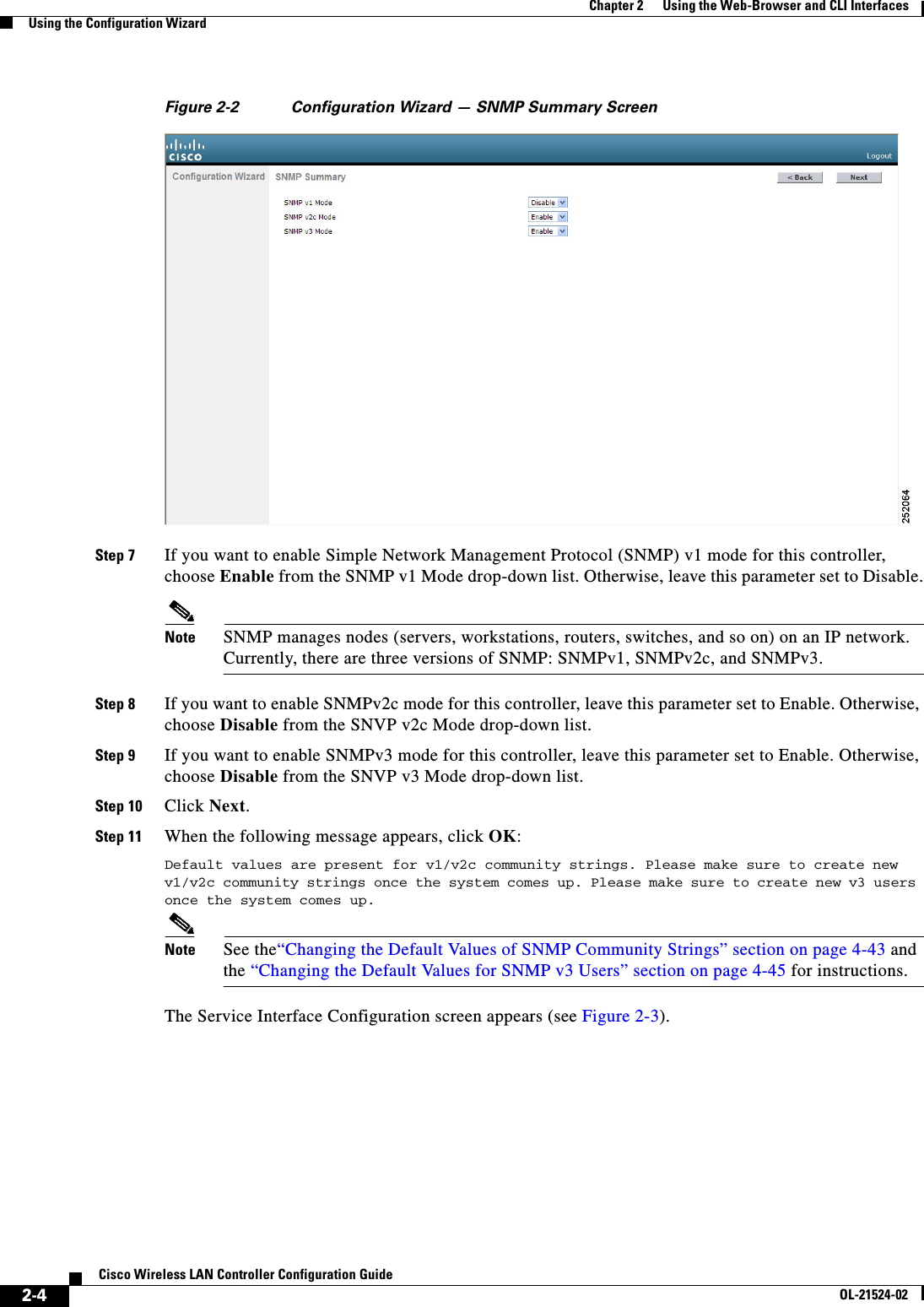
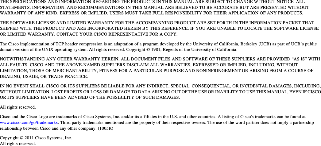
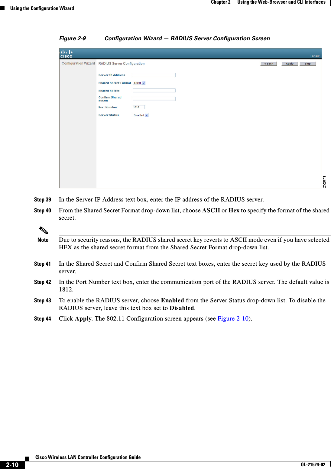
![2-9Cisco Wireless LAN Controller Configuration GuideOL-21524-02Chapter 2 Using the Web-Browser and CLI InterfacesUsing the Configuration WizardNote The virtual interface is used to support mobility management, DHCP relay, and embedded Layer 3 security such as guest web authentication and VPN termination. All controllers within a mobility group must be configured with the same virtual interface IP address.Step 33 In the DNS Host Name text box, enter the name of the Domain Name System (DNS) gateway used to verify the source of certificates when Layer 3 web authorization is enabled.Note To ensure connectivity and web authentication, the DNS server should always point to the virtual interface. If a DNS host name is configured for the virtual interface, then the same DNS host name must be configured on the DNS servers used by the client.Step 34 Click Next. The WLAN Configuration screen appears (see Figure 2-8).Figure 2-8 Configuration Wizard — WLAN Configuration ScreenStep 35 In the Profile Name text box, enter up to 32 alphanumeric characters for the profile name to be assigned to this WLAN.Step 36 In the WLAN SSID text box, enter up to 32 alphanumeric characters for the network name, or service set identifier (SSID). The SSID enables basic functionality of the controller and allows access points that have joined the controller to enable their radios.Step 37 Click Next.Step 38 When the following message appears, click OK:Default Security applied to WLAN is: [WPA2(AES)][Auth(802.1x)]. You can change this after the wizard is complete and the system is rebooted. The RADIUS Server Configuration screen appears (see Figure 2-9).](https://usermanual.wiki/Cisco-Systems/102075.Cisco-Wireless-LAN-Controller-Configuration-Guide-1/User-Guide-1514961-Page-63.png)
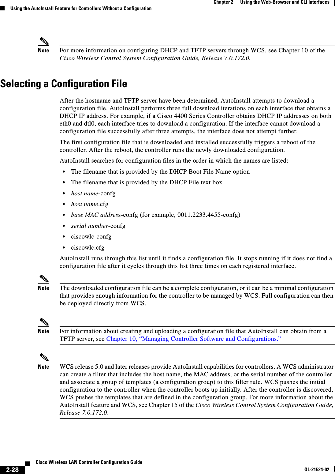
![2-26Cisco Wireless LAN Controller Configuration GuideOL-21524-02Chapter 2 Using the Web-Browser and CLI InterfacesUsing the AutoInstall Feature for Controllers Without a ConfigurationUsing the AutoInstall Feature for Controllers Without a ConfigurationWhen you boot up a controller that does not have a configuration, the AutoInstall feature can download a configuration file from a TFTP server and then load the configuration onto the controller automatically.Note The Cisco WiSM controllers do not support the AutoInstall feature.Overview of AutoInstallIf you create a configuration file on a controller that is already on the network (or through a WCS filter), place that configuration file on a TFTP server, and configure a DHCP server so that a new controller can get an IP address and TFTP server information, the AutoInstall feature can obtain the configuration file for the new controller automatically.When the controller boots, the AutoInstall process starts. The controller does not take any action until AutoInstall is notified that the configuration wizard has started. If the wizard has not started, the controller has a valid configuration.If AutoInstall is notified that the configuration wizard has started (which means that the controller does not have a configuration), AutoInstall waits for an additional 30 seconds. This time period gives you an opportunity to respond to the first prompt from the configuration wizard:Would you like to terminate autoinstall? [yes]:When the 30-second abort timeout expires, AutoInstall starts the DHCP client. You can abort the AutoInstall task even after this 30-second timeout if you enter Ye s at the prompt. However, AutoInstall cannot be aborted if the TFTP task has locked the flash and is in the process of downloading and installing a valid configuration file.Obtaining an IP Address Through DHCP and Downloading a Configuration File from a TFTP ServerAutoInstall uses the following interfaces: • Cisco 5500 and 4400 Series Controllers –eth0—Service port (untagged) –dtl0—Gigabit port 1 through the NPU (untagged) • Cisco 2100 Series Controller –dtl0—FastEthernet port 1 (untagged)AutoInstall attempts to obtain an IP address from the DHCP server until the DHCP process is successful or until you abort the AutoInstall process. The first interface to successfully obtain an IP address from the DHCP server registers with the AutoInstall task. The registration of this interface causes AutoInstall to begin the process of obtaining TFTP server information and downloading the configuration file.](https://usermanual.wiki/Cisco-Systems/102075.Cisco-Wireless-LAN-Controller-Configuration-Guide-1/User-Guide-1514961-Page-80.png)
![2-27Cisco Wireless LAN Controller Configuration GuideOL-21524-02Chapter 2 Using the Web-Browser and CLI InterfacesUsing the AutoInstall Feature for Controllers Without a ConfigurationFollowing the acquisition of the DHCP IP address for an interface, AutoInstall begins a short sequence of events to determine the host name of the controller and the IP address of the TFTP server. Each phase of this sequence gives preference to explicitly configured information over default or implied information and to explicit host names over explicit IP addresses. The process is as follows: • If at least one Domain Name System (DNS) server IP address is learned through DHCP, AutoInstall creates a /etc/resolv.conf file. This file includes the domain name and the list of DNS servers that have been received. The Domain Name Server option provides the list of DNS servers, and the Domain Name option provides the domain name. • If the domain servers are not on the same subnet as the controller, static route entries are installed for each domain server. These static routes point to the gateway that is learned through the DHCP Router option. • The host name of the controller is determined in this order by one of the following: –If the DHCP Host Name option was received, this information (truncated at the first period [.]) is used as the host name for the controller. –A reverse DNS lookup is performed on the controller IP address. If DNS returns a hostname, this name (truncated at the first period [.]) is used as the hostname for the controller. • The IP address of the TFTP server is determined in this order by one of the following: –If AutoInstall received the DHCP TFTP Server Name option, AutoInstall performs a DNS lookup on this server name. If the DNS lookup is successful, the returned IP address is used as the IP address of the TFTP server. –If the DHCP Server Host Name (sname) text box is valid, AutoInstall performs a DNS lookup on this name. If the DNS lookup is successful, the IP address that is returned is used as the IP address of the TFTP server. –If AutoInstall received the DHCP TFTP Server Address option, this address is used as the IP address of the TFTP server. –AutoInstall performs a DNS lookup on the default TFTP server name (cisco-wlc-tftp). If the DNS lookup is successful, the IP address that is received is used as the IP address of the TFTP server. –If the DHCP server IP address (siaddr) text box is nonzero, this address is used as the IP address of the TFTP server. –The limited broadcast address (255.255.255.255) is used as the IP address of the TFTP server. • If the TFTP server is not on the same subnet as the controller, a static route (/32) is installed for the IP address of the TFTP server. This static route points to the gateway that is learned through the DHCP Router option.Note For more information on configuring DHCP on a controller, See the “Configuring DHCP” section on page 7-10. Note For more information on configuring a TFTP server on a controller, see Chapter 10, “Managing Controller Software and Configurations.”](https://usermanual.wiki/Cisco-Systems/102075.Cisco-Wireless-LAN-Controller-Configuration-Guide-1/User-Guide-1514961-Page-81.png)
![2-29Cisco Wireless LAN Controller Configuration GuideOL-21524-02Chapter 2 Using the Web-Browser and CLI InterfacesManaging the System Date and TimeExample of AutoInstall OperationThe following is an example of an AutoInstall process from start to finish:Welcome to the Cisco Wizard Configuration ToolUse the '-' character to backupWould you like to terminate autoinstall? [yes]: AUTO-INSTALL: starting now...AUTO-INSTALL: interface 'service-port' - setting DHCP TFTP Filename ==> 'abcd-confg'AUTO-INSTALL: interface 'service-port' - setting DHCP TFTP Server IP ==> 1.100.108.2AUTO-INSTALL: interface 'service-port' - setting DHCP siaddr ==> 1.100.108.2AUTO-INSTALL: interface 'service-port' - setting DHCP Domain Server[0] ==> 1.100.108.2AUTO-INSTALL: interface 'service-port' - setting DHCP Domain Name ==> 'engtest.com'AUTO-INSTALL: interface 'service-port' - setting DHCP yiaddr ==> 172.19.29.253AUTO-INSTALL: interface 'service-port' - setting DHCP Netmask ==> 255.255.255.0AUTO-INSTALL: interface 'service-port' - setting DHCP Gateway ==> 172.19.29.1AUTO-INSTALL: interface 'service-port' registeredAUTO-INSTALL: interation 1 -- interface 'service-port'AUTO-INSTALL: DNS reverse lookup 172.19.29.253 ===> 'wlc-1'AUTO-INSTALL: hostname 'wlc-1'AUTO-INSTALL: TFTP server 1.100.108.2 (from DHCP Option 150)AUTO-INSTALL: attempting download of 'abcd-confg'AUTO-INSTALL: TFTP status - 'TFTP Config transfer starting.' (2)AUTO-INSTALL: interface 'management' - setting DHCP file ==> 'bootfile1'AUTO-INSTALL: interface 'management' - setting DHCP TFTP Filename ==> 'bootfile2-confg'AUTO-INSTALL: interface 'management' - setting DHCP siaddr ==> 1.100.108.2AUTO-INSTALL: interface 'management' - setting DHCP Domain Server[0] ==> 1.100.108.2AUTO-INSTALL: interface 'management' - setting DHCP Domain Server[1] ==> 1.100.108.3AUTO-INSTALL: interface 'management' - setting DHCP Domain Server[2] ==> 1.100.108.4AUTO-INSTALL: interface 'management' - setting DHCP Domain Name ==> 'engtest.com'AUTO-INSTALL: interface 'management' - setting DHCP yiaddr ==> 1.100.108.238AUTO-INSTALL: interface 'management' - setting DHCP Netmask ==> 255.255.254.0AUTO-INSTALL: interface 'management' - setting DHCP Gateway ==> 1.100.108.1AUTO-INSTALL: interface 'management' registeredAUTO-INSTALL: TFTP status - 'Config file transfer failed - Error from server: File not found' (3)AUTO-INSTALL: attempting download of 'wlc-1-confg'AUTO-INSTALL: TFTP status - 'TFTP Config transfer starting.' (2)AUTO-INSTALL: TFTP status - 'TFTP receive complete... updating configuration.' (2)AUTO-INSTALL: TFTP status - 'TFTP receive complete... storing in flash.' (2)AUTO-INSTALL: TFTP status - 'System being reset.' (2)Resetting systemManaging the System Date and TimeIf you did not configure the system date and time through the configuration wizard or if you want to change your configuration, you can follow the instructions in this section to configure the controller to obtain the date and time from a Network Time Protocol (NTP) server or to configure the date and time manually. Greenwich Mean Time (GMT) is used as the standard for setting the time zone on the controller.Note If you are configuring wIPS, you must set the controller time zone to UTC.](https://usermanual.wiki/Cisco-Systems/102075.Cisco-Wireless-LAN-Controller-Configuration-Guide-1/User-Guide-1514961-Page-83.png)

![3-15Cisco Wireless LAN Controller Configuration GuideOL-21524-02Chapter 3 Configuring Ports and Interfaces Configuring the Management, AP-Manager, Virtual, and Service-Port InterfacesNote Use the config interface quarantine vlan management vlan_id command to configure a quarantine VLAN on the management interface. • config interface vlan management {vlan-id | 0}Note Enter 0 for an untagged VLAN or a nonzero value for a tagged VLAN. We recommend using tagged VLANs for the management interface. • config interface ap-manager management {enable | disable} (for Cisco 5500 Series Controllers only)Note Use the config interface ap-manager management {enable | disable} command to enable or disable dynamic AP management for the management interface. For Cisco 5500 Series Controllers, the management interface acts like an AP-manager interface by default. If desired, you can disable the management interface as an AP-manager interface and create another dynamic interface as an AP manager. • config interface port management physical-ds-port-number (for all controllers except the 5500 series) • config interface dhcp management ip-address-of-primary-dhcp-server [ip-address-of-secondary-dhcp-server] • config interface acl management access-control-list-nameNote See Chapter 6, “Configuring Security Solutions,” for more information on ACLs.Step 4 Enter these commands if you want to be able to deploy your Cisco 5500 Series Controller behind a router or other gateway device that is using one-to-one mapping network address translation (NAT): • config interface nat-address management {enable | disable} • config interface nat-address management set public_IP_addressNAT allows a device, such as a router, to act as an agent between the Internet (public) and a local network (private). In this case, it maps the controller’s intranet IP addresses to a corresponding external address. The controller’s dynamic AP-manager interface must be configured with the external NAT IP address so that the controller can send the correct IP address in the Discovery Response.Note These NAT commands can be used only on Cisco 5500 Series Controllers and only if the management interface is configured for dynamic AP management.Note These commands are supported for use only with one-to-one-mapping NAT, where each private client has a direct and fixed mapping to a global address. These commands do not support one-to-many NAT, which uses source port mapping to enable a group of clients to be represented by a single IP address.Step 5 Enter the save config command to save your changes.](https://usermanual.wiki/Cisco-Systems/102075.Cisco-Wireless-LAN-Controller-Configuration-Guide-1/User-Guide-1514961-Page-107.png)
![3-16Cisco Wireless LAN Controller Configuration GuideOL-21524-02Chapter 3 Configuring Ports and Interfaces Configuring the Management, AP-Manager, Virtual, and Service-Port InterfacesStep 6 Enter the show interface detailed management command to verify that your changes have been saved.Step 7 If you made any changes to the management interface, enter the reset system command to reboot the controller in order for the changes to take effect.Using the CLI to Configure the AP-Manager InterfaceTo display and configure the AP-manager interface parameters using the CLI, follow these steps:Note For Cisco 5500 Series Controllers, you are not required to configure an AP-manager interface. The management interface acts like an AP-manager interface by default.Step 1 Enter the show interface summary command to view the current interfaces.Note If the system is operating in Layer 2 mode, the AP-manager interface is not listed.Step 2 Enter the show interface detailed ap-manager command to view the current AP-manager interface settings.Step 3 Enter the config wlan disable wlan-number command to disable each WLAN that uses the AP-manager interface for distribution system communication. Step 4 Enter these commands to define the AP-manager interface: • config interface address ap-manager ip-addr ip-netmask gateway • config interface vlan ap-manager {vlan-id | 0}Note Enter 0 for an untagged VLAN or a nonzero value for a tagged VLAN. We recommend using tagged VLANs for the AP-manager interface. • config interface port ap-manager physical-ds-port-number • config interface dhcp ap-manager ip-address-of-primary-dhcp-server [ip-address-of-secondary-dhcp-server] • config interface acl ap-manager access-control-list-nameNote See Chapter 6, “Configuring Security Solutions,” for more information on ACLs.Step 5 Enter the save config command to save your changes.Step 6 Enter the show interface detailed ap-manager command to verify that your changes have been saved.Using the CLI to Configure the Virtual InterfaceTo display and configure the virtual interface parameters using the CLI, follow these steps:](https://usermanual.wiki/Cisco-Systems/102075.Cisco-Wireless-LAN-Controller-Configuration-Guide-1/User-Guide-1514961-Page-108.png)
![3-17Cisco Wireless LAN Controller Configuration GuideOL-21524-02Chapter 3 Configuring Ports and Interfaces Configuring the Management, AP-Manager, Virtual, and Service-Port InterfacesStep 1 Enter the show interface detailed virtual command to view the current virtual interface settings.Step 2 Enter the config wlan disable wlan-number command to disable each WLAN that uses the virtual interface for distribution system communication. Step 3 Enter these commands to define the virtual interface: • config interface address virtual ip-addressNote For ip-address, enter any fictitious, unassigned, and unused gateway IP address. • config interface hostname virtual dns-host-nameStep 4 Enter the reset system command. At the confirmation prompt, enter Y to save your configuration changes to NVRAM. The controller reboots.Step 5 Enter the show interface detailed virtual command to verify that your changes have been saved.Using the CLI to Configure the Service-Port InterfaceTo display and configure the service-port interface parameters using the CLI, follow these steps:Step 1 Enter the show interface detailed service-port command to view the current service-port interface settings.Note The service-port interface uses the controller’s factory-set service-port MAC address.Step 2 Enter these commands to define the service-port interface: • To configure the DHCP server: config interface dhcp service-port ip-address-of-primary-dhcp- server [ip-address-of-secondary-dhcp-server] • To disable the DHCP server: config interface dhcp service-port none • To configure the IP address: config interface address service-port ip-addr ip-netmaskStep 3 The service port is used for out-of-band management of the controller. If the management workstation is in a remote subnet, you may need to add a route on the controller in order to manage the controller from that remote workstation. To do so, enter this command:config route add network-ip-addr ip-netmask gatewayStep 4 Enter the save config command to save your changes.Step 5 Enter the show interface detailed service-port command to verify that your changes have been saved.](https://usermanual.wiki/Cisco-Systems/102075.Cisco-Wireless-LAN-Controller-Configuration-Guide-1/User-Guide-1514961-Page-109.png)
![3-21Cisco Wireless LAN Controller Configuration GuideOL-21524-02Chapter 3 Configuring Ports and Interfaces Configuring Dynamic InterfacesNote When you apply a flow policer or an aggregate policer on the ingress of a Dynamic Interface VLAN for the Upstream (wireless to wired) traffic, it is not possible to police because the vLAN based policy has no effect and thus no policing occurs. When the traffic comes out of the WiSM LAG (L2) and hits the Switch Virtual Interface (SVI) (L3), the QoS policy applied is a VLAN based policy that has no effect on the policing. To enable ingress L3 VLAN based policy on the SVI, you must enable VLAN based QoS equivalent to mls qos vlan-based command on the WiSM LAG. All the previous 12.2(33)SXI releases, which support Auto LAG for WiSM only, that is 12.2(33)SXI, 12.2(33)SXI1, 12.2(33)SXI2a, 12.2(33)SXI3, and so on, do not have this WiSM CLI. Therefore, the VLAN based QoS policy applied ingress on the SVI for wireless to wired traffic never polices any traffic coming out of the WiSM LAG and hitting the SVI. The commands equivalent to the mls qos vlan-based command are as follows: Standalone: wism module module_no controller controller_no qos-vlan-based Virtual Switching System: wism switch switch_no module module_no controller controller_no qos-vlan-basedUsing the CLI to Configure Dynamic InterfacesTo configure dynamic interfaces using the CLI, follow these steps:Step 1 Enter the show interface summary command to view the current dynamic interfaces.Step 2 View the details of a specific dynamic interface by entering this command:show interface detailed operator_defined_interface_name.Step 3 Enter the config wlan disable wlan_id command to disable each WLAN that uses the dynamic interface for distribution system communication. Step 4 Enter these commands to configure dynamic interfaces: • config interface create operator_defined_interface_name {vlan_id | x} • config interface address operator_defined_interface_name ip_addr ip_netmask [gateway] • config interface vlan operator_defined_interface_name {vlan_id | 0} • config interface port operator_defined_interface_name physical_ds_port_number • config interface ap-manager operator_defined_interface_name {enable | disable}Note Use the config interface ap-manager operator_defined_interface_name {enable | disable} command to enable or disable dynamic AP management. When you enable this feature, this dynamic interface is configured as an AP-manager interface (only one AP-manager interface is allowed per physical port). A dynamic interface that is marked as an AP-manager interface cannot be used as a WLAN interface. • config interface dhcp operator_defined_interface_name ip_address_of_primary_dhcp_server [ip_address_of_secondary_dhcp_server] • config interface quarantine vlan interface_name vlan_id](https://usermanual.wiki/Cisco-Systems/102075.Cisco-Wireless-LAN-Controller-Configuration-Guide-1/User-Guide-1514961-Page-113.png)