Cisco Systems 102075 Cisco Aironet 802.11n Dual Band Access Points User Manual Cisco Wireless LAN Controller Configuration Guide 5
Cisco Systems Inc Cisco Aironet 802.11n Dual Band Access Points Cisco Wireless LAN Controller Configuration Guide 5
Contents
- 1. User manual
- 2. Cisco Wireless LAN Controller Configuration Guide_1
- 3. Cisco Wireless LAN Controller Configuration Guide_2
- 4. Cisco Wireless LAN Controller Configuration Guide_3
- 5. Cisco Wireless LAN Controller Configuration Guide_4
- 6. Cisco Wireless LAN Controller Configuration Guide_5
- 7. Cisco Wireless LAN Controller Configuration Guide_6
- 8. Cisco Wireless LAN Controller Configuration Guide_7
- 9. Cisco Wireless LAN Controller Configuration Guide_8
- 10. Cisco Wireless LAN Controller Configuration Guide_9
- 11. Cisco Wireless LAN Controller Configuration Guide_10
- 12. Cisco Wireless LAN Controller Configuration Guide_11
- 13. User Manual
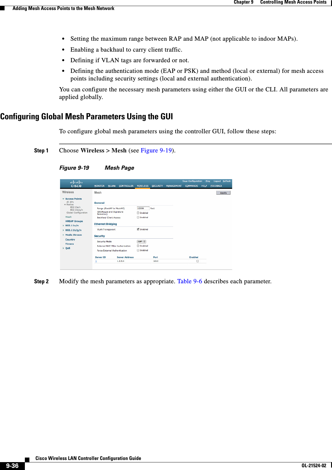
Cisco Wireless LAN Controller Configuration Guide_5
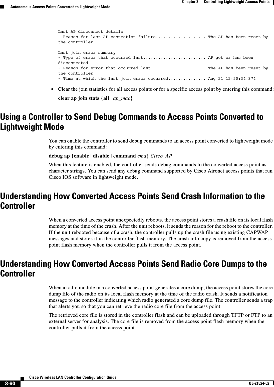
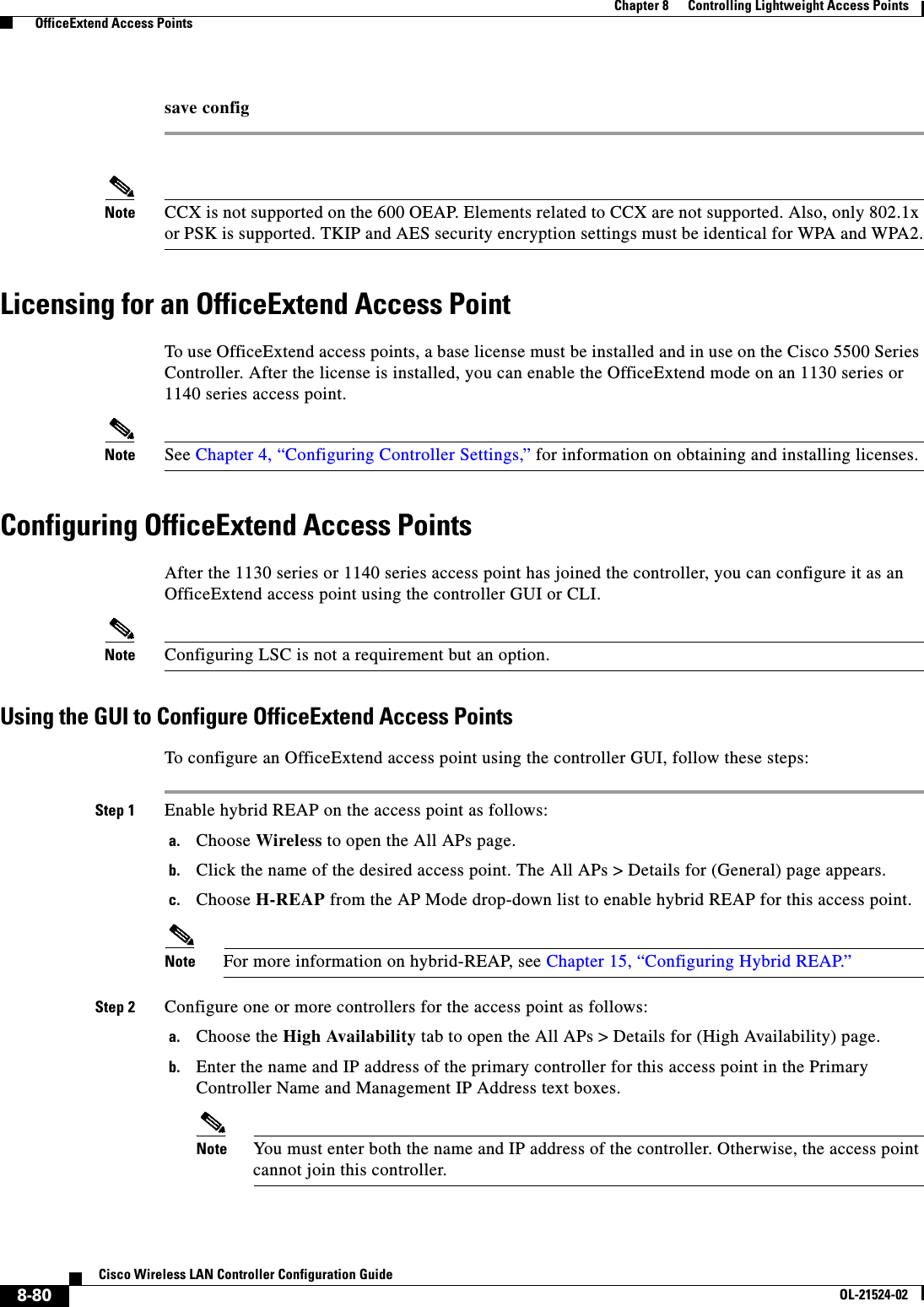
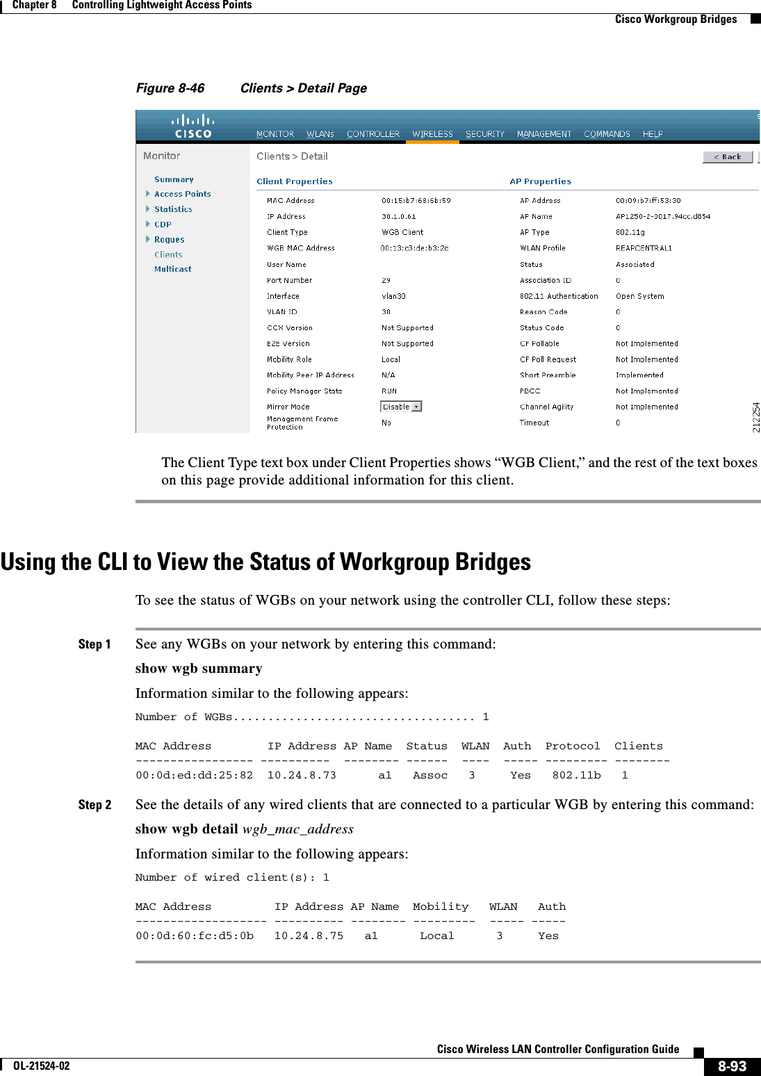
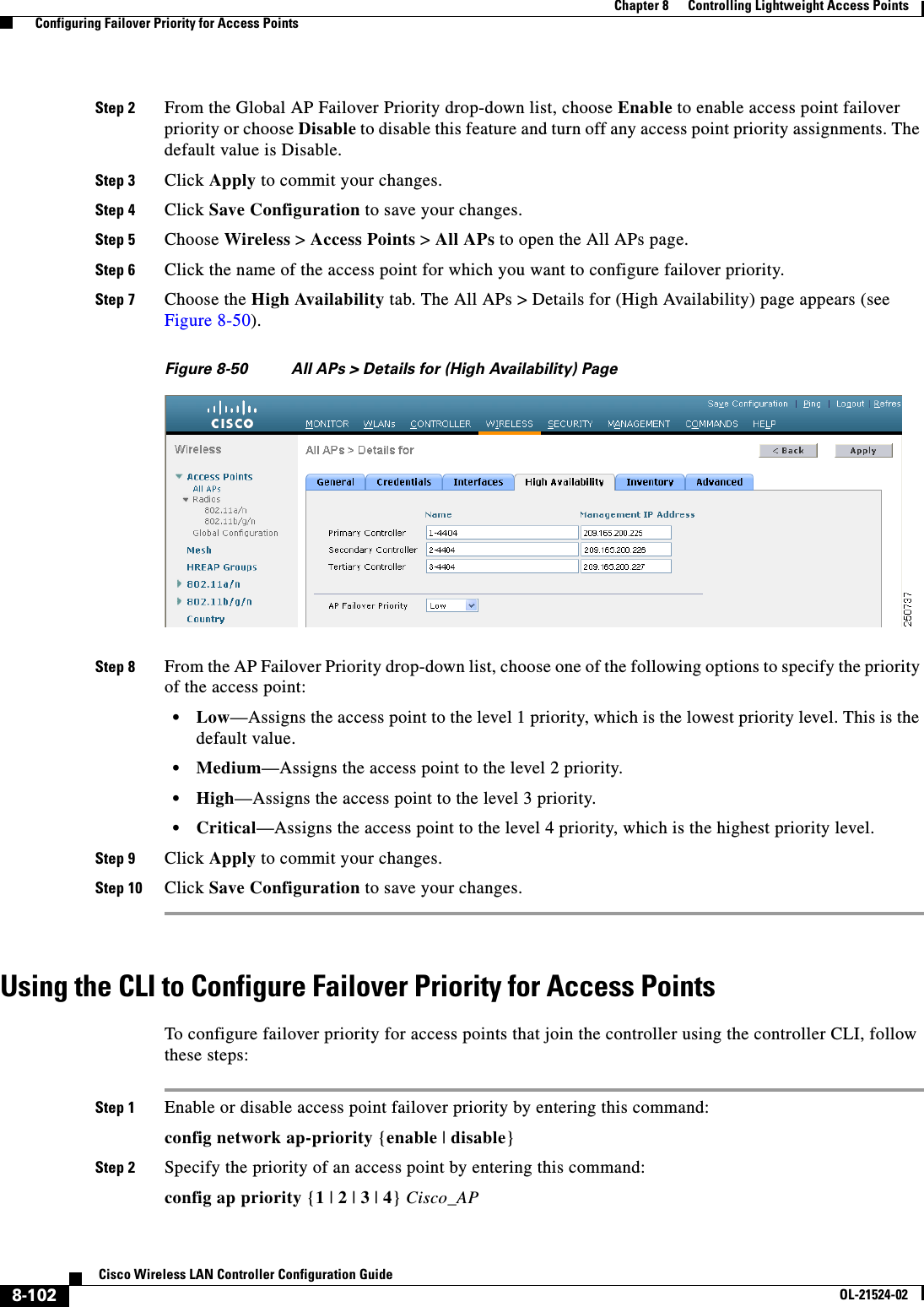
![8-91Cisco Wireless LAN Controller Configuration GuideOL-21524-02Chapter 8 Controlling Lightweight Access Points Cisco Workgroup Bridges802.11 Client Stations on Dot11Radio0:SSID [FCVTESTING] :MAC Address IP address Device Name Parent State000b.8581.6aee 10.11.12.1 WGB-client map1 - Assocap#Using the GUI to View the Status of Workgroup BridgesTo view the status of WGBs on your network using the controller GUI, follow these steps:Step 1 Choose Monitor > Clients to open the Clients page (see Figure 8-43).Figure 8-43 Clients PageThe WGB text box on the right side of the page indicates whether any of the clients on your network are workgroup bridges.Step 2 Click the MAC address of the desired client. The Clients > Detail page appears (see Figure 8-44).](https://usermanual.wiki/Cisco-Systems/102075.Cisco-Wireless-LAN-Controller-Configuration-Guide-5/User-Guide-1514965-Page-37.png)
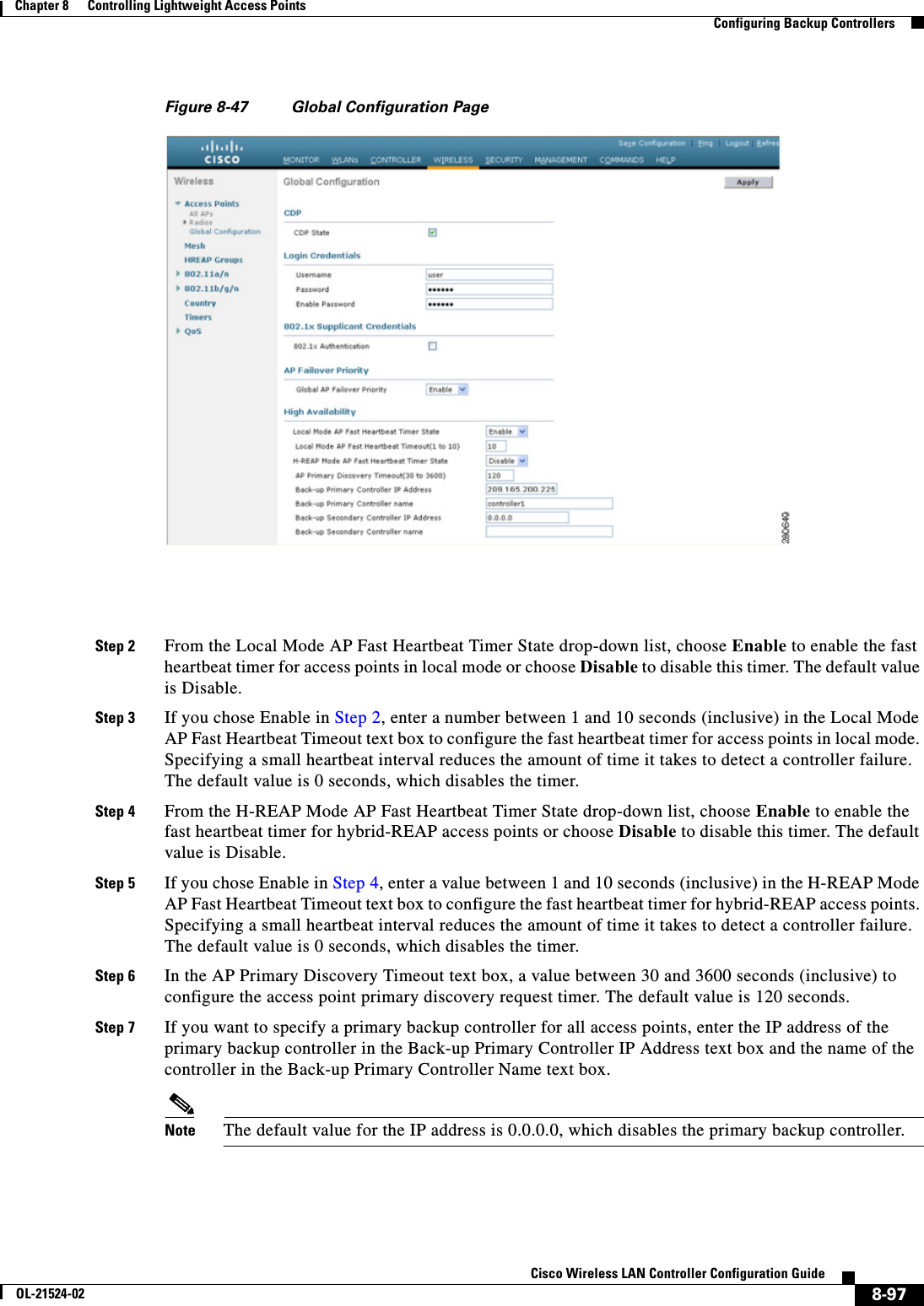
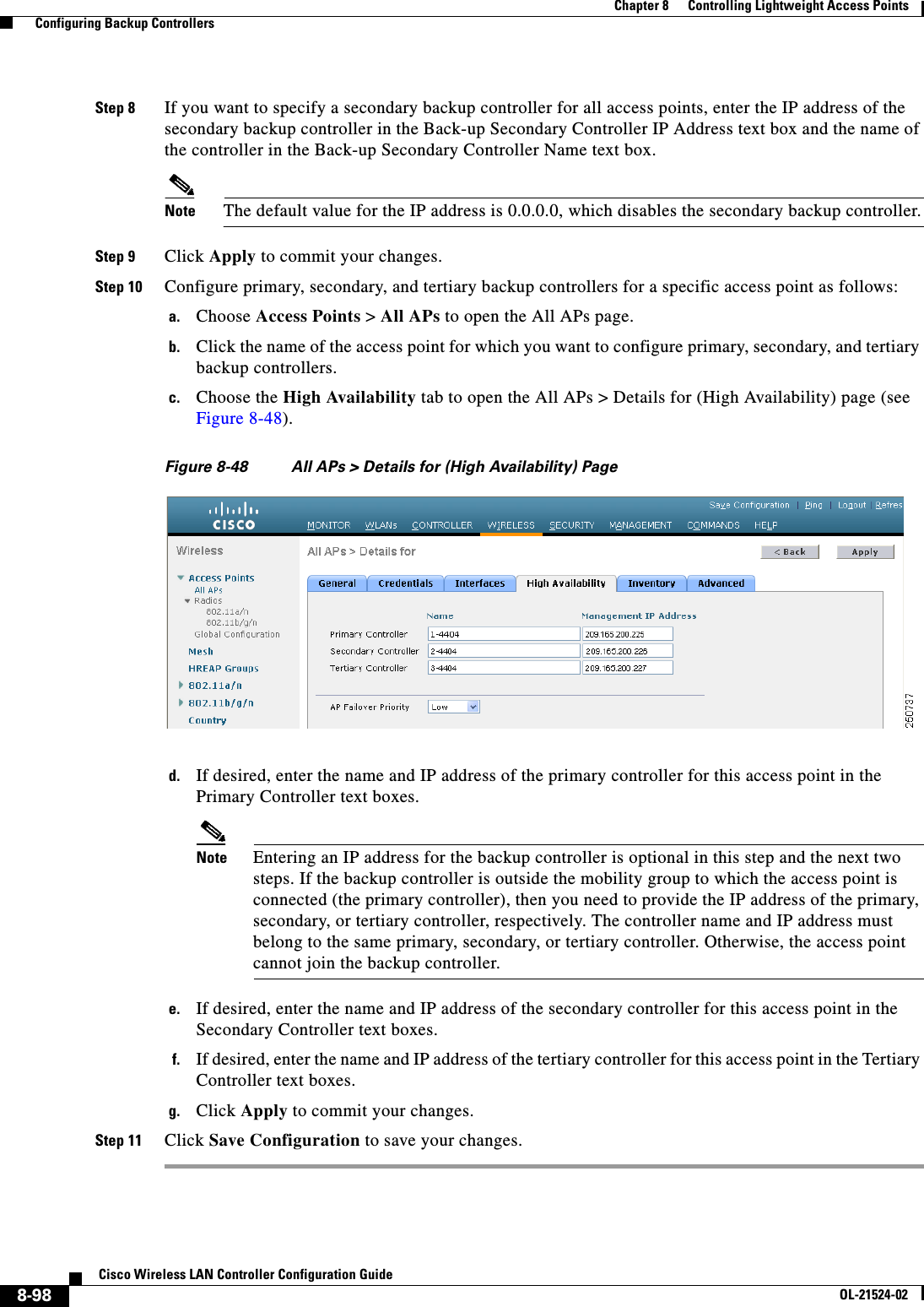
![8-99Cisco Wireless LAN Controller Configuration GuideOL-21524-02Chapter 8 Controlling Lightweight Access Points Configuring Backup ControllersUsing the CLI to Configure Backup ControllersTo configure primary, secondary, and tertiary controllers for a specific access point and to configure primary and secondary backup controllers for all access points using the controller CLI, follow these steps:Step 1 Configure a primary controller for a specific access point by entering this command:config ap primary-base controller_name Cisco_AP [controller_ip_address]Note The controller_ip_address parameter in this command and the next two commands is optional. If the backup controller is outside the mobility group to which the access point is connected (the primary controller), then you need to provide the IP address of the primary, secondary, or tertiary controller, respectively. In each command, the controller_name and controller_ip_address must belong to the same primary, secondary, or tertiary controller. Otherwise, the access point cannot join the backup controller.Step 2 Configure a secondary controller for a specific access point by entering this command:config ap secondary-base controller_name Cisco_AP [controller_ip_address]Step 3 Configure a tertiary controller for a specific access point by entering this command:config ap tertiary-base controller_name Cisco_AP [controller_ip_address]Step 4 Configure a primary backup controller for all access points by entering this command:config advanced backup-controller primary backup_controller_name backup_controller_ip_addressStep 5 Configure a secondary backup controller for all access points by entering this command:config advanced backup-controller secondary backup_controller_name backup_controller_ip_addressNote To delete a primary or secondary backup controller entry, enter 0.0.0.0 for the controller IP address.Step 6 Enable or disable the fast heartbeat timer for local or hybrid-REAP access points by entering this command:config advanced timers ap-fast-heartbeat {local | hreap | all} {enable | disable} intervalwhere all is both local and hybrid-REAP access points, and interval is a value between 1 and 10 seconds (inclusive). Specifying a small heartbeat interval reduces the amount of time that it takes to detect a controller failure. The default value is disabled.Configure the access point heartbeat timer by entering this command:config advanced timers ap-heartbeat-timeout intervalwhere interval is a value between 1 and 30 seconds (inclusive). This value should be at least three times larger than the fast heartbeat timer. The default value is 30 seconds.Caution Do not enable the fast heartbeat timer with the high latency link. If you have to enable the fast heartbeat timer, the timer value must be greater than the latency.Step 7 Configure the access point primary discovery request timer by entering this command:](https://usermanual.wiki/Cisco-Systems/102075.Cisco-Wireless-LAN-Controller-Configuration-Guide-5/User-Guide-1514965-Page-45.png)
![8-109Cisco Wireless LAN Controller Configuration GuideOL-21524-02Chapter 8 Controlling Lightweight Access Points Configuring Country CodesUsing the CLI to Configure Country CodesTo configure country codes using the controller CLI, follow these steps:Step 1 See a list of all available country codes by entering this command:show country supportedStep 2 Disable the 802.11a and 802.11b/g networks by entering these commands:config 802.11a disable networkconfig 802.11b disable networkStep 3 Configure the country codes for the countries where your access points are installed by entering this command:config country code1[,code2,code3,...]If you are entering more than one country code, separate each by a comma (for example, config country US,CA,MX). Information similar to the following appears:Changing country code could reset channel configuration.If running in RFM One-Time mode, reassign channels after this command.Check customized APs for valid channel values after this command.Are you sure you want to continue? (y/n) yStep 4 Enter Y when prompted to confirm your decision. Information similar to the following appears:Configured Country............................. Multiple Countries:US,CA,MXAuto-RF for this country combination is limited to common channels and power. KEY: * = Channel is legal in this country and may be configured manually. A = Channel is the Auto-RF default in this country. . = Channel is not legal in this country. C = Channel has been configured for use by Auto-RF. x = Channel is available to be configured for use by Auto-RF. (-) = Regulatory Domains allowed by this country.------------:+-+-+-+-+-+-+-+-+-+-+-+-+-+-802.11BG : Channels : 1 1 1 1 1 : 1 2 3 4 5 6 7 8 9 0 1 2 3 4------------:+-+-+-+-+-+-+-+-+-+-+-+-+-+- US (-AB) : A * * * * A * * * * A . . . CA (-AB) : A * * * * A * * * * A . . . MX (-NA) : A * * * * A * * * * A . . . Auto-RF : C x x x x C x x x x C . . .------------:+-+-+-+-+-+-+-+-+-+-+-+-+-+-+-+-+-+-+-+-+-+-+-+-+-+-+-+- 802.11A : 1 1 1 1 1 1 1 1 1 1 1 1 1 1 1 1Channels : 3 3 3 4 4 4 4 4 5 5 6 6 0 0 0 1 1 2 2 2 3 3 4 4 5 5 6 6--More-- or (q)uit : 4 6 8 0 2 4 6 8 2 6 0 4 0 4 8 2 6 0 4 8 2 6 0 9 3 7 1 5------------:+-+-+-+-+-+-+-+-+-+-+-+-+-+-+-+-+-+-+-+-+-+-+-+-+-+-+-+- US (-AB) : . A . A . A . A A A A A * * * * * . . . * * * A A A A * CA (-ABN) : . A . A . A . A A A A A * * * * * . . . * * * A A A A * MX (-N) : . A . A . A . A A A A A . . . . . . . . . . . A A A A * Auto-RF : . C . C . C . C C C C C . . . . . . . . . . . C C C C xStep 5 Verify your country code configuration by entering this command:show countryStep 6 See the list of available channels for the country codes configured on your controller by entering this command:show country channels](https://usermanual.wiki/Cisco-Systems/102075.Cisco-Wireless-LAN-Controller-Configuration-Guide-5/User-Guide-1514965-Page-55.png)
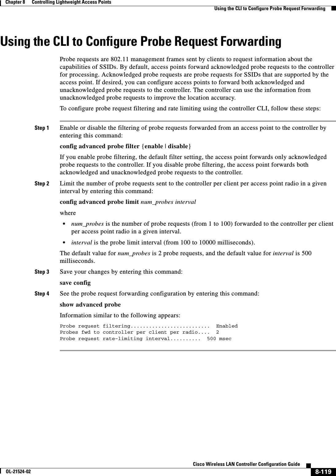
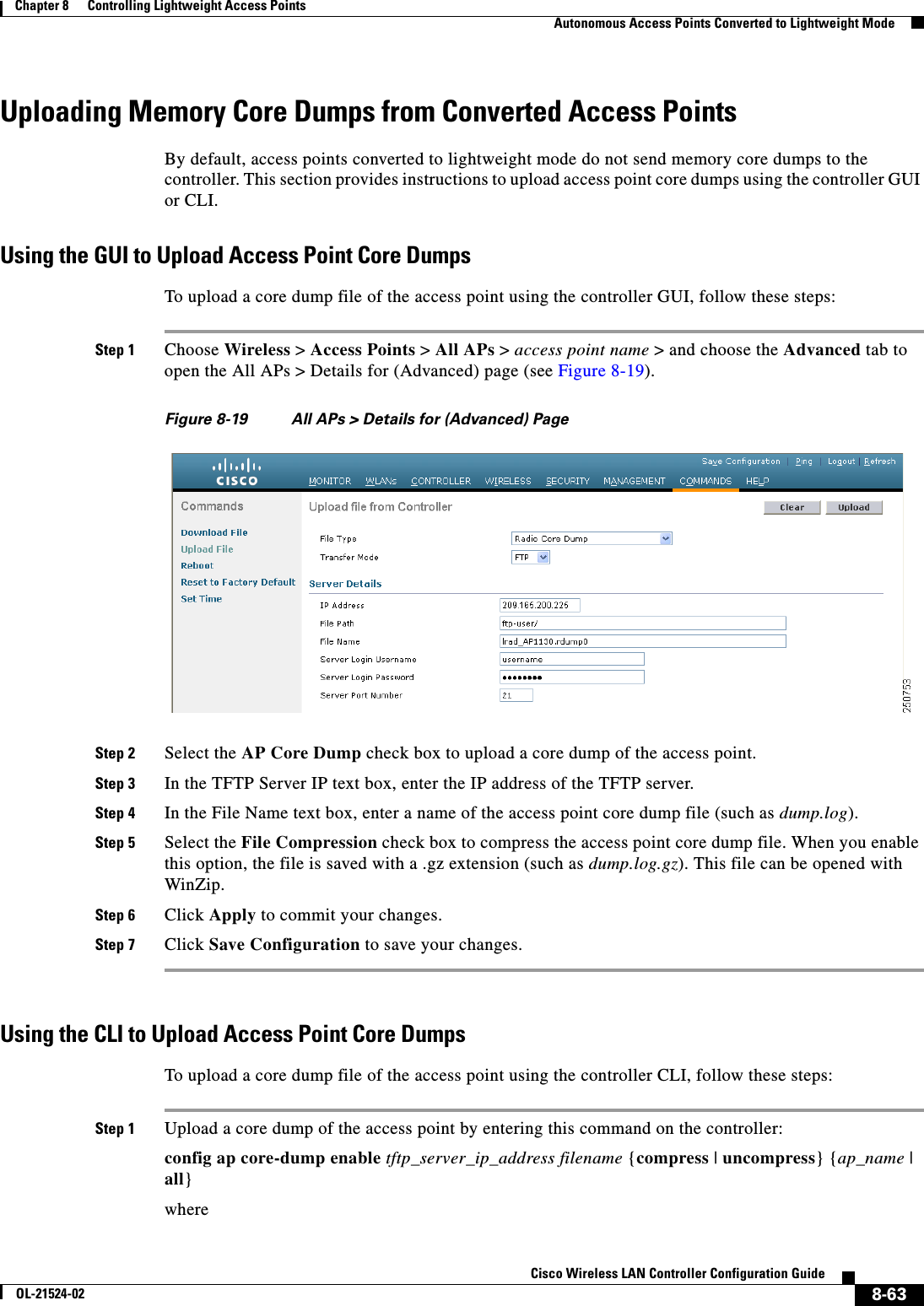
![8-121Cisco Wireless LAN Controller Configuration GuideOL-21524-02Chapter 8 Controlling Lightweight Access Points Performing a Link TestStep 4 Choose the Inventory tab to open the All APs > Details for (Inventory) page (see Figure 8-55).Figure 8-55 All APs > Details for (Inventory) PageThis page shows the inventory information for the access point.Using the CLI to Retrieve the Unique Device Identifier on Controllers and Access PointsUse these commands to retrieve the UDI on controllers and access points using the controller CLI: • show inventory—Shows the UDI string of the controller. Information similar to the following appears:NAME: "Chassis" , DESCR: "Cisco Wireless Controller"PID: WS-C3750G-24PS-W24, VID: V01, SN: FLS0952H00F • show inventory ap ap_id—Shows the UDI string of the access point specified.Performing a Link TestA link test is used to determine the quality of the radio link between two devices. Two types of link-test packets are transmitted during a link test: request and response. Any radio receiving a link-test request packet fills in the appropriate text boxes and echoes the packet back to the sender with the response type set.The radio link quality in the client-to-access point direction can differ from that in the access point-to-client direction due to the asymmetrical distribution of the transmit power and receive sensitivity on both sides. Two types of link tests can be performed: a ping test and a CCX link test.With the ping link test, the controller can test link quality only in the client-to-access point direction. The RF parameters of the ping reply packets received by the access point are polled by the controller to determine the client-to-access point link quality. With the CCX link test, the controller can also test the link quality in the access point-to-client direction. The controller issues link-test requests to the client, and the client records the RF parameters (received signal strength indicator [RSSI], signal-to-noise ratio [SNR], and so on). of the received request packet](https://usermanual.wiki/Cisco-Systems/102075.Cisco-Wireless-LAN-Controller-Configuration-Guide-5/User-Guide-1514965-Page-67.png)
![8-126Cisco Wireless LAN Controller Configuration GuideOL-21524-02Chapter 8 Controlling Lightweight Access Points Configuring Link LatencyStep 6 Click Save Configuration to save your changes.Step 7 When the All APs page reappears, click the name of the access point again.Step 8 When the All APs > Details for page reappears, choose the Advanced tab again. The link latency and data latency results appear below the Enable Link Latency check box: • Current—The current round-trip time (in milliseconds) of CAPWAP heartbeat packets or data packets from the access point to the controller and back. • Minimum—Since link latency has been enabled or reset, the minimum round-trip time (in milliseconds) of CAPWAP heartbeat packets or data packets from the access point to the controller and back. • Maximum—Since link latency has been enabled or reset, the maximum round-trip time (in milliseconds) of CAPWAP heartbeat packets or data packets from the access point to the controller and back.Step 9 To clear the current, minimum, and maximum link latency and data latency statistics on the controller for this access point, click Reset Link Latency.Step 10 After the page refreshes and the All APs > Details for page reap]pears, choose the Advanced tab. The updated statistics appear in the Minimum and Maximum text boxes.Using the CLI to Configure Link LatencyTo configure link latency using the controller CLI, follow these steps:Step 1 Enable or disable link latency for a specific access point or for all access points currently associated to the controller by entering this command:config ap link-latency {enable | disable} {Cisco_AP | all}The default value is disabled.Note The config ap link-latency {enable | disable} all command enables or disables link latency only for access points that are currently joined to the controller. It does not apply to access points that join in the future.Step 2 See the link latency results for a specific access point by entering this command:show ap config general Cisco_APInformation similar to the following appears:Cisco AP Identifier.............................. 1Cisco AP Name.................................... AP1...AP Link Latency.................................. Enabled Current Delay................................... 1 ms Maximum Delay................................... 1 ms Minimum Delay................................... 1 ms Last updated (based on AP Up Time)........... 0 days, 05 h 03 m 25 s The output of this command contains the following link latency results: • Current Delay—The current round-trip time (in milliseconds) of CAPWAP heartbeat packets from the access point to the controller and back.](https://usermanual.wiki/Cisco-Systems/102075.Cisco-Wireless-LAN-Controller-Configuration-Guide-5/User-Guide-1514965-Page-72.png)

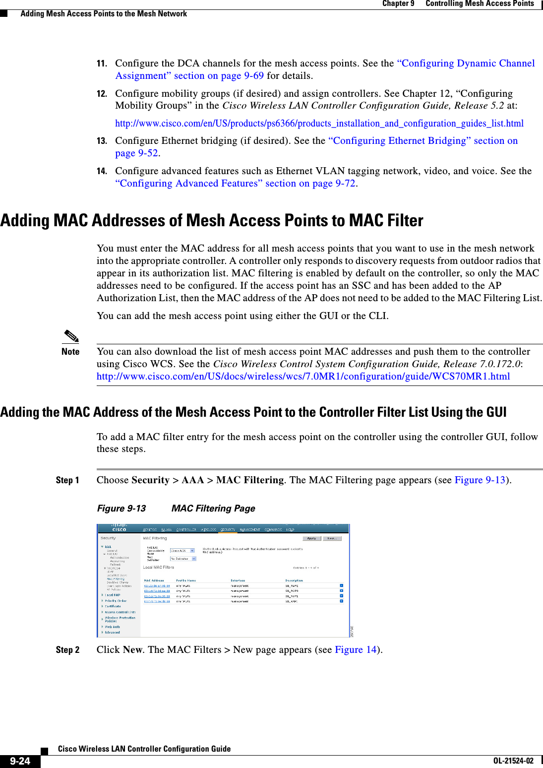
![9-25Cisco Wireless LAN Controller Configuration GuideOL-21524-02Chapter 9 Controlling Mesh Access Points Adding Mesh Access Points to the Mesh NetworkFigure 14 MAC Filters > New PageStep 3 Enter the MAC address of the mesh access point.Note For 1500 series outdoor mesh access points, specify the BVI MAC address of the mesh access point into the controller as a MAC filter. For indoor mesh access points, enter the Ethernet MAC. If the required MAC address does not appear on the exterior of the mesh access point, enter the following command at the access point console to display the BVI and Ethernet MAC addresses: sh int | i Hardware.Step 4 From the Profile Name drop-down list, select Any WLAN.Step 5 In the Description field, specify a description of the mesh access point. The text that you enter identifies the mesh access point on the controller. Note You might want to include an abbreviation of its name and the last few digits of the MAC address, such as ap1522:62:39:10. You can also note details on its location such as roof top, pole top, or its cross streets.Step 6 From the Interface Name drop-down list, choose the controller interface to which the mesh access point is to connect.Step 7 Click Apply to commit your changes. The mesh access point now appears in the list of MAC filters on the MAC Filtering page. Step 8 Click Save Configuration to save your changes.Step 9 Repeat this procedure to add the MAC addresses of additional mesh access points to the list.Adding the MAC Address of the Mesh Access Point to the Controller Filter List Using the CLITo add a MAC filter entry for the mesh access point on the controller using the controller CLI, follow these steps:Step 1 To add the MAC address of the mesh access point to the controller filter list, enter this command:config macfilter add ap_mac wlan_id interface [description]A value of zero (0) for the wlan_id parameter specifies any WLAN, and a value of zero (0) for the interface parameter specifies none. You can enter up to 32 characters for the optional description parameter.Step 2 To save your changes, enter this command:save config](https://usermanual.wiki/Cisco-Systems/102075.Cisco-Wireless-LAN-Controller-Configuration-Guide-5/User-Guide-1514965-Page-109.png)
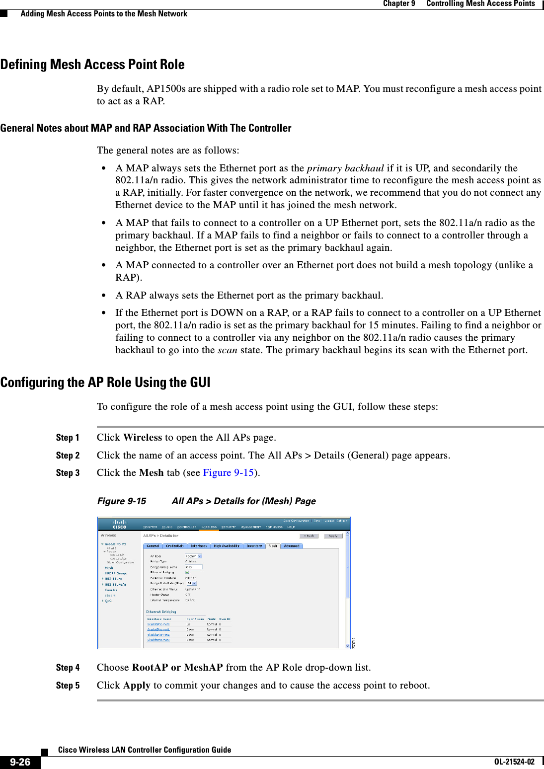
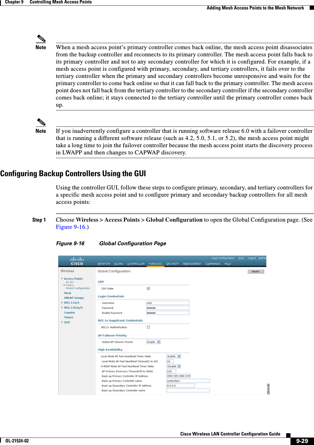
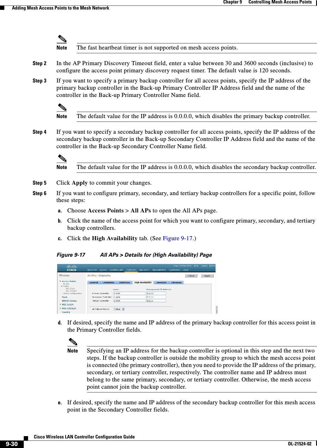
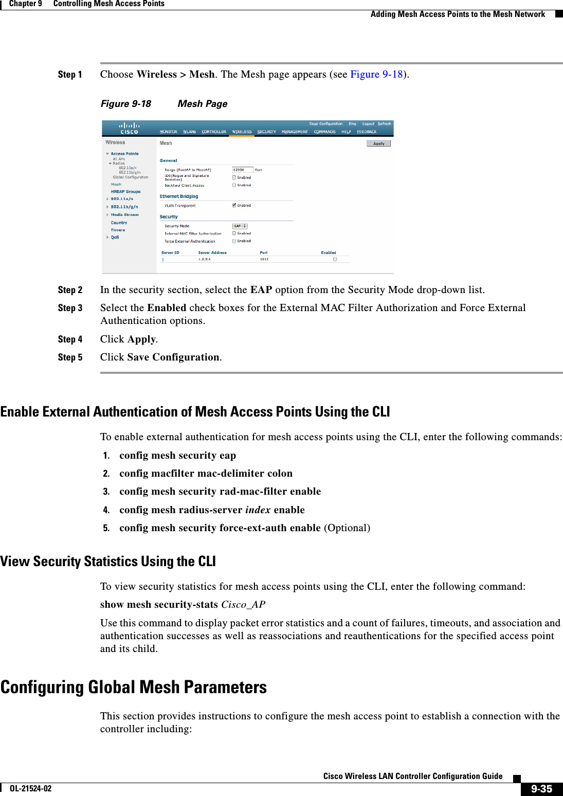
![9-31Cisco Wireless LAN Controller Configuration GuideOL-21524-02Chapter 9 Controlling Mesh Access Points Adding Mesh Access Points to the Mesh Networkf. If desired, specify the name and IP address of the tertiary backup controller for this mesh access point in the Tertiary Controller fields.g. No change is required to the AP Failover Priority value. The default value for mesh access points is critical and it cannot be modified.h. Click Apply to commit your changes.Step 7 Click Save Configuration to save your changes.Configuring Backup Controllers Using the CLIUsing the controller CLI, follow these steps to configure primary, secondary, and tertiary controllers for a specific mesh access point and to configure primary and secondary backup controllers for all mesh access points.Step 1 To configure a primary controller for a specific mesh access point, enter this command:config ap primary-base controller_name Cisco_AP [controller_ip_address]Note The controller_ip_address parameter in this command and the next two commands is optional. If the backup controller is outside the mobility group to which the mesh access point is connected (the primary controller), then you need to provide the IP address of the primary, secondary, or tertiary controller, respectively. In each command, the controller_name and controller_ip_address must belong to the same primary, secondary, or tertiary controller. Otherwise, the mesh access point cannot join the backup controller.Step 2 To configure a secondary controller for a specific mesh access point, enter this command:config ap secondary-base controller_name Cisco_AP [controller_ip_address]Step 3 To configure a tertiary controller for a specific mesh access point, enter this command:config ap tertiary-base controller_name Cisco_AP [controller_ip_address]Step 4 To configure a primary backup controller for all mesh access points, enter this command:config advanced backup-controller primary backup_controller_name backup_controller_ip_addressStep 5 To configure a secondary backup controller for all mesh access points, enter this command:config advanced backup-controller secondary backup_controller_name backup_controller_ip_addressNote To delete a primary or secondary backup controller entry, enter 0.0.0.0 for the controller IP address.Step 6 To configure the mesh access point primary discovery request timer, enter this command:config advanced timers ap-primary-discovery-timeout intervalwhere interval is a value between 30 and 3600 seconds. The default value is 120 seconds.Step 7 To configure the mesh access point discovery timer, enter this command:config advanced timers ap-discovery-timeout interval](https://usermanual.wiki/Cisco-Systems/102075.Cisco-Wireless-LAN-Controller-Configuration-Guide-5/User-Guide-1514965-Page-115.png)