Cisco Systems 102087P Cisco Aironet 802.11ac Dual Band Access Points User Manual Wireless LAN Controller Configuration Guide Part2
Cisco Systems Inc Cisco Aironet 802.11ac Dual Band Access Points Wireless LAN Controller Configuration Guide Part2
Contents
- 1. Manual
- 2. revised manual
- 3. Wireless LAN Controller Configuration Guide_Part1
- 4. Wireless LAN Controller Configuration Guide_Part2
- 5. Wireless LAN Controller Configuration Guide_Part3
- 6. Wireless LAN Controller Configuration Guide_Part4
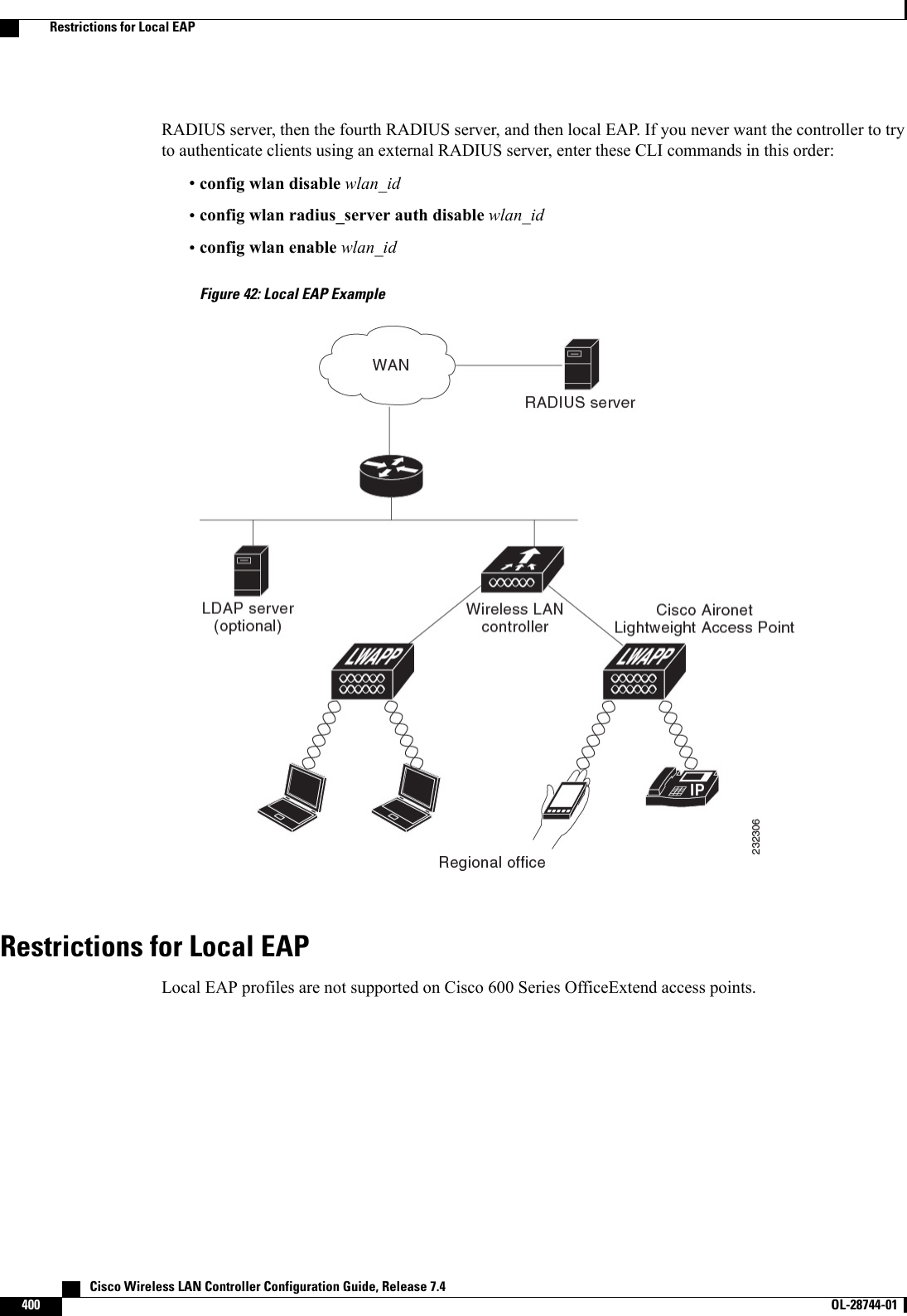
Wireless LAN Controller Configuration Guide_Part2
![Step 4 Click Save Configuration.Step 5 If you made any changes to the management or virtual interface, reboot the controller so that your changes take effect.Configuring the Management Interface (CLI)Step 1 Enter the show interface detailed management command to view the current management interface settings.The management interface uses the controller’s factory-set distribution system MAC address.NoteStep 2 Enter the config wlan disable wlan-number command to disable each WLAN that uses the management interface fordistribution system communication.Step 3 Enter these commands to define the management interface:•config interface address management ip-addr ip-netmask gateway•config interface quarantine vlan management vlan_idUse the config interface quarantine vlan management vlan_id command to configure a quarantineVLAN on the management interface.Note•config interface vlan management {vlan-id |0}Enter 0 for an untagged VLAN or a nonzero value for a tagged VLAN. We recommend using taggedVLANs for the management interface.Note•config interface ap-manager management {enable |disable} (for Cisco 5500 Series Controllers only)Use the config interface ap-manager management {enable |disable} command to enable or disabledynamic AP management for the management interface. For Cisco 5500 Series Controllers, the managementinterface acts like an AP-manager interface by default. If desired, you can disable the management interfaceas an AP-manager interface and create another dynamic interface as an AP manager.Note•config interface port management physical-ds-port-number (for all controllers except the 5500 series)•config interface dhcp management ip-address-of-primary-dhcp-server [ip-address-of-secondary-dhcp-server]•config interface acl management access-control-list-nameStep 4 Enter these commands if you want to be able to deploy your Cisco 5500 Series Controller behind a router or other gatewaydevice that is using one-to-one mapping network address translation (NAT):•config interface nat-address management {enable |disable}•config interface nat-address management set public_IP_addressNAT allows a device, such as a router, to act as an agent between the Internet (public) and a local network (private). Inthis case, it maps the controller’s intranet IP addresses to a corresponding external address. The controller’s dynamicAP-manager interface must be configured with the external NAT IP address so that the controller can send the correctIP address in the Discovery Response.Cisco Wireless LAN Controller Configuration Guide, Release 7.4 OL-28744-01 297Configuring the Management Interface (CLI)](https://usermanual.wiki/Cisco-Systems/102087P.Wireless-LAN-Controller-Configuration-Guide-Part2/User-Guide-2323188-Page-3.png)
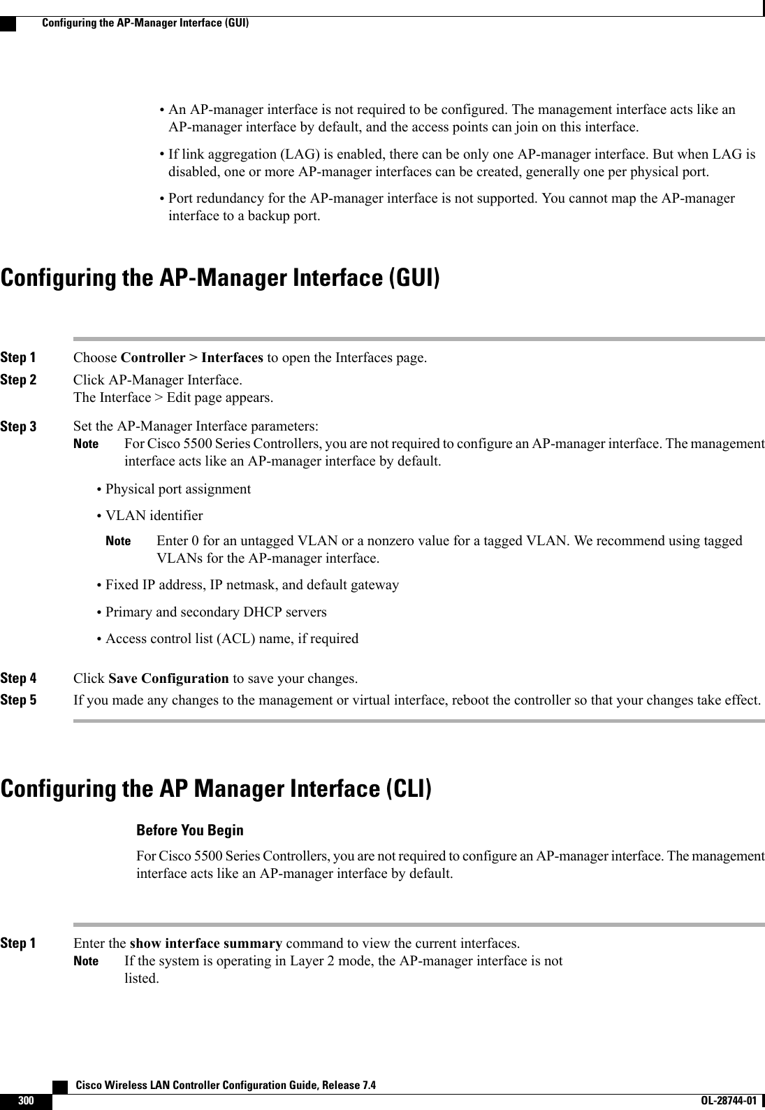
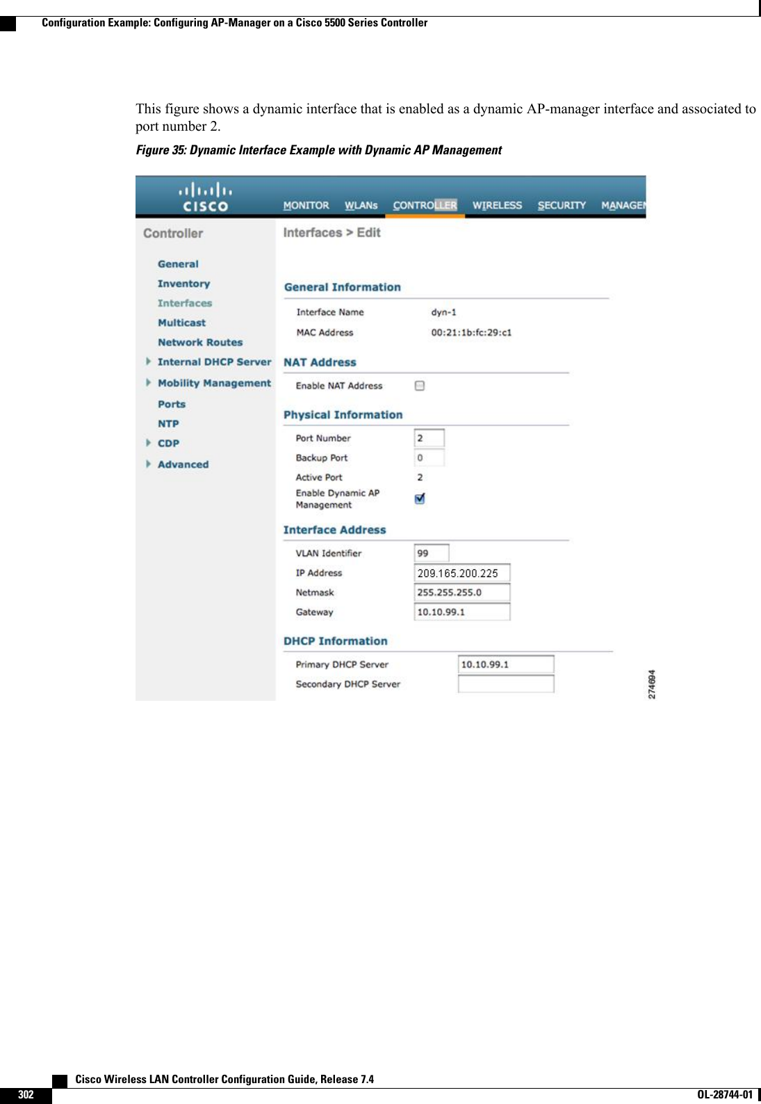
![Step 2 Enter the show interface detailed ap-manager command to view the current AP-manager interface settings.Step 3 Enter the config wlan disable wlan-number command to disable each WLAN that uses the AP-manager interface fordistribution system communication.Step 4 Enter these commands to define the AP-manager interface:•config interface address ap-manager ip-addr ip-netmask gateway•config interface vlan ap-manager {vlan-id |0}Enter 0for an untagged VLAN or a nonzero value for a tagged VLAN. We recommend using taggedVLANs for the AP-manager interface.Note•config interface port ap-manager physical-ds-port-number•config interface dhcp ap-manager ip-address-of-primary-dhcp-server [ip-address-of-secondary-dhcp-server]•config interface acl ap-manager access-control-list-nameStep 5 Enter the save config command to save your changes.Step 6 Enter the show interface detailed ap-manager command to verify that your changes have been saved.Configuration Example: Configuring AP-Manager on a Cisco 5500 SeriesControllerFor a Cisco 5500 Series Controller, we recommend that you have eight dynamic AP-manager interfaces andassociate them to the eight Gigabit ports of the controller when LAG is not used. If you are using themanagement interface, which acts like an AP-manager interface by default, you must create only seven moredynamic AP-manager interfaces and associate them to the remaining seven Gigabit ports.Cisco Wireless LAN Controller Configuration Guide, Release 7.4 OL-28744-01 301Configuration Example: Configuring AP-Manager on a Cisco 5500 Series Controller](https://usermanual.wiki/Cisco-Systems/102087P.Wireless-LAN-Controller-Configuration-Guide-Part2/User-Guide-2323188-Page-7.png)

![Configuring Dynamic Interfaces (CLI)Step 1 Enter the show interface summary command to view the current dynamic interfaces.Step 2 View the details of a specific dynamic interface by entering this command:show interface detailed operator_defined_interface_name.Interface names that contain spaces must be enclosed in double quotes. For example: config interface create"vlan 25"NoteStep 3 Enter the config wlan disable wlan_id command to disable each WLAN that uses the dynamic interface for distributionsystem communication.Step 4 Enter these commands to configure dynamic interfaces:•config interface create operator_defined_interface_name {vlan_id |x}•config interface address interface ip_addr ip_netmask [gateway]•config interface vlan operator_defined_interface_name {vlan_id |o}•config interface port operator_defined_interface_name physical_ds_port_number•config interface ap-manager operator_defined_interface_name {enable |disable}Use the config interface ap-manager operator_defined_interface_name {enable |disable} commandto enable or disable dynamic AP management. When you enable this feature, this dynamic interface isconfigured as an AP-manager interface (only one AP-manager interface is allowed per physical port). Adynamic interface that is marked as an AP-manager interface cannot be used as a WLAN interface.Note•config interface dhcp operator_defined_interface_name ip_address_of_primary_dhcp_server[ip_address_of_secondary_dhcp_server]•config interface quarantine vlan interface_name vlan_idUse the config interface quarantine vlan interface_name vlan_id command to configure a quarantineVLAN on any interface.Note•config interface acl operator_defined_interface_name access_control_list_nameStep 5 Enter these commands if you want to be able to deploy your Cisco 5500 Series Controller behind a router or other gatewaydevice that is using one-to-one mapping network address translation (NAT):•config interface nat-address dynamic-interface operator_defined_interface_name {enable |disable}•config interface nat-address dynamic-interface operator_defined_interface_name set public_IP_addressNAT allows a device, such as a router, to act as an agent between the Internet (public) and a local network (private). Inthis case, it maps the controller’s intranet IP addresses to a corresponding external address. The controller’s dynamicAP-manager interface must be configured with the external NAT IP address so that the controller can send the correctIP address in the Discovery Response.These commands are supported for use only with one-to-one-mapping NAT, whereby each private client has adirect and fixed mapping to a global address. These commands do not support one-to-many NAT, which usessource port mapping to enable a group of clients to be represented by a single IP address.Note Cisco Wireless LAN Controller Configuration Guide, Release 7.4312 OL-28744-01 Configuring Dynamic Interfaces (CLI)](https://usermanual.wiki/Cisco-Systems/102087P.Wireless-LAN-Controller-Configuration-Guide-Part2/User-Guide-2323188-Page-18.png)

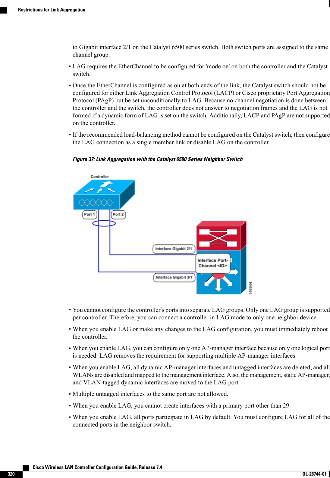
![•AP-manager interfaces do not need to be on the same VLAN or IP subnet, and they may or may not beon the same VLAN or IP subnet as the management interface. However, we recommend that you configureall AP-manager interfaces on the same VLAN or IP subnet.•If the port of one of the AP-manager interfaces fails, the controller clears the state of the access points,and the access points must reboot to reestablish communication with the controller using the normalcontroller join process. The controller no longer includes the failed AP-manager interface in the CAPWAPor LWAPP discovery responses. The access points then rejoin the controller and are load balanced amongthe available AP-manager interfaces.Creating Multiple AP-Manager Interfaces (GUI)Step 1 Choose Controller > Interfaces to open the Interfaces page.Step 2 Click New.The Interfaces > New page appears.Step 3 Enter an AP-manager interface name and a VLAN identifier.Step 4 Click Apply to commit your changes. The Interfaces > Edit page appears.Step 5 Enter the appropriate interface parameters.Every interface supports primary and backup port with the following exceptionsNote•Dynamic interface is converted to AP manager which does not support backup of port configuration.•If AP manager is enabled on management interface and when management interface moves to backup portbecause of primary port failure, the AP manager will be disabled.Step 6 To make this interface an AP-manager interface, select the Enable Dynamic AP Management check box.Only one AP-manager interface is allowed per physical port. A dynamic interface that is marked as an AP-managerinterface cannot be used as a WLAN interface.NoteStep 7 Click Save Configuration to save your settings.Step 8 Repeat this procedure for each additional AP-manager interface that you want to create.Creating Multiple AP-Manager Interfaces (CLI)Step 1 Enter these commands to create a new interface:•config interface create operator_defined_interface_name {vlan_id |x}•config interface address operator_defined_interface_name ip_addr ip_netmask [gateway]•config interface vlan operator_defined_interface_name {vlan_id |o}•config interface port operator_defined_interface_name physical_ds_port_number Cisco Wireless LAN Controller Configuration Guide, Release 7.4324 OL-28744-01 Creating Multiple AP-Manager Interfaces (GUI)](https://usermanual.wiki/Cisco-Systems/102087P.Wireless-LAN-Controller-Configuration-Guide-Part2/User-Guide-2323188-Page-30.png)
![•config interface dhcp operator_defined_interface_name ip_address_of_primary_dhcp_server[ip_address_of_secondary_dhcp_server]•config interface quarantine vlan interface_name vlan_idUse this command to configure a quarantine VLAN on anyinterface.Note•config interface acl operator_defined_interface_name access_control_list_nameStep 2 To make this interface an AP-manager interface, enter this command:{config interface ap-manager operator_defined_interface_name enable | disable}Only one AP-manager interface is allowed per physical port. A dynamic interface that is marked as an AP-managerinterface cannot be used as a WLAN interface.NoteStep 3 Enter save config command to save your changes.Step 4 Repeat this procedure for each additional AP-manager interface that you want to create.Cisco Wireless LAN Controller Configuration Guide, Release 7.4 OL-28744-01 325Creating Multiple AP-Manager Interfaces (CLI)](https://usermanual.wiki/Cisco-Systems/102087P.Wireless-LAN-Controller-Configuration-Guide-Part2/User-Guide-2323188-Page-31.png)


![a) Choose Monitor > Clients. The Clients page appears.b) Check if the 802.11a/n or 802.11b/g/n network clients have the associated access points.c) Choose Monitor > Multicast. The Multicast Groups page appears.d) Select the MGID check box for the VideoStream to the clients.e) Click MGID. The Multicast Group Detail page appears. Check the Multicast Status details.Configuring VideoStream (CLI)Step 1 Configure the multicast-direct feature on WLANs media stream by entering this command:config wlan media-stream multicast-direct {wlan_id |all} {enable |disable}Step 2 Enable or disable the multicast feature by entering this command:config media-stream multicast-direct {enable |disable}Step 3 Configure various message configuration parameters by entering this command:config media-stream message {state [enable |disable] | url url |email email |phone phone _number |note note}Step 4 Save your changes by entering this command:save configStep 5 Configure various global media-stream configurations by entering this command:config media-stream add multicast-direct stream-name media_stream_name start_IP end_IP [template {very-coarse|coarse |ordinary |low-resolution |med-resolution |high-resolution} | detail {Max_bandwidth bandwidth |packetsize packet_size |Re-evaluation re-evaluation {periodic |initial}} video video priority {drop |fallback}•The Resource Reservation Control (RRC) parameters are assigned with the predefined values based on the valuesassigned to the template.•The following templates are used to assign RRC parameters to the media stream:◦Very Coarse (below 3000 kbps)◦Coarse (below 500 kbps)◦Ordinary (below 750 kbps)◦Low Resolution (below 1 mbps)◦Medium Resolution (below 3 mbps)◦High Resolution (below 5 mbps)Step 6 Delete a media stream by entering this command:config media-stream delete media_stream_nameStep 7 Enable a specific enhanced distributed channel access (EDC) profile by entering this command:config advanced{801.11a |802.11b}edca-parameters optimized-video-voiceCisco Wireless LAN Controller Configuration Guide, Release 7.4 OL-28744-01 343Configuring VideoStream (CLI)](https://usermanual.wiki/Cisco-Systems/102087P.Wireless-LAN-Controller-Configuration-Guide-Part2/User-Guide-2323188-Page-49.png)
![Step 8 Enable the admission control on the desired bandwidth by entering the following commands:•Enable bandwidth-based voice CAC for 802.11a or 802.11b/g network by entering this command:config {802.11a |802.11b}cac voice acm enable•Set the percentage of the maximum bandwidth allocated to clients for voice applications on the 802.11a or 802.11b/gnetwork by entering this command:config {802.11a |802.11b}cac voice max-bandwidth bandwidth•Configure the percentage of the maximum allocated bandwidth reserved for roaming voice clients on the 802.11aor 802.11b/g network by entering this command:config {802.11a |802.11b}cac voice roam-bandwidth bandwidthFor TSpec and SIP based CAC for video calls, only Static method is supported.NoteStep 9 Set the maximum number of streams per radio and/or per client by entering these commands:•Set the maximum limit to the number multicast streams per radio by entering this command:config {802.11a |802.11b}media-stream multicast-direct radio-maximum [value |no-limit]•Set the maximum number of multicast streams per client by entering this command:config {802.11a |802.11b}media-stream multicast-direct client-maximum [value |no-limit]Step 10 Save your changes by entering this command:save configViewing and Debugging Media Streams•See the configured media streams by entering this command:show wlan wlan_id•See the details of the media stream name by entering this command:show 802.11{a | b | h} media-stream media-stream_name•See the clients for a media stream by entering this command:show 802.11a media-stream client media-stream-name•See a summary of the media stream and client information by entering this command:show media-stream group summary•See details about a particular media stream group by entering this command:show media-stream group detail media_stream_name•See details of the 802.11a or 802.11b media resource reservation configuration by entering this command:show {802.11a | 802.11b} media-stream rrc•Enable debugging of the media stream history by entering this command: Cisco Wireless LAN Controller Configuration Guide, Release 7.4344 OL-28744-01 Viewing and Debugging Media Streams](https://usermanual.wiki/Cisco-Systems/102087P.Wireless-LAN-Controller-Configuration-Guide-Part2/User-Guide-2323188-Page-50.png)


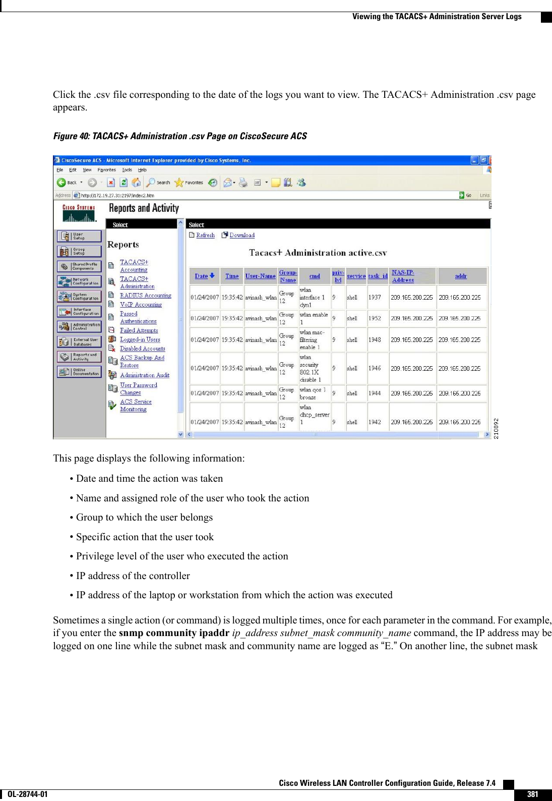
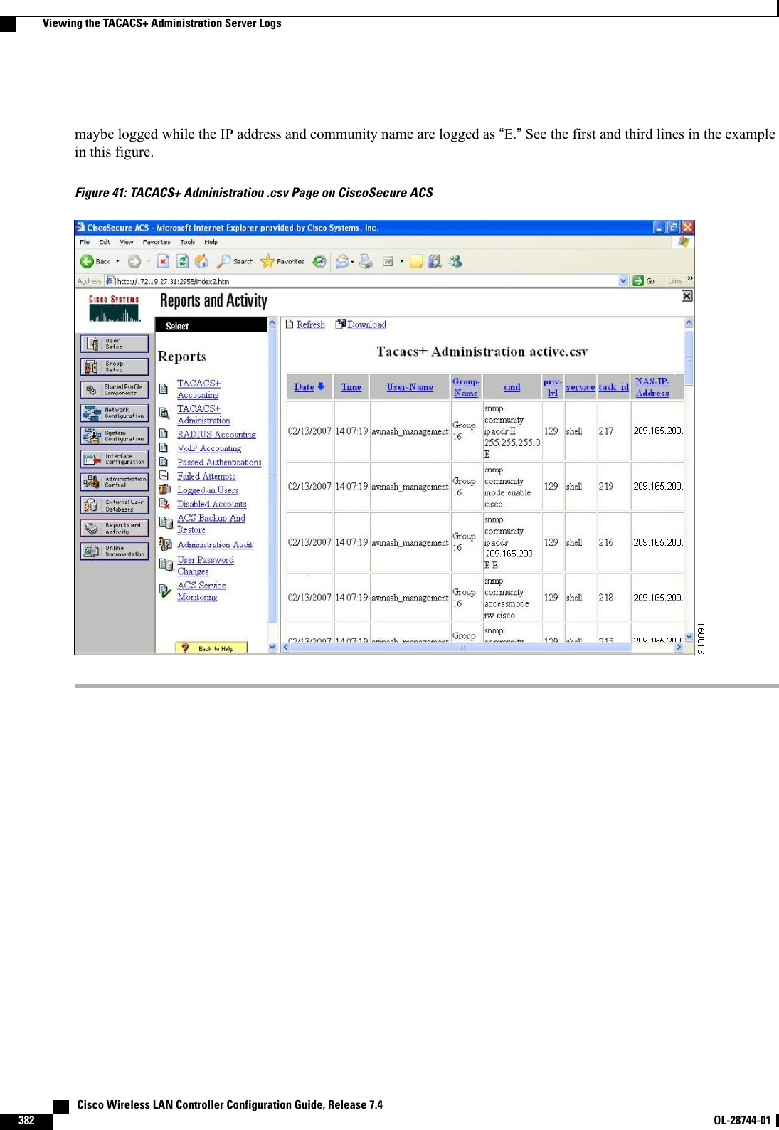
![◦config tacacs athr (enable |disable}index—Enables or disables a TACACS+ authorizationserver.◦config tacacs athr server-timeout index timeout—Configures the retransmission timeout valuefor a TACACS+ authorization server.•Configure a TACACS+ accounting server by entering these commands:◦config tacacs acct add index server_ip_address port# {ascii |hex}shared_secret—Adds aTACACS+ accounting server.◦config tacacs acct delete index—Deletes a previously added TACACS+ accounting server.◦config tacacs acct (enable |disable}index—Enables or disables a TACACS+ accounting server.◦config tacacs acct server-timeout index timeout—Configures the retransmission timeout valuefor a TACACS+ accounting server.•See TACACS+ statistics by entering these commands:◦show tacacs summary—Shows a summary of TACACS+ servers and statistics.◦show tacacs auth stats—Shows the TACACS+ authentication server statistics.◦show tacacs athr stats—Shows the TACACS+ authorization server statistics.◦show tacacs acct stats—Shows the TACACS+ accounting server statistics.•Clear the statistics for one or more TACACS+ servers by entering this command:clear stats tacacs [auth |athr |acct] {index |all}•Configure the order of authentication when multiple databases are configured by entering this command.The default setting is local and then radius.config aaa auth mgmt [radius |tacacs]See the current management authentication server order by entering the show aaa auth command.•Make sure the controller can reach the TACACS+ server by entering this command:ping server_ip_address•Enable or disable TACACS+ debugging by entering this command:debug aaa tacacs {enable |disable}•Save your changes by entering this command:save configViewing the TACACS+ Administration Server LogsStep 1 On the ACS main page, in the left navigation pane, choose Reports and Activity.Step 2 Under Reports, choose TACACS+ Administration. Cisco Wireless LAN Controller Configuration Guide, Release 7.4380 OL-28744-01 Viewing the TACACS+ Administration Server Logs](https://usermanual.wiki/Cisco-Systems/102087P.Wireless-LAN-Controller-Configuration-Guide-Part2/User-Guide-2323188-Page-86.png)


![Applying a Preauthentication Access Control List to a WLANStep 1 Choose WLANs to open the WLANs page.Step 2 Click the ID number of the desired WLAN to open the WLANs > Edit page.Step 3 Choose the Security and Layer 3 tabs to open the WLANs > Edit (Security > Layer 3) page.Step 4 Select the Web Policy check box.Step 5 From the Preauthentication ACL drop-down list, choose the desired ACL and click Apply. None is the default value.Step 6 Click Save Configuration to save your changes.Configuring and Applying Access Control Lists (CLI)Configuring Access Control ListsStep 1 See all of the ACLs that are configured on the controller by entering this command:show [ipv6]acl summaryStep 2 See detailed information for a particular ACL by entering this command:show [ipv6]acl detailed acl_nameThe Counter text box increments each time a packet matches an ACL rule, and the DenyCounter text box incrementseach time a packet does not match any of the rules.If a traffic/request is allowed from the controller by a permit rule, then the response to the traffic/request in theopposite direction also is allowed and cannot be blocked by a deny rule in the ACL.NoteStep 3 Enable or disable ACL counters for your controller by entering this command:config acl counter {start |stop}If you want to clear the current counters for an ACL, enter the clear acl counters acl_name command.NoteStep 4 Add a new ACL by entering this command:config [ipv6] acl create acl_name.You can enter up to 32 alphanumeric characters for the acl_name parameter.When you try to create an interface name with space, the controller CLI does not create an interface. For example,if you want to create an interface name int 3, the CLI will not create this since there is a space between int and3. If you want to use int 3 as the interface name, you need to enclose within single quotes like ‘int 3’.NoteStep 5 Add a rule for an ACL by entering this command:config [ipv6] acl rule add acl_name rule_indexStep 6 Configure an ACL rule by entering config [ipv6] acl rule command:Step 7 Save your settings by entering this command:save config Cisco Wireless LAN Controller Configuration Guide, Release 7.4430 OL-28744-01 Configuring and Applying Access Control Lists (CLI)](https://usermanual.wiki/Cisco-Systems/102087P.Wireless-LAN-Controller-Configuration-Guide-Part2/User-Guide-2323188-Page-136.png)
![To delete an ACL, enter the config [ipv6]acl delete acl_name command. To delete an ACL rule, enter theconfig [ipv6]acl rule delete acl_name rule_index command.NoteApplying Access Control ListsStep 1 Perform any of the following:•To apply an ACL to the data path, enter this command:config acl apply acl_name•To apply an ACL to the controller CPU to restrict the type of traffic (wired, wireless, or both) reaching the CPU,enter this command:config acl cpu acl_name {wired | wireless | both}To see the ACL that is applied to the controller CPU, enter the show acl cpu command. To remove theACL that is applied to the controller CPU, enter the config acl cpu none command.NoteFor 2504 and 4400 series WLC, the CPU ACL cannot be used to control the CAPWAP traffic. Use theaccess-list on the network to control CAPWAP traffic.Note•To apply an ACL to a WLAN, enter this command:config wlan acl wlan_id acl_nameTo see the ACL that is applied to a WLAN, enter the show wlan wlan_id command. To remove the ACLthat is applied to a WLAN, enter the config wlan acl wlan_id none command.Note•To apply a preauthentication ACL to a WLAN, enter this command:config wlan security web-auth acl wlan_id acl_nameStep 2 Save your changes by entering this command:save configCisco Wireless LAN Controller Configuration Guide, Release 7.4 OL-28744-01 431Configuring and Applying Access Control Lists (CLI)](https://usermanual.wiki/Cisco-Systems/102087P.Wireless-LAN-Controller-Configuration-Guide-Part2/User-Guide-2323188-Page-137.png)

![•The Management Frame Protection field shows if infrastructure MFP is enabled globally for thecontroller.•The Controller Time Source Valid field indicates whether the controller time is set locally (by manuallyentering the time) or through an external source (such as the NTP server). If the time is set by an externalsource, the value of this field is “True.”If the time is set locally, the value is “False.”The time source isused for validating the timestamp on management frames between access points of different controllerswithin a mobility group.•The Client Protection field shows if client MFP is enabled for individual WLANs and whether it isoptional or required.Configuring Management Frame Protection (CLI)•Enable or disable infrastructure MFP globally for the controller by entering this command:config wps mfp infrastructure {enable |disable}•Enable or disable client MFP on a specific WLAN by entering this command:config wlan mfp client {enable |disable}wlan_id [required ]If you enable client MFP and use the optional required parameter, clients are allowed to associate onlyif MFP is negotiated.Viewing the Management Frame Protection Settings (CLI)•See the controller’s current MFP settings by entering this command:show wps mfp summary•See the current MFP configuration for a particular WLAN by entering this command:show wlan wlan_id•See whether client MFP is enabled for a specific client by entering this command:show client detail client_mac•See MFP statistics for the controller by entering this command:show wps mfp statisticsThis report contains no data unless an active attack is in progress. Examples of various error types areshown for illustration only. This table is cleared every 5 minutes when the data is forwarded to any networkmanagement stations.NoteDebugging Management Frame Protection Issues (CLI)•Use this command if you experience any problems with MFP:debug wps mfp ? {enable |disable}where ? is one of the following:client—Configures debugging for client MFP messages. Cisco Wireless LAN Controller Configuration Guide, Release 7.4436 OL-28744-01 Configuring Management Frame Protection (CLI)](https://usermanual.wiki/Cisco-Systems/102087P.Wireless-LAN-Controller-Configuration-Guide-Part2/User-Guide-2323188-Page-142.png)

![Configuring Client Exclusion Policies (CLI)Step 1 Enable or disable the controller to exclude clients on the sixth 802.11 association attempt, after five consecutive failuresby entering this command:config wps client-exclusion 802.11-assoc {enable |disable}Step 2 Enable or disable the controller to exclude clients on the sixth 802.11 authentication attempt, after five consecutivefailures by entering this command:config wps client-exclusion 802.11-auth {enable |disable}Step 3 Enable or disable the controller to exclude clients on the fourth 802.1X authentication attempt, after three consecutivefailures by entering this command:config wps client-exclusion 802.1x-auth {enable |disable}Step 4 Enable or disable the controller to exclude clients if the IP address is already assigned to another device by entering thiscommand:config wps client-exclusion ip-theft {enable |disable}Step 5 Enable or disable the controller to exclude clients on the fourth web authentication attempt, after three consecutivefailures by entering this command:config wps client-exclusion web-auth {enable |disable}Step 6 Enable or disable the controller to exclude clients for all of the above reasons by entering this command:config wps client-exclusion all {enable |disable}Step 7 Use the following command to add or delete client exclusion entries.config exclusionlist {add MAC [description] | delete MAC | description MAC [description]}Step 8 Save your changes by entering this command:save configStep 9 See a list of clients that have been dynamically excluded, by entering this command:show exclusionlistInformation similar to the following appears:Dynamically Disabled Clients----------------------------MAC Address Exclusion Reason Time Remaining (in secs)----------- ---------------- ------------------------00:40:96:b4:82:55 802.1X Failure 51Step 10 See the client exclusion policy configuration settings by entering this command:show wps summaryInformation similar to the following appears:Auto-ImmuneAuto-Immune.................................... DisabledClient Exclusion PolicyExcessive 802.11-association failures.......... EnabledExcessive 802.11-authentication failures....... Enabled Cisco Wireless LAN Controller Configuration Guide, Release 7.4440 OL-28744-01 Configuring Client Exclusion Policies (CLI)](https://usermanual.wiki/Cisco-Systems/102087P.Wireless-LAN-Controller-Configuration-Guide-Part2/User-Guide-2323188-Page-146.png)


![•With FlexConnect local switching, Multicast is forwarded only for the VLAN that the SSID is mappedto and not to any overridden VLANs.•When the interface group is mapped to a WLAN and clients connect to the WLAN, the client does notget the IP address in a round robin fashion. The AAA override with interface group is supported.•Most of the configuration for allowing AAA override is done at the RADIUS server, where you shouldconfigure the Access Control Server (ACS) with the override properties you would like it to return tothe controller (for example, Interface-Name, QoS-Level, and VLAN-Tag).•On the controller, enable the Allow AAA Override configuration parameter using the GUI or CLI.Enabling this parameter allows the controller to accept the attributes returned by the RADIUS server.The controller then applies these attributes to its clients.Updating the RADIUS Server Dictionary File for Proper QoS ValuesIf you are using a Steel-Belted RADIUS (SBR), FreeRadius, or similar RADIUS server, clients may not obtainthe correct QoS values after the AAA override feature is enabled. For these servers, which allow you to editthe dictionary file, you need to update the file to reflect the proper QoS values: Silver is 0, Gold is 1, Platinumis 2, and Bronze is 3. To update the RADIUS server dictionary file, follow these steps:This issue does not apply to the Cisco Secure Access Control Server (ACS).NoteTo update the RADIUS server dictionary file, follow these steps:1Stop the SBR service (or other RADIUS service).2Save the following text to the Radius_Install_Directory\Service folder as ciscowlan.dct:################################################################################# CiscoWLAN.dct- Cisco Wireless Lan Controllers## (See README.DCT for more details on the format of this file)################################################################################# Dictionary - Cisco WLAN Controllers## Start with the standard Radius specification attributes#@radius.dct## Standard attributes supported by Airespace## Define additional vendor specific attributes (VSAs)#MACRO Airespace-VSA(t,s) 26 [vid=14179 type1=%t% len1=+2 data=%s%]ATTRIBUTE WLAN-Id Airespace-VSA(1, integer) crATTRIBUTE Aire-QoS-Level Airespace-VSA(2, integer) rVALUE Aire-QoS-Level Bronze 3VALUE Aire-QoS-Level Silver 0VALUE Aire-QoS-Level Gold 1VALUE Aire-QoS-Level Platinum 2ATTRIBUTE DSCP Airespace-VSA(3, integer) rATTRIBUTE 802.1P-Tag Airespace-VSA(4, integer) rATTRIBUTE Interface-Name Airespace-VSA(5, string) rATTRIBUTE ACL-Name Airespace-VSA(6, string) r Cisco Wireless LAN Controller Configuration Guide, Release 7.4450 OL-28744-01 Updating the RADIUS Server Dictionary File for Proper QoS Values](https://usermanual.wiki/Cisco-Systems/102087P.Wireless-LAN-Controller-Configuration-Guide-Part2/User-Guide-2323188-Page-156.png)


![Step 3 Specify the network served by this DHCP scope (the IP address used by the management interface with the Netmaskapplied) and the subnet mask assigned to all wireless clients by entering this command:config dhcp network scope network netmaskStep 4 Specify the amount of time (from 0 to 65536 seconds) that an IP address is granted to a client by entering this command:config dhcp lease scope lease_durationStep 5 Specify the IP address of the optional router connecting the controllers by entering this command:config dhcp default-router scope router_1 [router_2] [router_3]Each router must include a DHCP forwarding agent, which allows a single controller to serve the clients of multiplecontrollers.Step 6 Specify the optional domain name system (DNS) domain name of this DHCP scope for use with one or more DNSservers by entering this command:config dhcp domain scope domainStep 7 Specify the IP address of the optional DNS server(s) by entering this command:config dhcp dns-servers scope dns1 [dns2] [dns3]Each DNS server must be able to update a client’s DNS entry to match the IP address assigned by this DHCP scopeStep 8 Specify the IP address of the optional Microsoft Network Basic Input Output System (NetBIOS) name server, such asthe Internet Naming Service (WINS) server by entering this command:config dhcp netbios-name-server scope wins1 [wins2] [wins3]Step 9 Enable or disable this DHCP scope by entering this command:config dhcp {enable |disable}scopeStep 10 Save your changes by entering this command:save configStep 11 See the list of configured DHCP scopes by entering this command:show dhcp summaryInformation similar to the following appears:Scope Name Enabled Address RangeScope 1 No 0.0.0.0 -> 0.0.0.0Scope 2 No 0.0.0.0 -> 0.0.0.0Step 12 Display the DHCP information for a particular scope by entering this command:show dhcp scopeInformation similar to the following appears:Enabled....................................... NoLease Time.................................... 0Pool Start.................................... 0.0.0.0Pool End...................................... 0.0.0.0Network....................................... 0.0.0.0Netmask....................................... 0.0.0.0Default Routers............................... 0.0.0.0 0.0.0.0 0.0.0.0DNS Domain....................................DNS........................................... 0.0.0.0 0.0.0.0 0.0.0.0Netbios Name Servers.......................... 0.0.0.0 0.0.0.0 0.0.0.0Cisco Wireless LAN Controller Configuration Guide, Release 7.4 OL-28744-01 539Configuring DHCP Scopes (CLI)](https://usermanual.wiki/Cisco-Systems/102087P.Wireless-LAN-Controller-Configuration-Guide-Part2/User-Guide-2323188-Page-245.png)


![CHAPTER 73Configuring Local MAC Filters•Prerequisites for Configuring Local MAC Filters, page 543•Information About Local MAC Filters, page 543•Configuring Local MAC Filters (CLI), page 543Prerequisites for Configuring Local MAC FiltersYou must have AAA enabled on the WLAN to override the interface name.Information About Local MAC FiltersControllers have built-in MAC filtering capability, similar to that provided by a RADIUS authorization server.Configuring Local MAC Filters (CLI)•Create a MAC filter entry on the controller by entering the config macfilter add mac_addr wlan_id[interface_name] [description] [IP_addr] command.The following parameters are optional:◦mac_addr—MAC address of the client.◦wlan_id—WLAN id on which the client is associating.◦interface_name—The name of the interface. This interface name is used to override the interfaceconfigured to the WLAN.◦description—A brief description of the interface in double quotes (for example, “Interface1”).◦IP_addr—The IP address which is used for a passive client with the MAC address specified bythe mac addr value above.•Assign an IP address to an existing MAC filter entry, if one was not assigned in the config macfilteradd command by entering the config macfilter ip-address mac_addr IP_addr command.Cisco Wireless LAN Controller Configuration Guide, Release 7.4 OL-28744-01 543](https://usermanual.wiki/Cisco-Systems/102087P.Wireless-LAN-Controller-Configuration-Guide-Part2/User-Guide-2323188-Page-249.png)


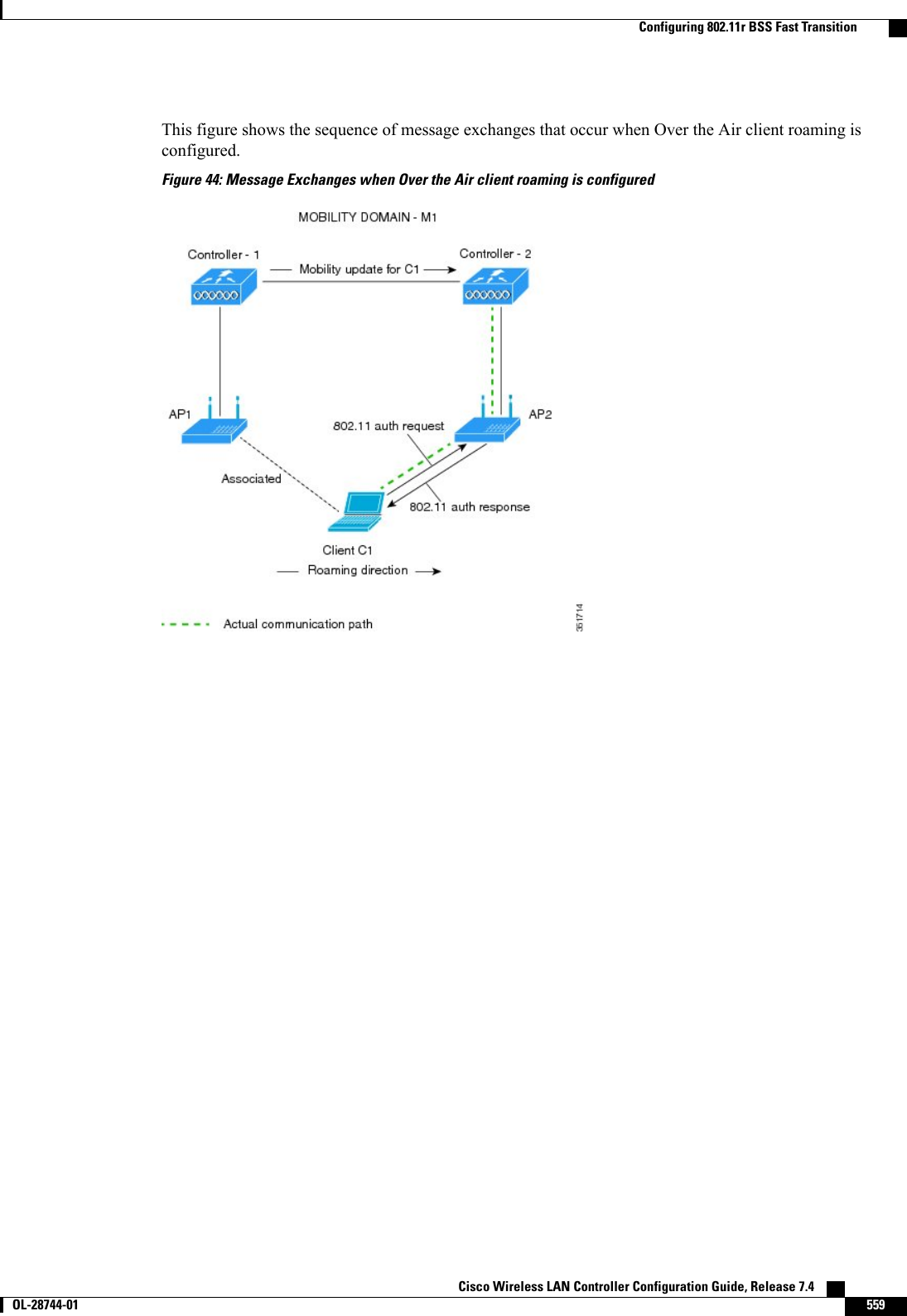
![The controller performs both web authentication and 802.1X authentication in the sameWLAN. The clients are initially authenticated with 802.1X. After a successfulauthentication, the client must provide the web authentication credentials. After asuccessful web authentication, the client is moved to the run state.Note•Change the 802.1X encryption level for a WLAN by entering this command:config wlan security 802.1X encryption wlan_id [0 | 40 | 104]◦Use the 0option to specify no 802.1X encryption.◦Use the 40 option to specify 40/64-bit encryption.◦Use the 104 option to specify 104/128-bit encryption. (This is the default encryption setting.)Configuring 802.11r BSS Fast TransitionRestrictions for 802.11r Fast Transition•This feature is not supported on Mesh access points.•For the access points in FlexConnect mode:•802.11r Fast Transition is supported only in central and locally switched WLANs.•This feature is not supported for the WLANs enabled for local authentication.•This feature is not supported on Linux-based APs such as Cisco 600 Series OfficeExtend Access Points.•802.11r client association is not supported on access points in standalone mode.•802.11r fast roaming is not supported on access points in standalone mode.•802.11r fast roaming between local authentication and central authentication WLAN is not supported.•802.11r fast roaming is not supported if the client uses Over-the-DS preauthentication in standalonemode.•EAP LEAP method is not supported. WAN link latency prevents association time to a maximum of 2seconds.•The service from standalone AP to client is only supported until the session timer expires.•TSpec is not supported for 802.11r fast roaming. Therefore, RIC IE handling is not supported.•If WAN link latency exists, fast roaming is also delayed. Voice or data maximum latency should beverified. The controller handles 802.11r Fast Transition authentication request during roaming for bothOver-the-Air and Over-the-DS methods.•This feature is supported only on open and WPA2 configured WLANs.•Legacy clients cannot associate with a WLAN that has 802.11r enabled if the driver of the supplicantthat is responsible for parsing the Robust Security Network Information Exchange (RSN IE) is old andCisco Wireless LAN Controller Configuration Guide, Release 7.4 OL-28744-01 557Configuring 802.11r BSS Fast Transition](https://usermanual.wiki/Cisco-Systems/102087P.Wireless-LAN-Controller-Configuration-Guide-Part2/User-Guide-2323188-Page-263.png)
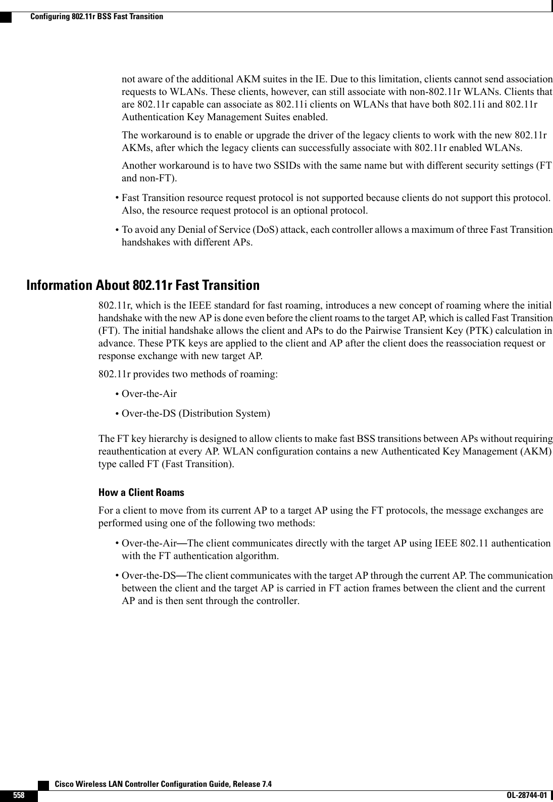


![CHAPTER 80Configuring CKIP•Information About CKIP, page 575•Configuring CKIP (GUI), page 576•Configuring CKIP (CLI), page 576Information About CKIPCisco Key Integrity Protocol (CKIP) is a Cisco-proprietary security protocol for encrypting 802.11 media.CKIP improves 802.11 security in infrastructure mode using key permutation, a message integrity check(MIC), and a message sequence number. Software release 4.0 or later releases support CKIP with a static key.For this feature to operate correctly, you must enable Aironet information elements (IEs) for the WLAN.A lightweight access point advertises support for CKIP in beacon and probe response packets by adding anAironet IE and setting one or both of the CKIP negotiation bits (key permutation and multi-modular hashmessage integrity check [MMH MIC]). Key permutation is a data encryption technique that uses the basicencryption key and the current initialization vector (IV) to create a new key. MMH MIC prevents bit-flipattacks on encrypted packets by using a hash function to compute message integrity code.The CKIP settings specified in a WLAN are mandatory for any client attempting to associate. If the WLANis configured for both CKIP key permutation and MMH MIC, the client must support both. If the WLAN isconfigured for only one of these features, the client must support only the CKIP feature.CKIP requires that 5-byte and 13-byte encryption keys be expanded to 16-byte keys. The algorithm to performkey expansion occurs at the access point. The key is appended to itself repeatedly until the length reaches 16bytes. All lightweight access points support CKIP.CKIP is supported for use only with static WEP. It is not supported for use with dynamic WEP. Therefore,a wireless client that is configured to use CKIP with dynamic WEP is unable to associate to a WLAN thatis configured for CKIP. We recommend that you use either dynamic WEP without CKIP (which is lesssecure) or WPA/WPA2 with TKIP or AES (which are more secure).NoteCisco Wireless LAN Controller Configuration Guide, Release 7.4 OL-28744-01 575](https://usermanual.wiki/Cisco-Systems/102087P.Wireless-LAN-Controller-Configuration-Guide-Part2/User-Guide-2323188-Page-281.png)


![The conditional web redirect feature is available only for WLANs that are configured for 802.1X orWPA+WPA2 Layer 2 security.NoteAfter you configure the RADIUS server, you can then configure the conditional web redirect on the controllerusing either the controller GUI or CLI.Splash Page Web RedirectIf you enable splash page web redirect, the user is redirected to a particular web page after 802.1X authenticationhas completed successfully. After the redirect, the user has full access to the network. You can specify theredirect page on your RADIUS server. If the RADIUS server returns the Cisco AV-pair “url-redirect,”thenthe user is redirected to the specified URL upon opening a browser. The client is considered fully authorizedat this point and is allowed to pass traffic, even if the RADIUS server does not return a “url-redirect.”The splash page web redirect feature is available only for WLANs that are configured for 802.1X orWPA+WPA2 Layer 2 security with 802.1x key management. Preshared key management is not supportedwith any Layer 2 security method.NoteSuppose there are backend applications running on the wireless clients and they use HTTP or HTTPS portfor their communication. If the applications start communicating before the actual web page is opened, theredirect functionality does not work with web passthrough.After you configure the RADIUS server, you can then configure the splash page web redirect on the controllerusing either the controller GUI or CLI.Configuring the RADIUS Server (GUI)These instructions are specific to the CiscoSecure ACS; however, they should be similar to those for otherRADIUS servers.NoteStep 1 From the CiscoSecure ACS main menu, choose Group Setup.Step 2 Click Edit Settings.Step 3 From the Jump To drop-down list, choose RADIUS (Cisco IOS/PIX 6.0).Step 4 Select the [009\001] cisco-av-pair check box.Step 5 Enter the following Cisco AV-pairs in the [009\001] cisco-av-pair edit box to specify the URL to which the user isredirected and, if configuring conditional web redirect, the conditions under which the redirect takes place, respectively:url-redirect=http://urlurl-redirect-acl=acl_name Cisco Wireless LAN Controller Configuration Guide, Release 7.4638 OL-28744-01 Configuring the RADIUS Server (GUI)](https://usermanual.wiki/Cisco-Systems/102087P.Wireless-LAN-Controller-Configuration-Guide-Part2/User-Guide-2323188-Page-344.png)