Cisco Systems 102087P Cisco Aironet 802.11ac Dual Band Access Points User Manual Wireless LAN Controller Configuration Guide Part3
Cisco Systems Inc Cisco Aironet 802.11ac Dual Band Access Points Wireless LAN Controller Configuration Guide Part3
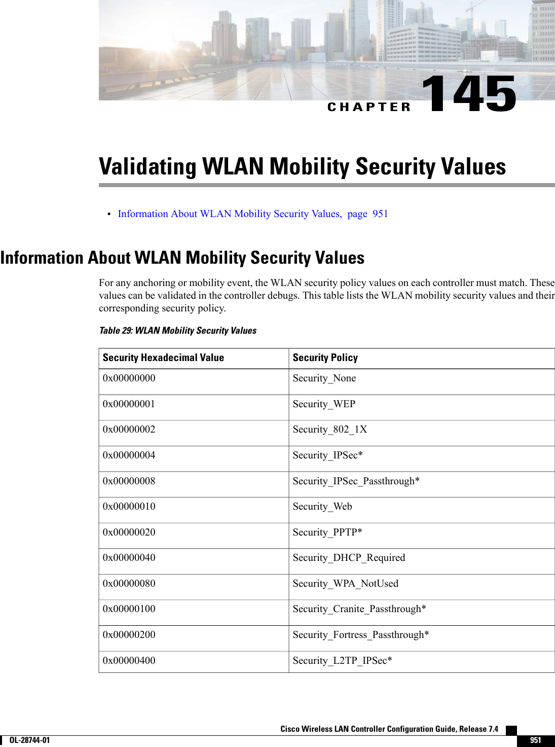
Contents
- 1. Manual
- 2. revised manual
- 3. Wireless LAN Controller Configuration Guide_Part1
- 4. Wireless LAN Controller Configuration Guide_Part2
- 5. Wireless LAN Controller Configuration Guide_Part3
- 6. Wireless LAN Controller Configuration Guide_Part4
Wireless LAN Controller Configuration Guide_Part3

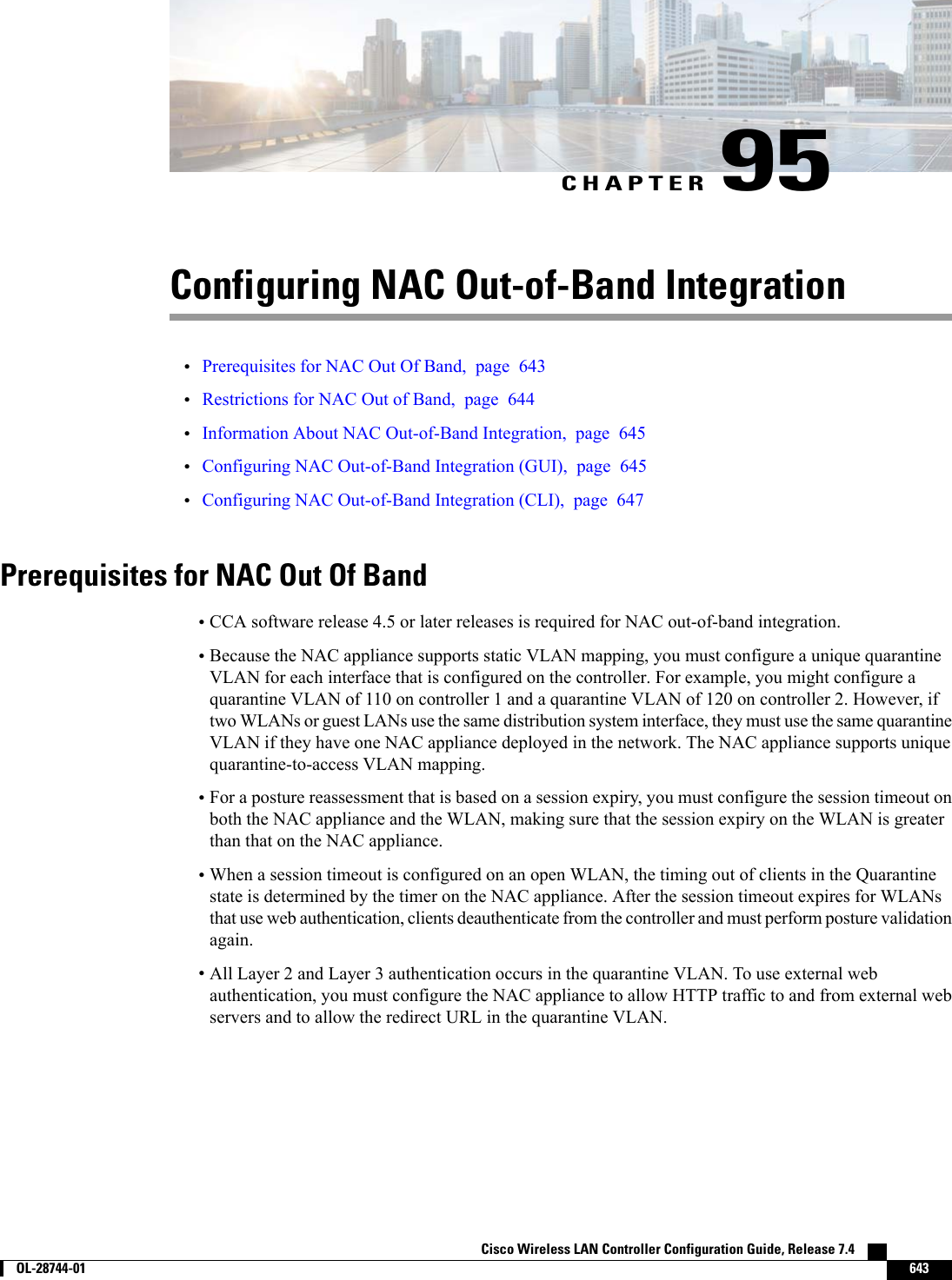
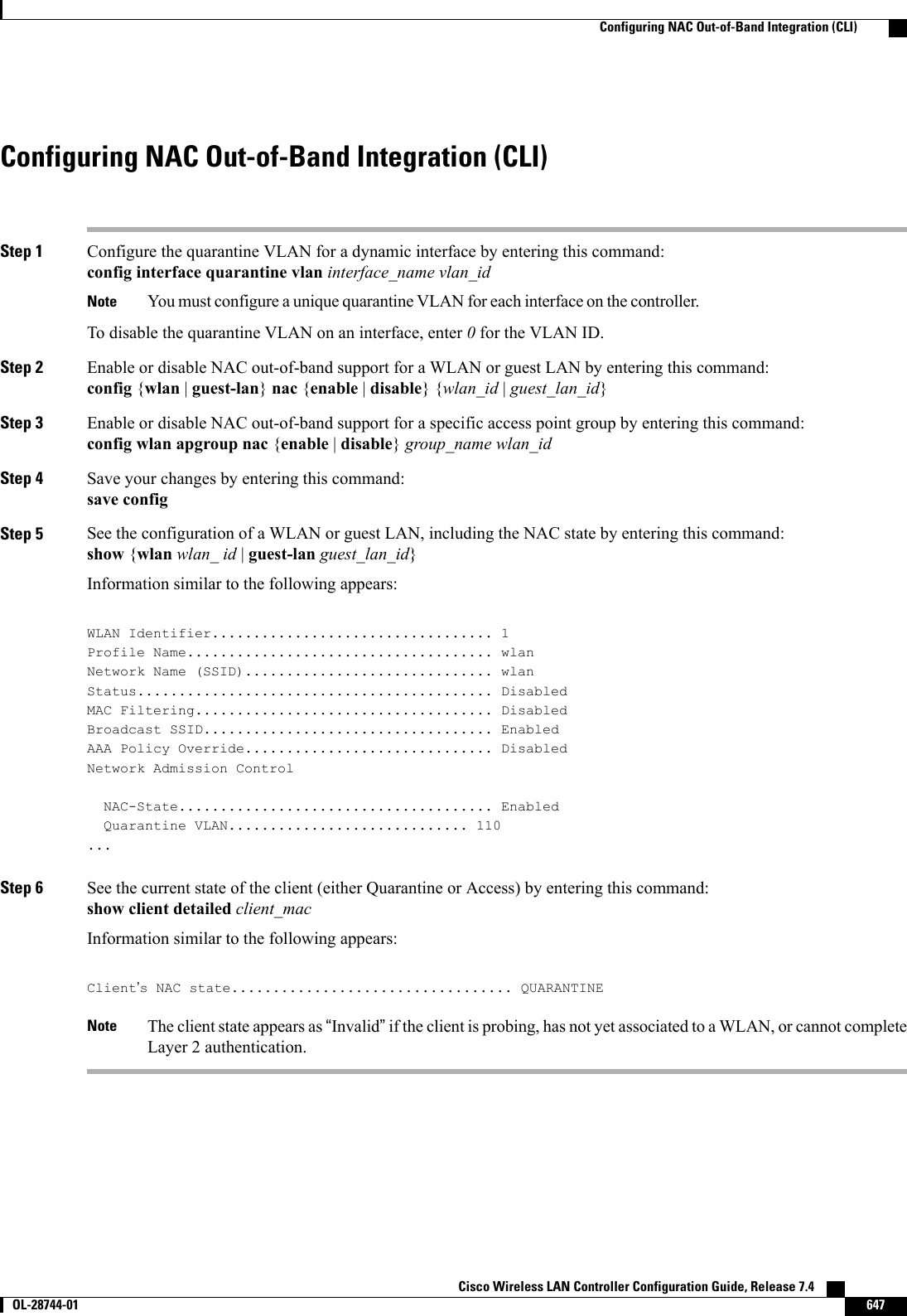


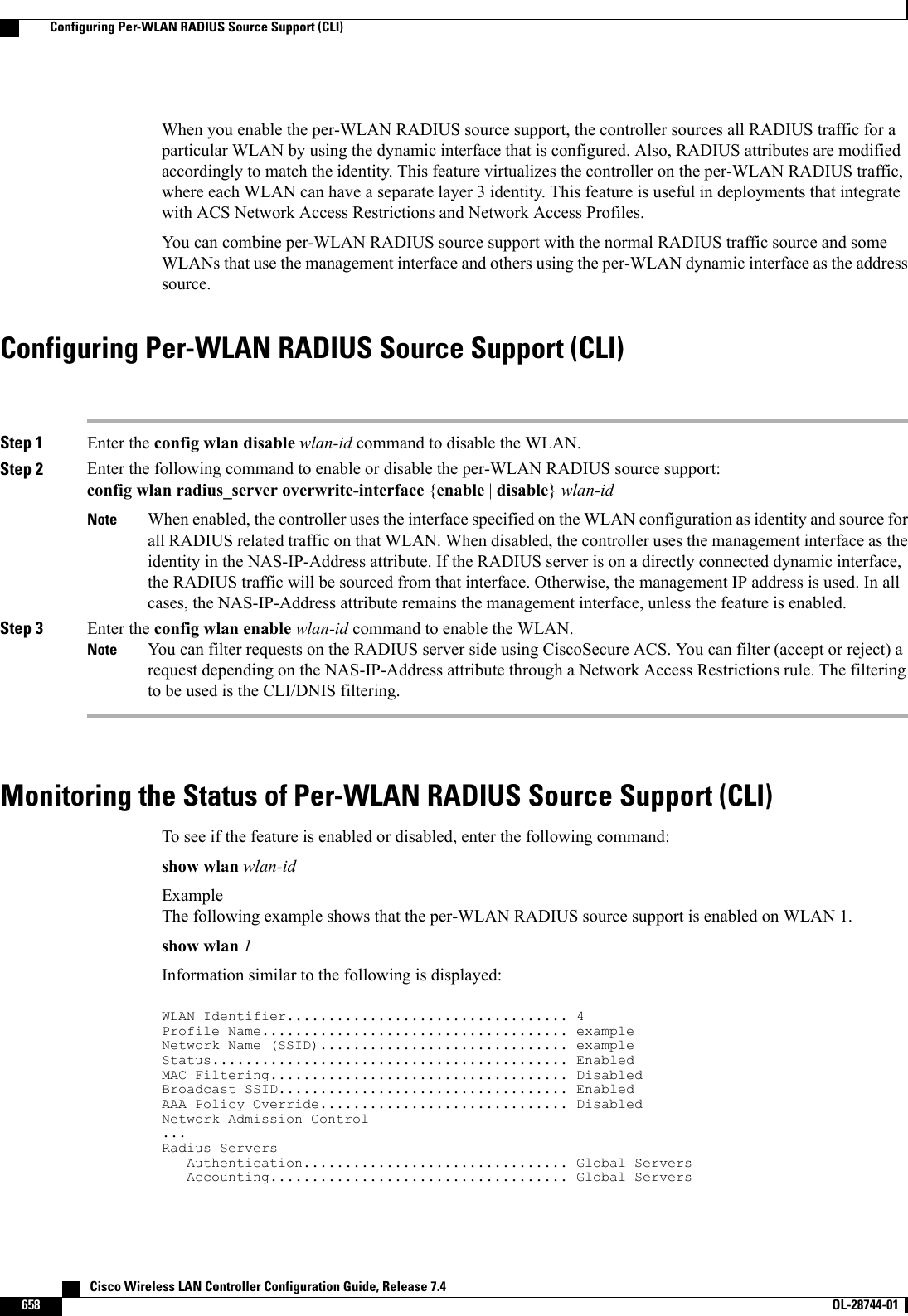


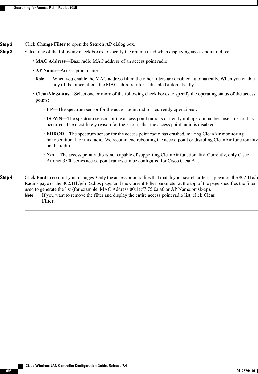
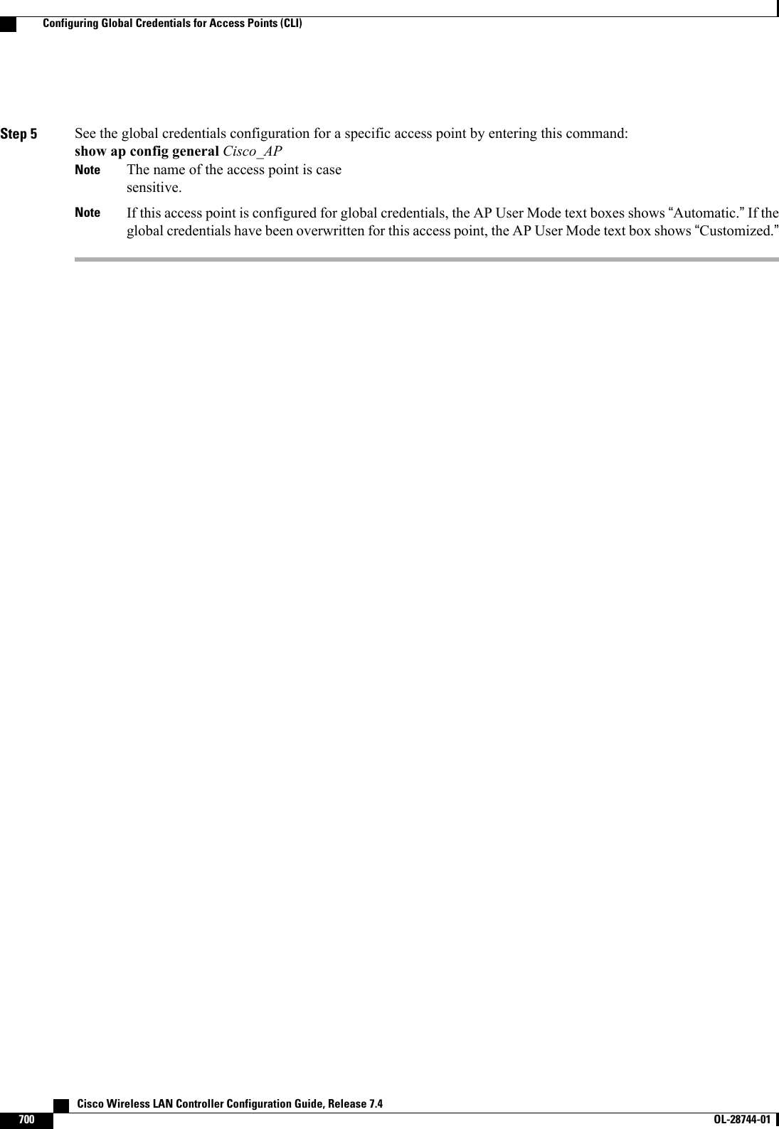
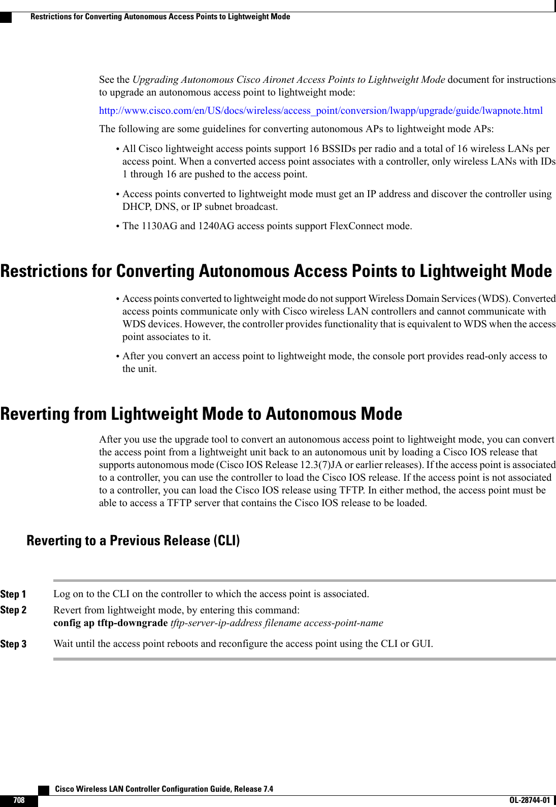
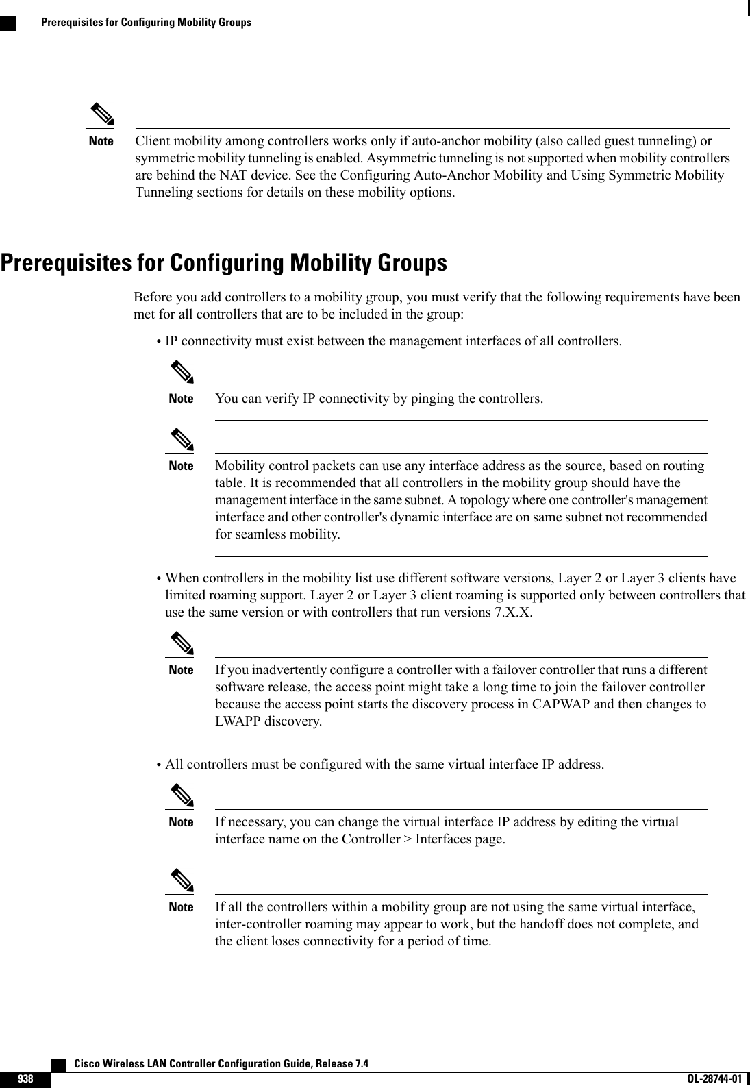
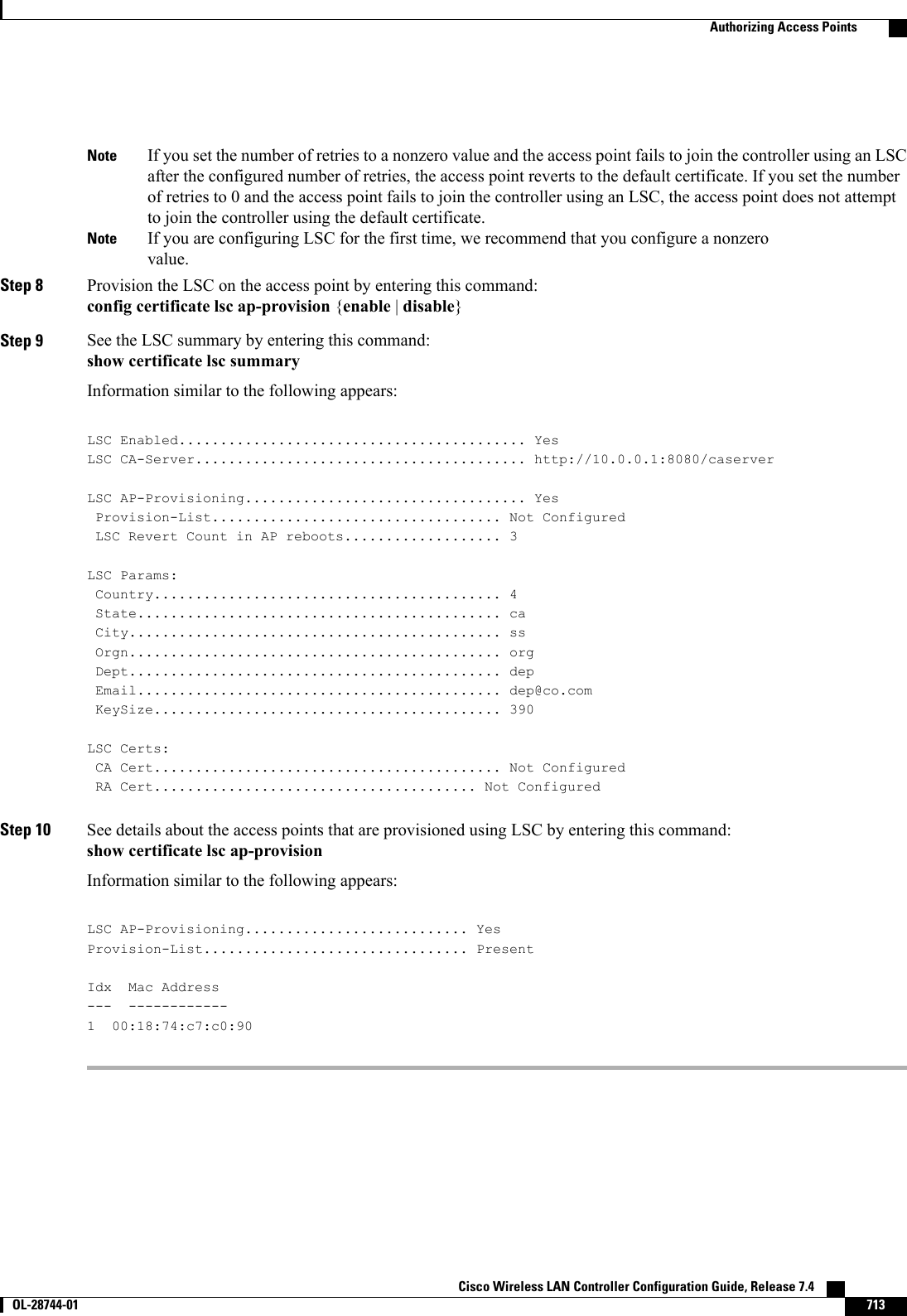
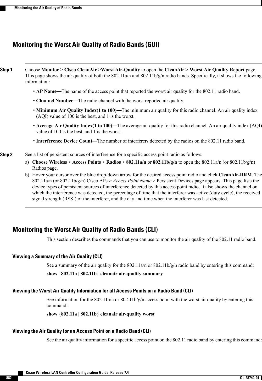
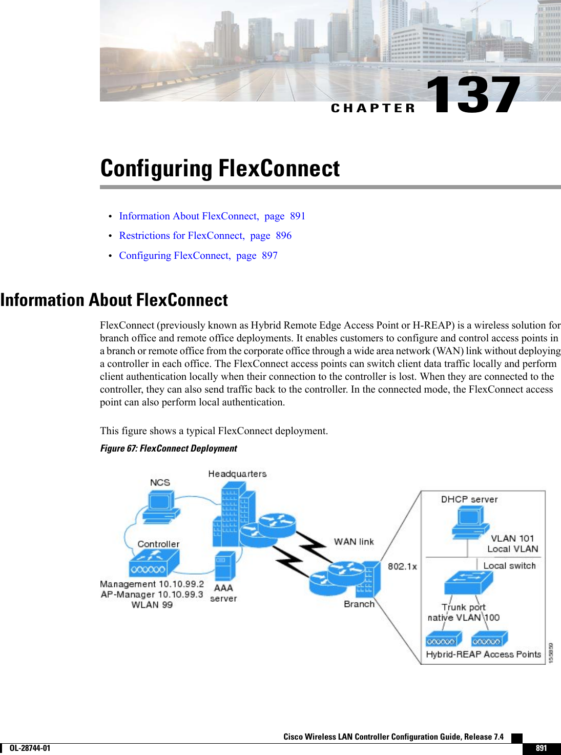
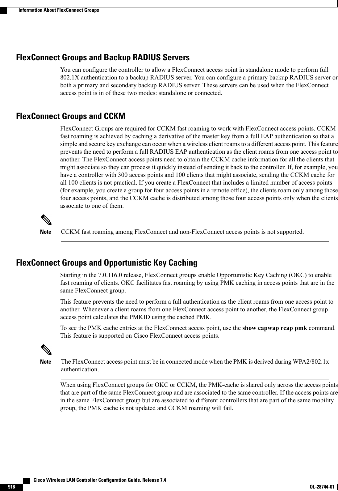
![Reverting to a Previous Release Using the MODE Button and a TFTP ServerStep 1 Configure the PC on which your TFTP server software runs with a static IP address in the range of 10.0.0.2 to 10.0.0.30.Step 2 Make sure that the PC contains the access point image file (such as c1200-k9w7-tar.123-7.JA.tar for a 1200 series accesspoint) in the TFTP server folder and that the TFTP server is activated.Step 3 Rename the access point image file in the TFTP server folder to c1200-k9w7-tar.default for a 1200 series access point.Step 4 Connect the PC to the access point using a Category 5 (CAT5) Ethernet cable.Step 5 Disconnect power from the access point.Step 6 Press and hold the MODE button while you reconnect power to the access point.The MODE button on the access point must be enabled. Follow the steps in the Disabling the Reset Button onAccess Points Converted to Lightweight Mode to select the status of the access point MODE button.NoteStep 7 Hold the MODE button until the status LED turns red (approximately 20 to 30 seconds), and release the MODE button.Step 8 Wait until the access point reboots as indicated by all LEDs turning green followed by the Status LED blinking green.Step 9 After the access point reboots, reconfigure the access point using the GUI or the CLI.Authorizing Access PointsIn controller software releases prior to 5.2, the controller may either use self-signed certificates (SSCs) toauthenticate access points or send the authorization information to a RADIUS server (if access points havemanufactured-installed certificates [MICs]). In controller software release 5.2 or later releases, you canconfigure the controller to use a local significant certificate (LSC).Authorizing Access Points Using SSCsThe Control and Provisioning of Wireless Access Points protocol (CAPWAP) secures the controlcommunication between the access point and controller by a secure key distribution requiring X.509 certificateson both the access point and controller. CAPWAP relies on provisioning of the X.509 certificates. CiscoAironet access points shipped before July 18, 2005 do not have a MIC, so these access points create an SSCwhen upgraded to operate in lightweight mode. Controllers are programmed to accept local SSCs forauthentication of specific access points and do not forward those authentication requests to a RADIUS server.This behavior is acceptable and secure.Authorizing Access Points for Virtual Controllers Using SSCVirtual controllers use SSC certificates instead of Manufacturing Installed Certificates (MIC) used by physicalcontrollers. You can configure the controller to allow an AP to validate the SSC of the virtual controller.When an AP validates the SSC, the AP checks if the hash key of the virtual controller matches the hash keystored in its flash. If a match is found, the AP associates with the controller. If a match is not found, thevalidation fails and the AP disconnects from the controller and restarts the discovery process. By default, hashvalidation is enabled. An AP must have the virtual controller hash key in its flash before associating with thevirtual controller. If you disable hash validation of the SSC, the AP bypasses the hash validation and directlymoves to the Run state. APs can associate with a physical controller, download the hash keys and then associateCisco Wireless LAN Controller Configuration Guide, Release 7.4 OL-28744-01 709Authorizing Access Points](https://usermanual.wiki/Cisco-Systems/102087P.Wireless-LAN-Controller-Configuration-Guide-Part3/User-Guide-2323189-Page-71.png)
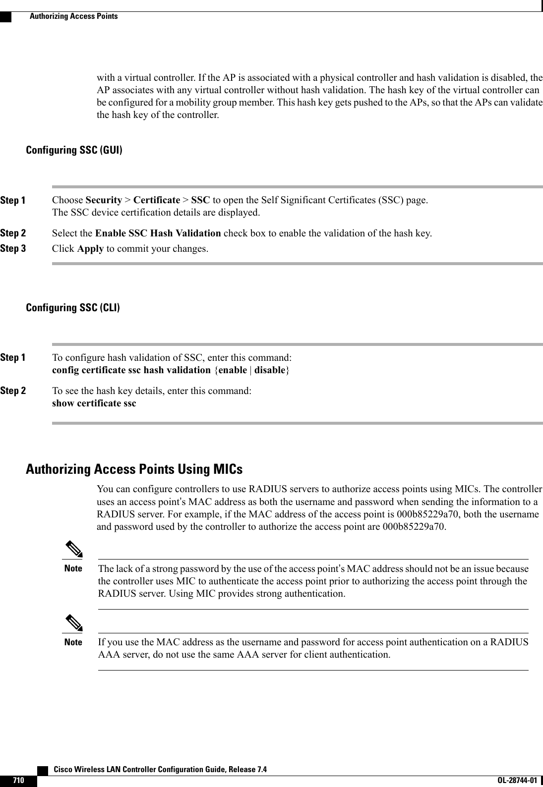
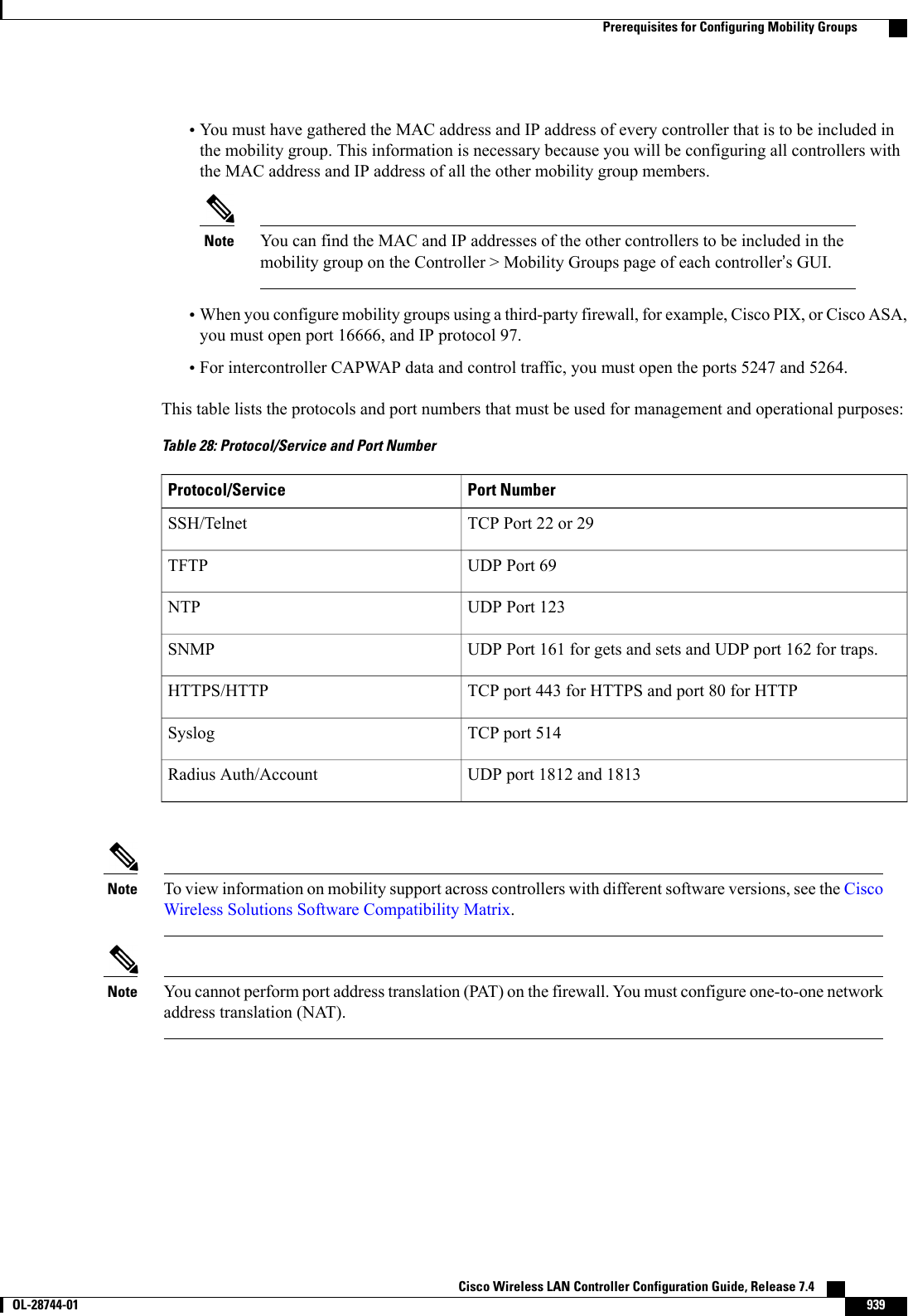
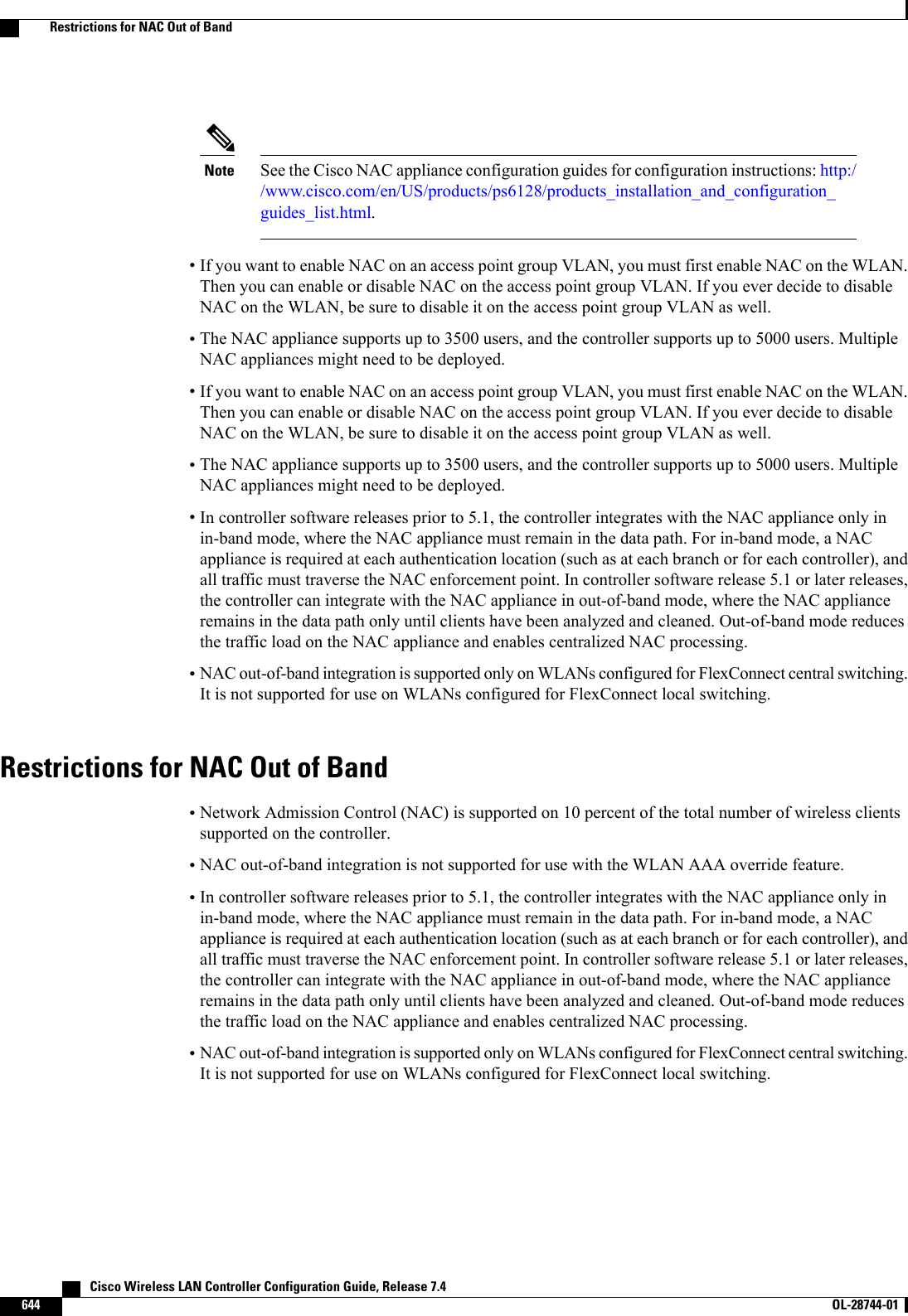
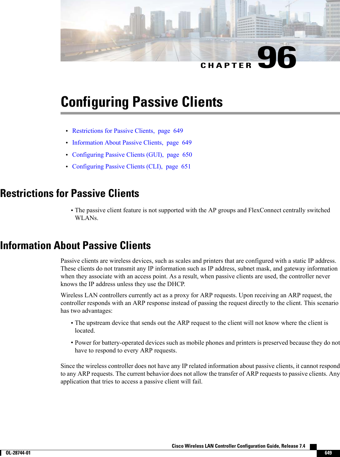
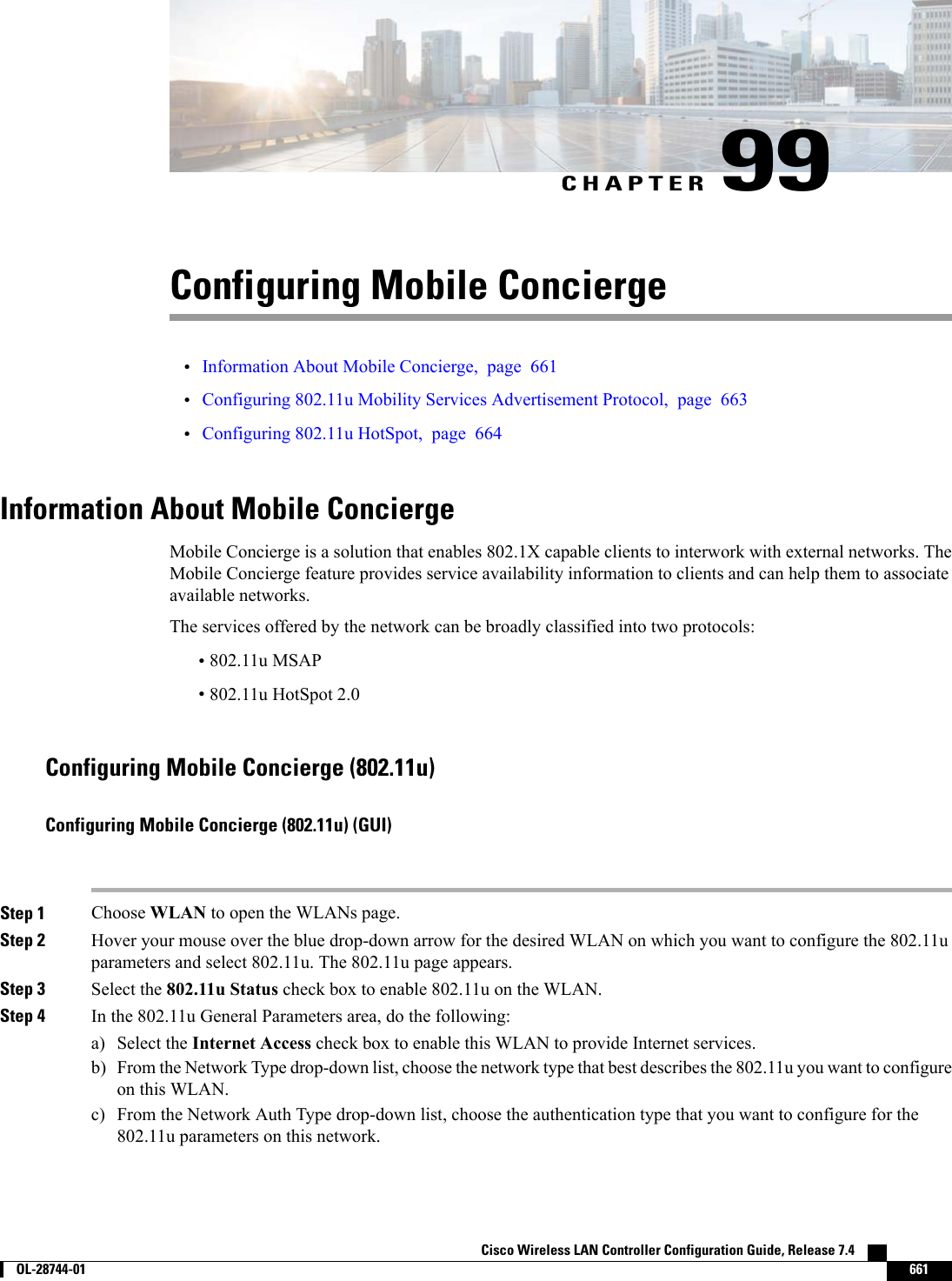
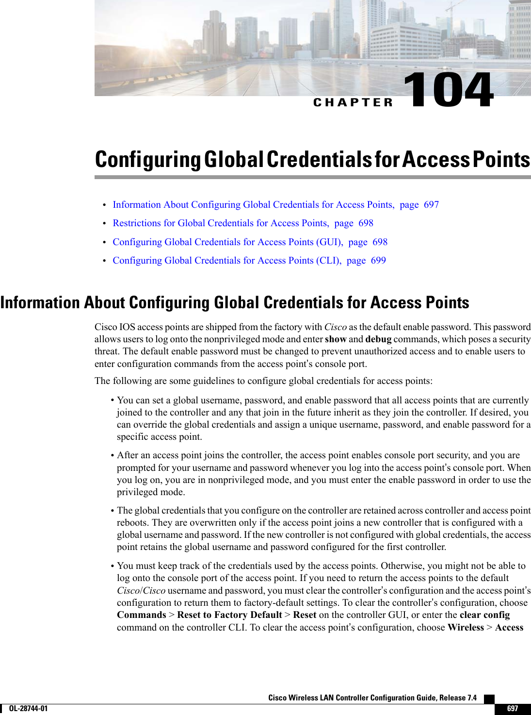
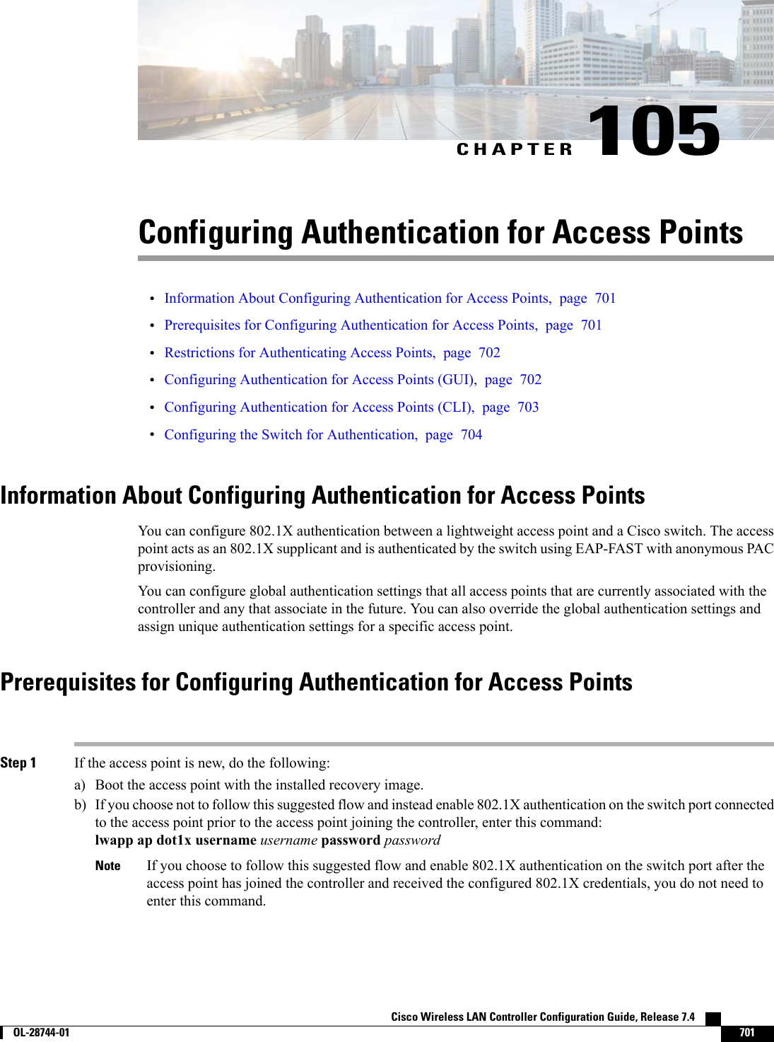
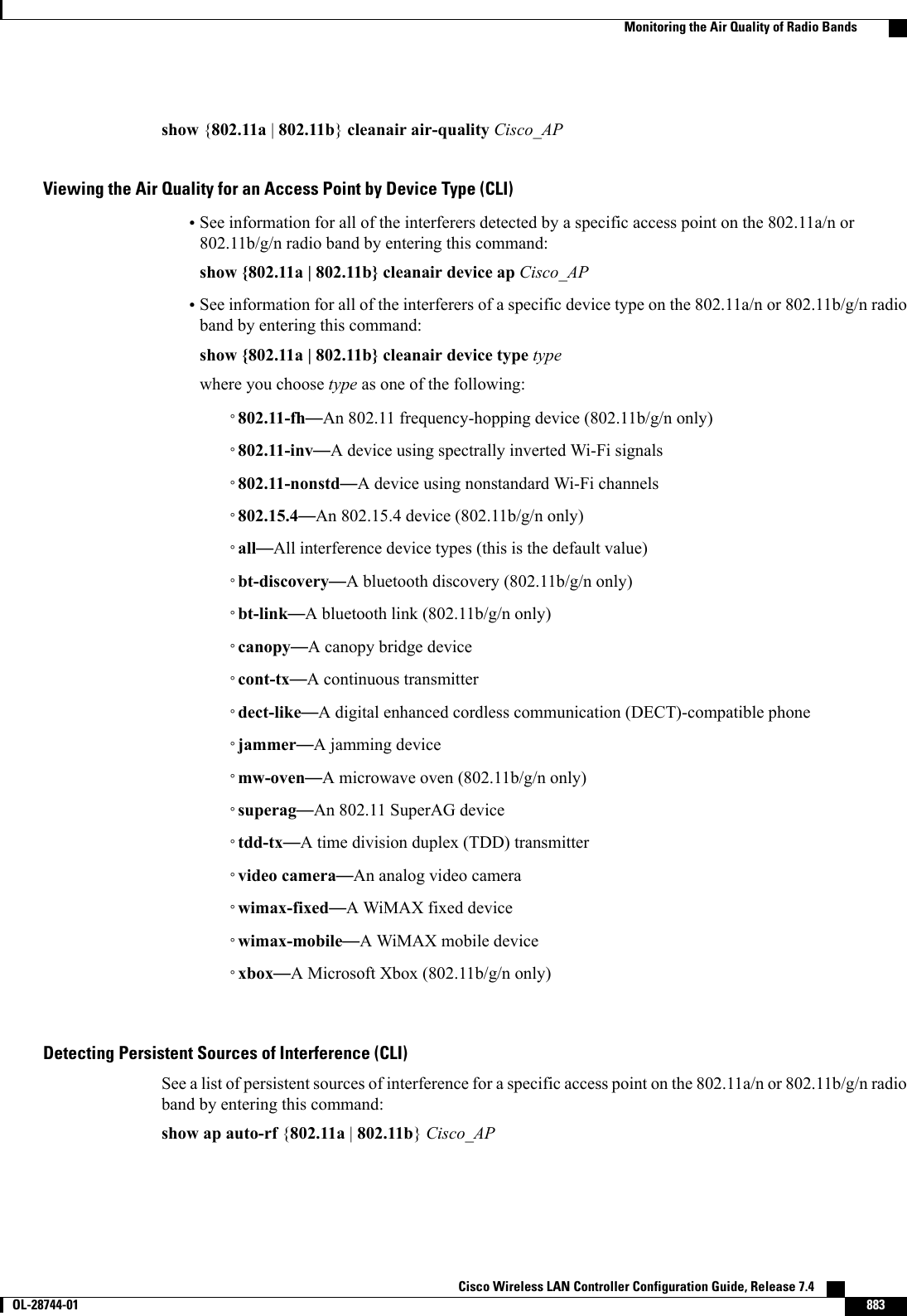
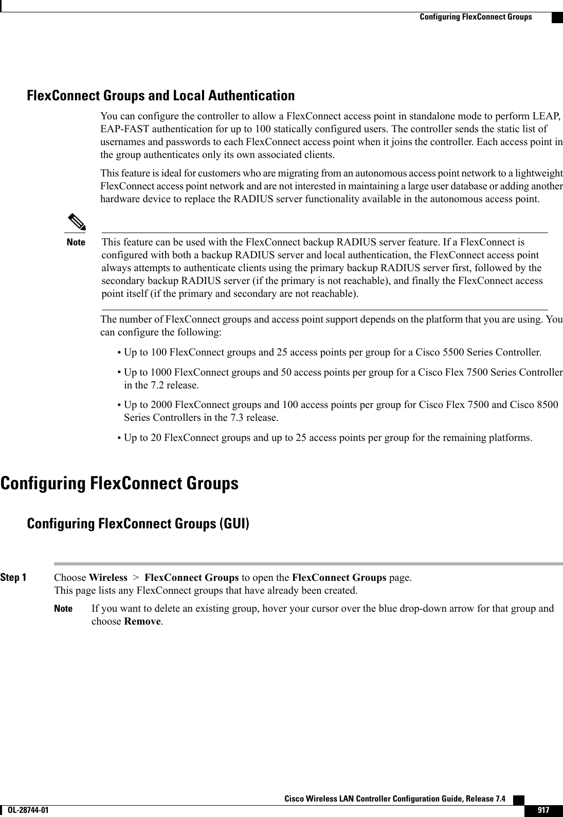
![Authorizing Access Points (GUI)Step 1 Choose Security >AAA >AP Policies to open the AP Policies page.Step 2 If you want the access point to accept self-signed certificates (SSCs), manufactured-installed certificates (MICs), or localsignificant certificates (LSCs), select the appropriate check box.Step 3 If you want the access points to be authorized using a AAA RADIUS server, select the Authorize MIC APs againstauth-list or AAA check box.Step 4 If you want the access points to be authorized using an LSC, select the Authorize LSC APs against auth-list checkbox.Step 5 Click Apply to commit your changes.Step 6 Follow these steps to add an access point to the controller’s authorization list:a) Click Add to access the Add AP to Authorization List area.b) In the MAC Address text box, enter the MAC address of the access point.c) From the Certificate Type drop-down list, choose MIC,SSC, or LSC.d) Click Add. The access point appears in the access point authorization list.To remove an access point from the authorization list, hover your cursor over the blue drop-down arrow forthe access point and choose Remove.NoteTo search for a specific access point in the authorization list, enter the MAC address of the access point inthe Search by MAC text box and click Search.NoteAuthorizing Access Points (CLI)•Configure an access point authorization policy by entering this command:config auth-list ap-policy {authorize-ap {enable |disable} | authorize-lsc-ap {enable |disable}}•Configure an access point to accept manufactured-installed certificates (MICs), self-signed certificates(SSCs), or local significant certificates (LSCs) by entering this command:config auth-list ap-policy {mic | ssc |lsc {enable |disable}}•Configure the user name to be used in access point authorization requests.config auth-list ap-policy {authorize-ap username {ap_name |ap_mac |both}}•Add an access point to the authorization list by entering this command:config auth-list add {mic |ssc |lsc}ap_mac [ap_key]where ap_key is an optional key hash value equal to 20 bytes or 40 digits.To delete an access point from the authorization list, enter this command: config auth-list delete ap_mac.Note•See the access point authorization list by entering this command:show auth-list Cisco Wireless LAN Controller Configuration Guide, Release 7.4714 OL-28744-01 Authorizing Access Points](https://usermanual.wiki/Cisco-Systems/102087P.Wireless-LAN-Controller-Configuration-Guide-Part3/User-Guide-2323189-Page-76.png)


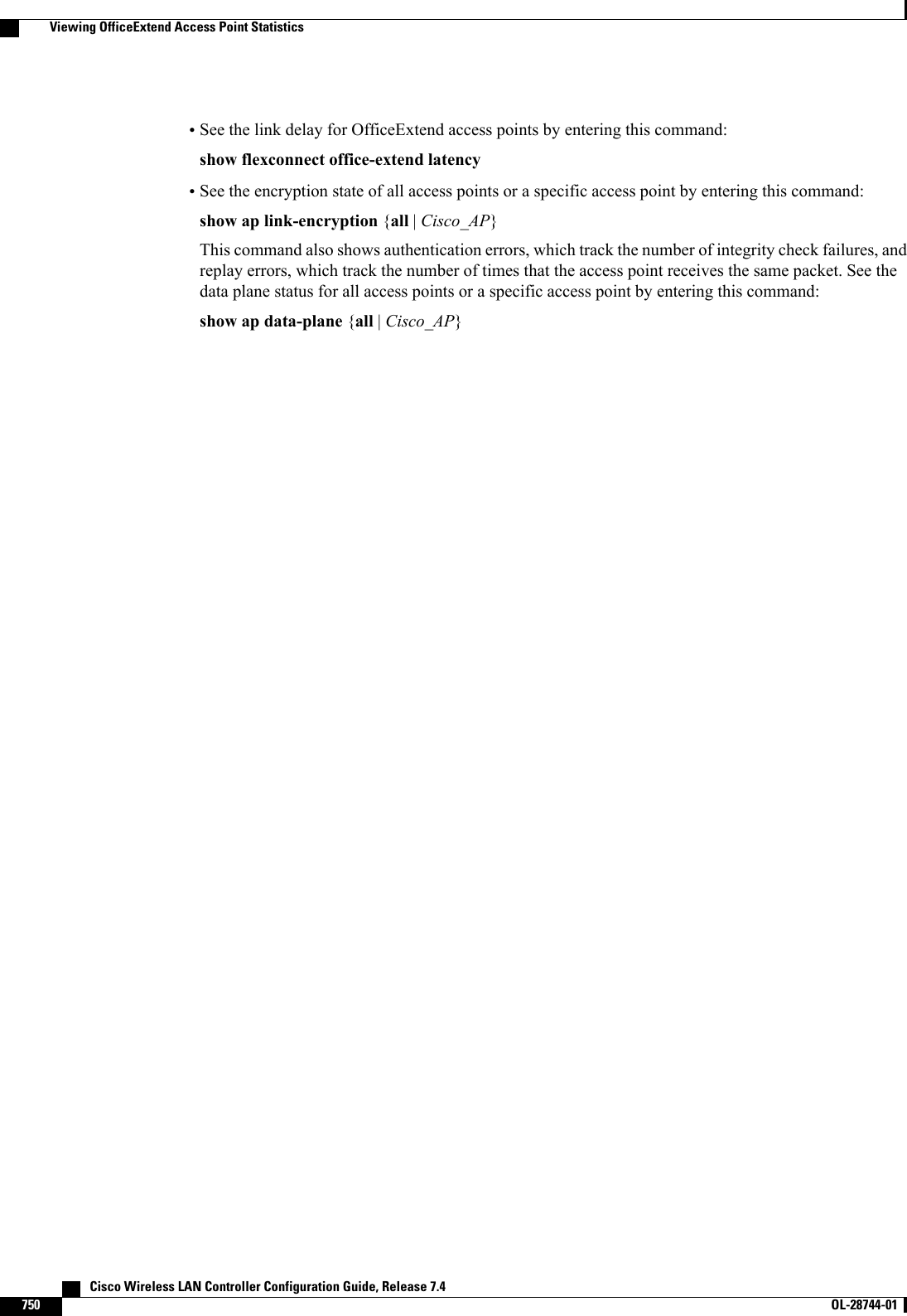
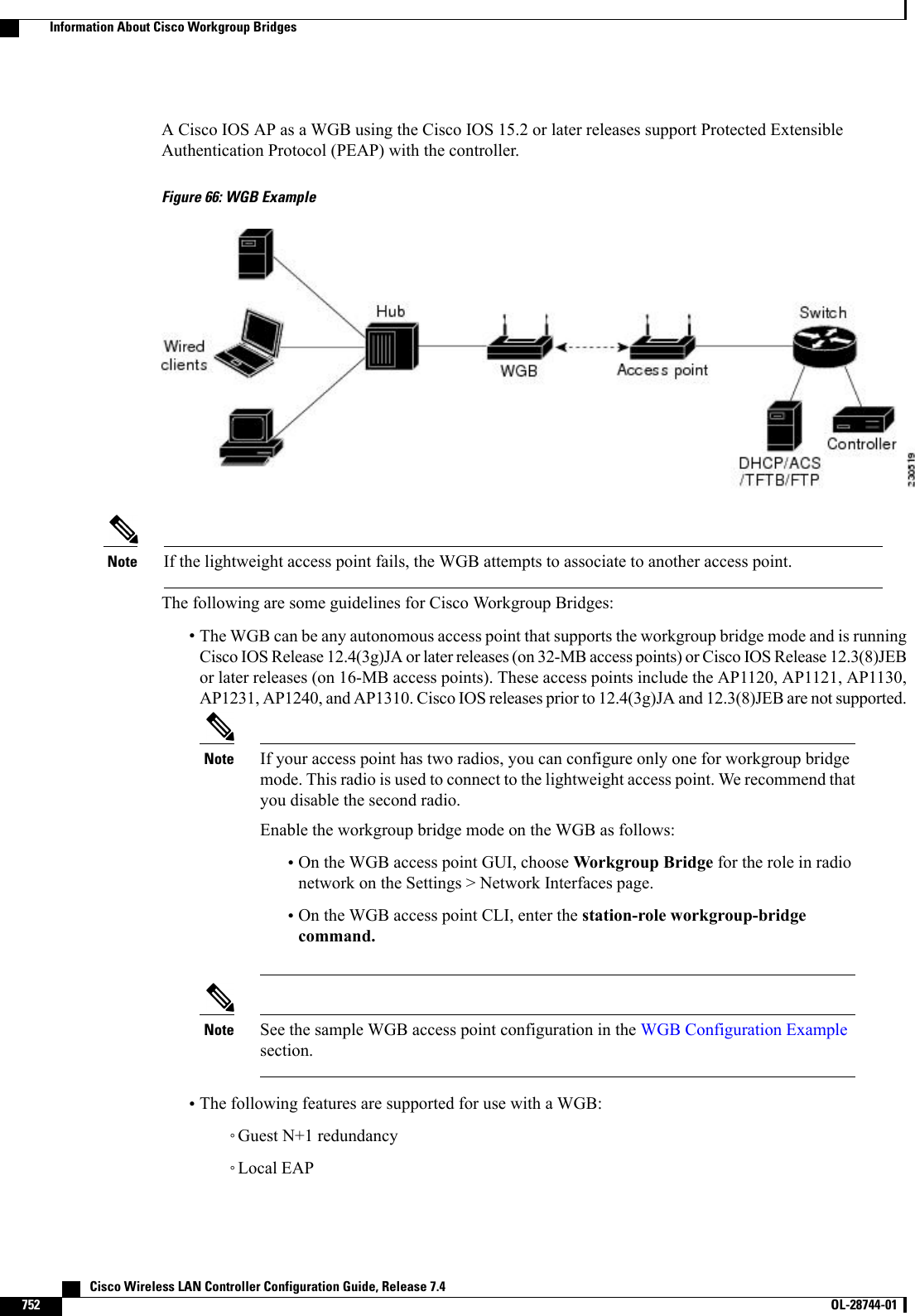
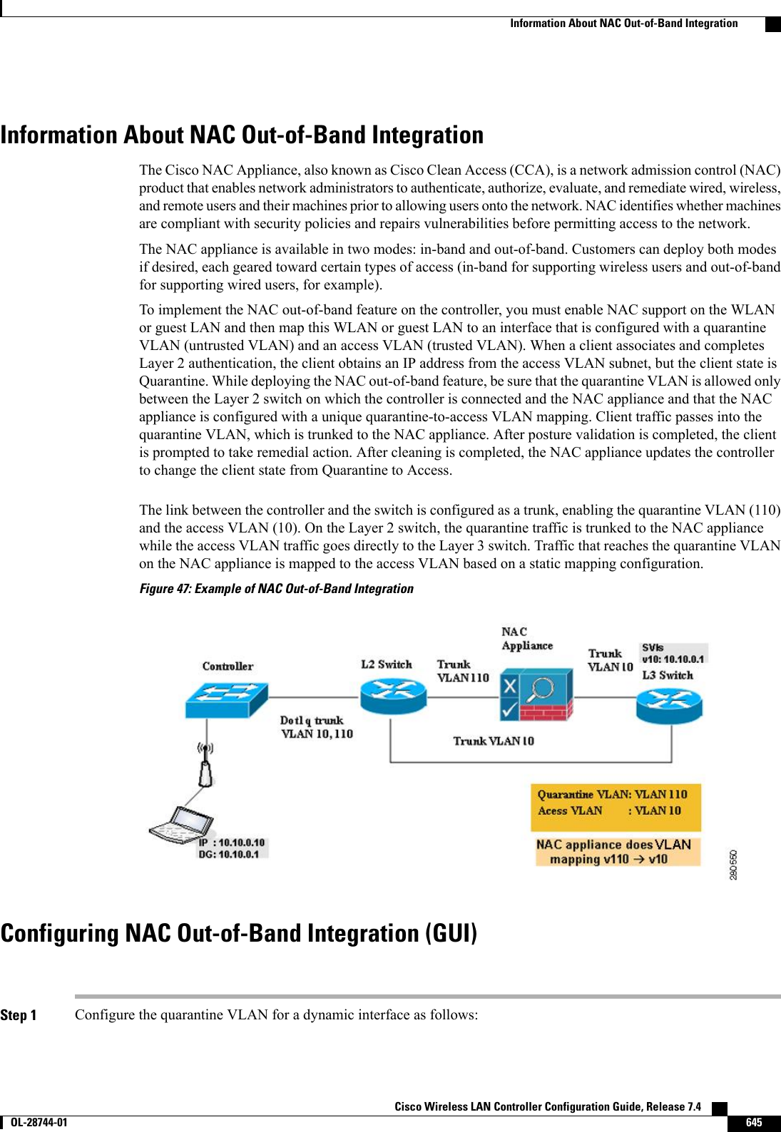
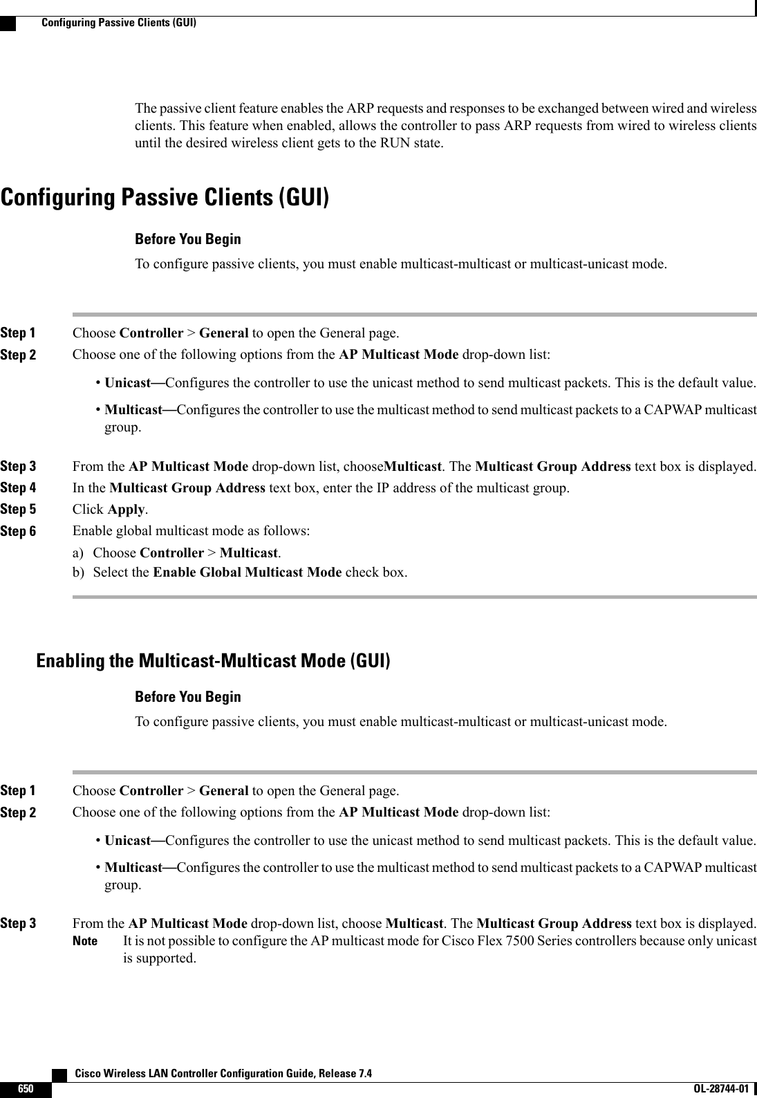
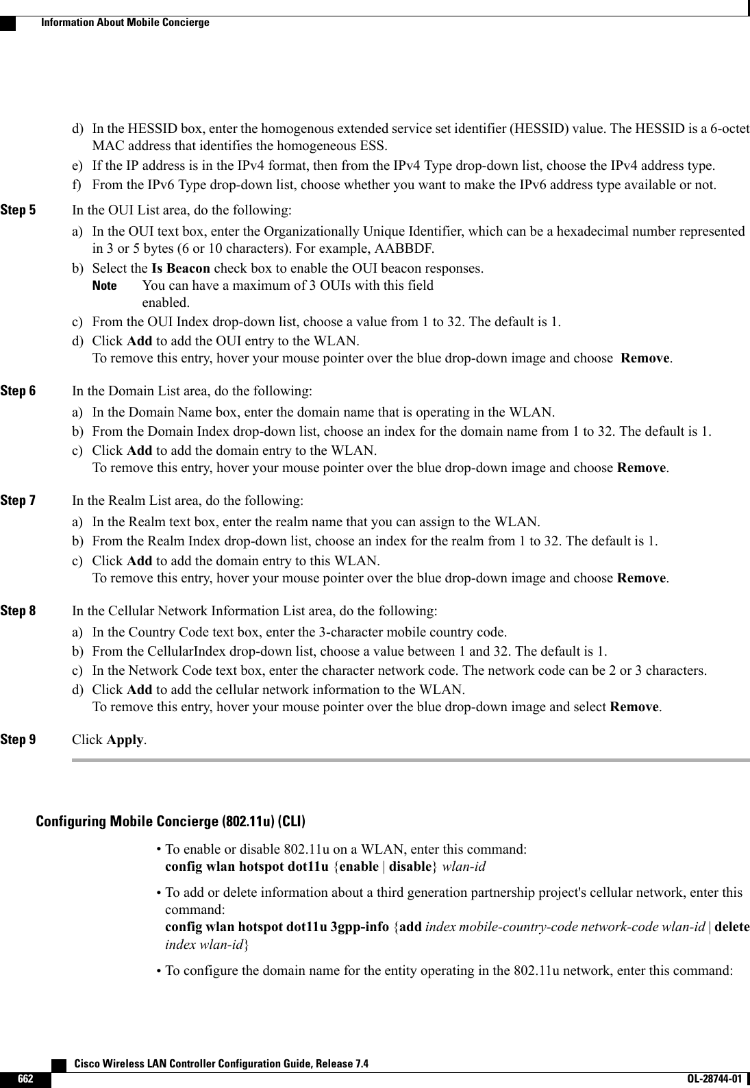
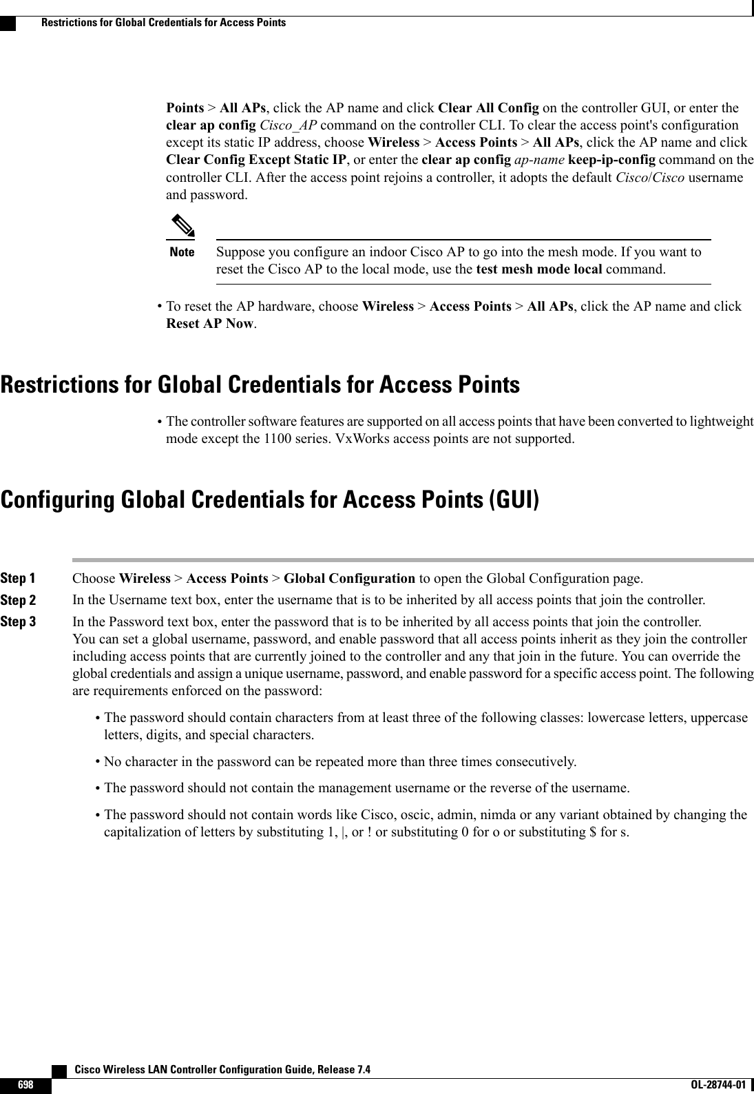
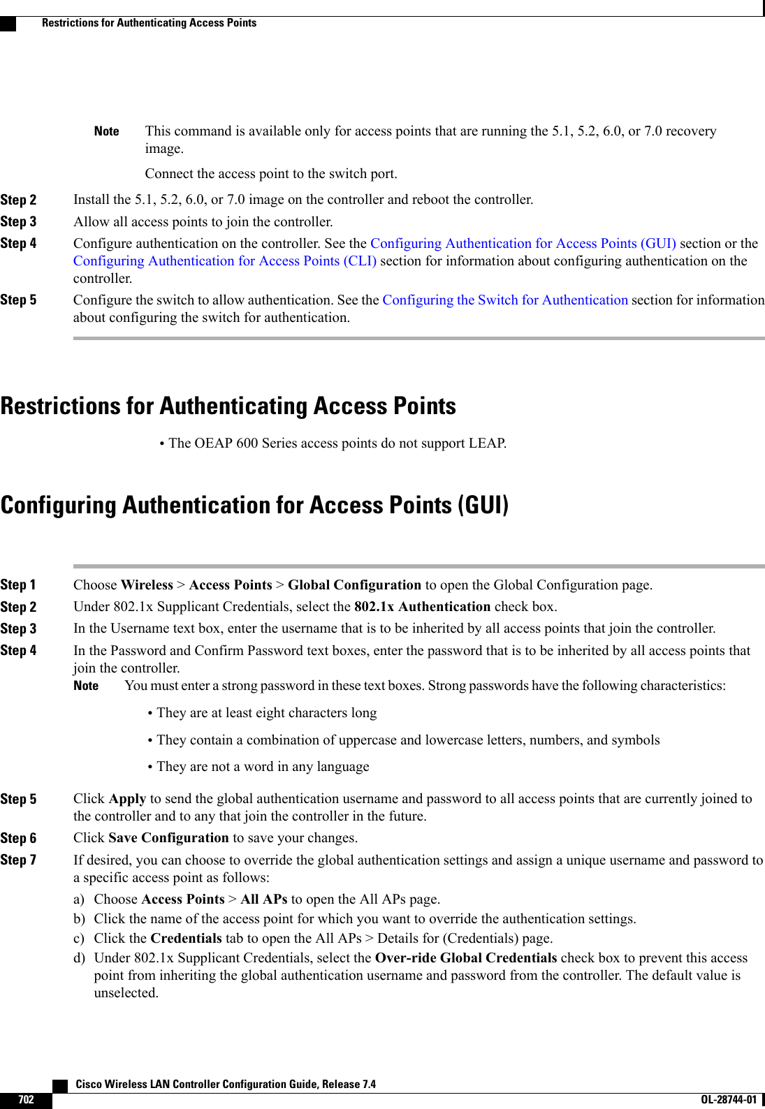
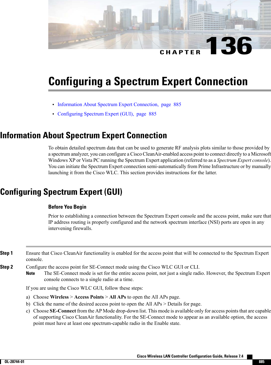
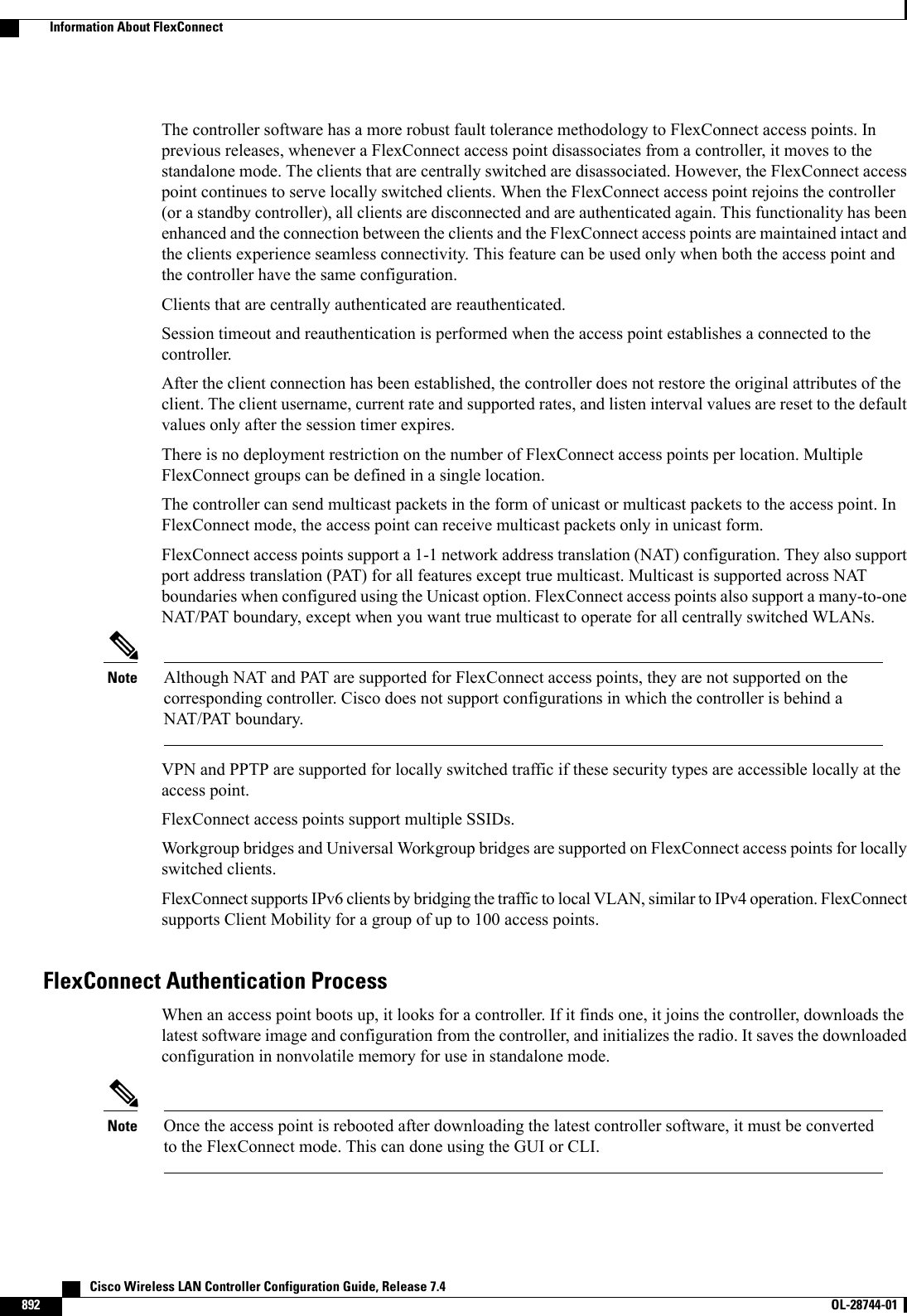
![ap(config-if)# ssid WGB_with_static_WEPap(config-if)# endVerify that the WGB is associated to an access point by entering this command on the WGB:show dot11 associationInformation similar to the following appears:ap# show dot11 associations802.11 Client Stations on Dot11Radio0:SSID [FCVTESTING] :MAC Address IP address Device Name Parent State000b.8581.6aee 10.11.12.1 WGB-client map1 - Assocap#Viewing the Status of Workgroup Bridges (GUI)Step 1 Choose Monitor >Clients to open the Clients page.The WGB text box on the right side of the page indicates whether any of the clients on your network are workgroupbridges.Step 2 Click the MAC address of the desired client. The Clients > Detail page appears.The Client Type text box under Client Properties shows “WGB”if this client is a workgroup bridge, and the Number ofWired Client(s) text box shows the number of wired clients that are connected to this WGB.Step 3 See the details of any wired clients that are connected to a particular WGB as follows:a) Click Back on the Clients > Detail page to return to the Clients page.b) Hover your cursor over the blue drop-down arrow for the desired WGB and choose Show Wired Clients. The WGBWired Clients page appears.If you want to disable or remove a particular client, hover your cursor over the blue drop-down arrow forthe desired client and choose Remove or Disable, respectively.Notec) Click the MAC address of the desired client to see more details for this particular client. The Clients > Detail pageappears.The Client Type text box under Client Properties shows “WGB Client,”and the rest of the text boxes on this pageprovide additional information for this client.Viewing the Status of Workgroup Bridges (CLI)Step 1 See any WGBs on your network by entering this command:show wgb summaryStep 2 See the details of any wired clients that are connected to a particular WGB by entering this command:show wgb detail wgb_mac_addressCisco Wireless LAN Controller Configuration Guide, Release 7.4 OL-28744-01 755Viewing the Status of Workgroup Bridges (GUI)](https://usermanual.wiki/Cisco-Systems/102087P.Wireless-LAN-Controller-Configuration-Guide-Part3/User-Guide-2323189-Page-117.png)
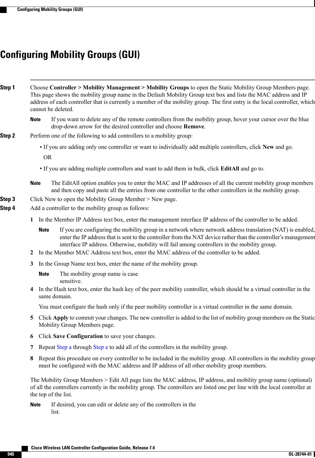
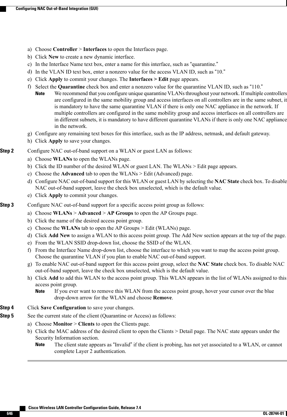
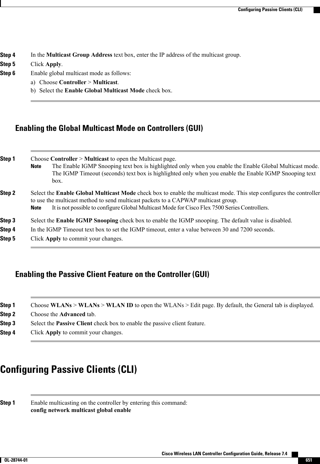
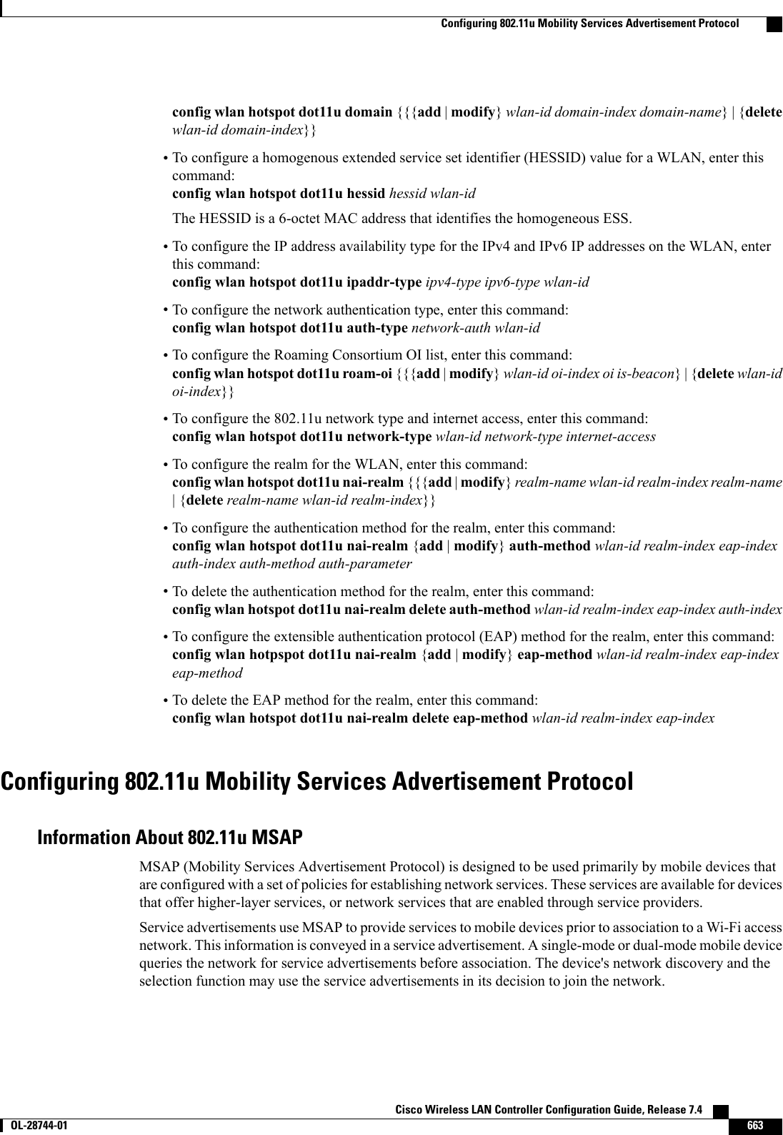
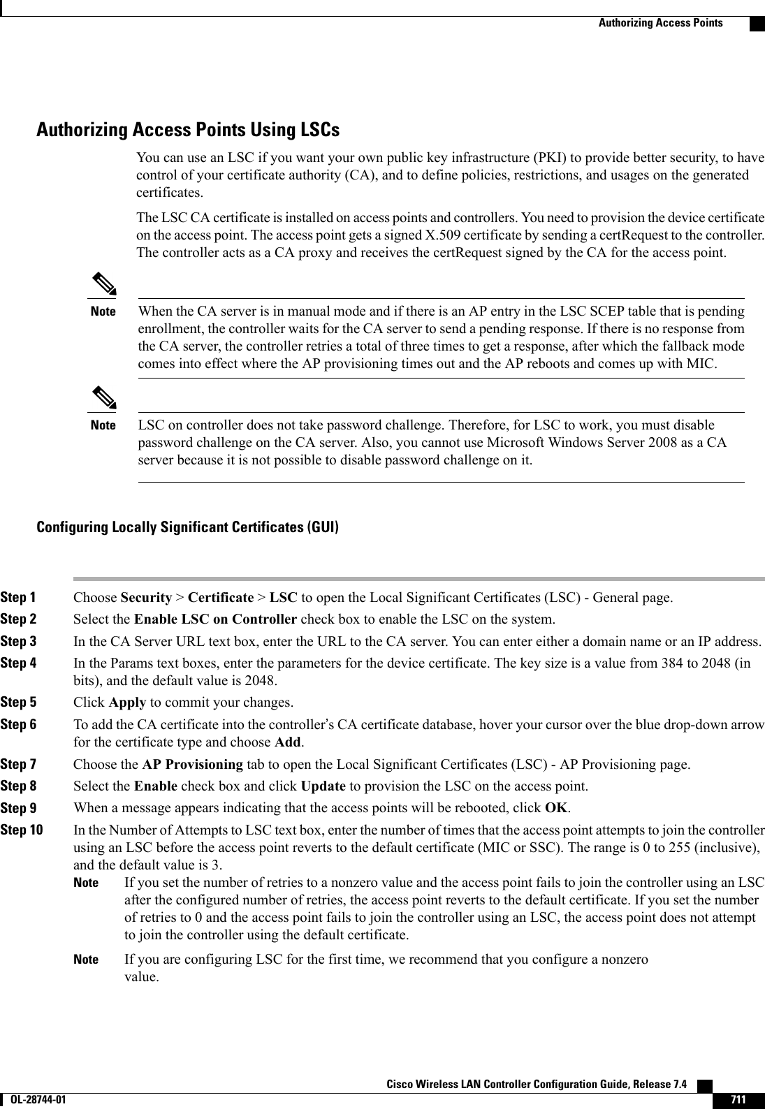
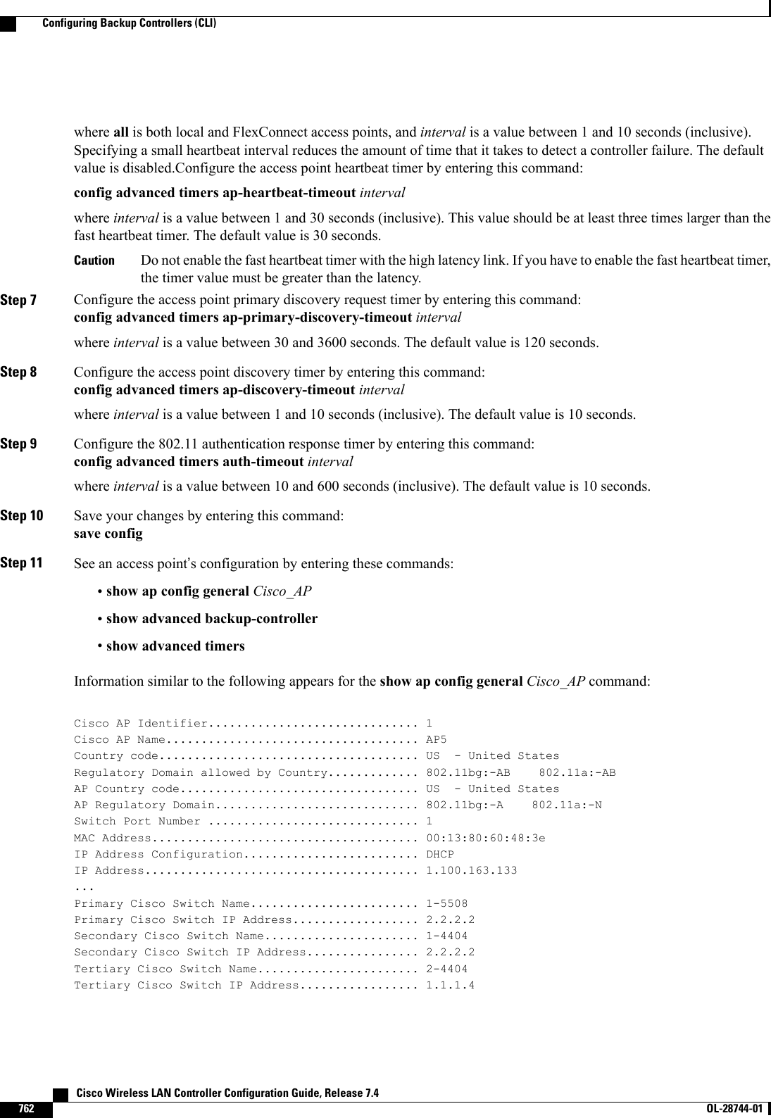
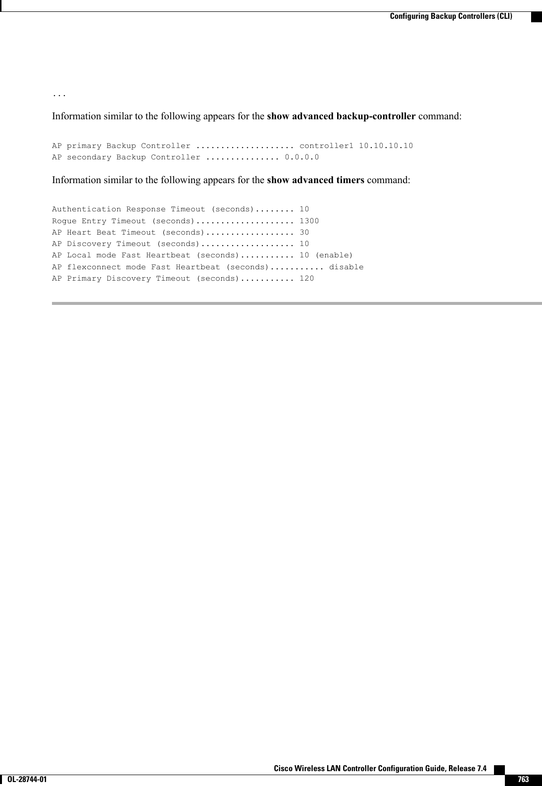
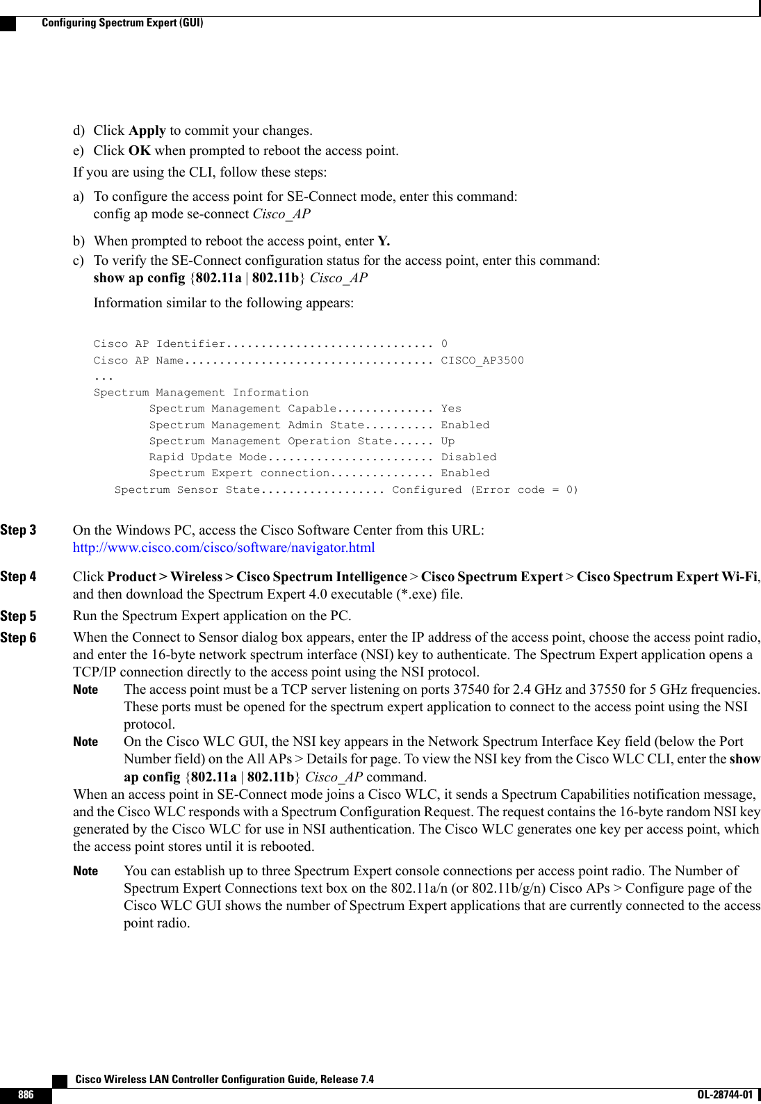
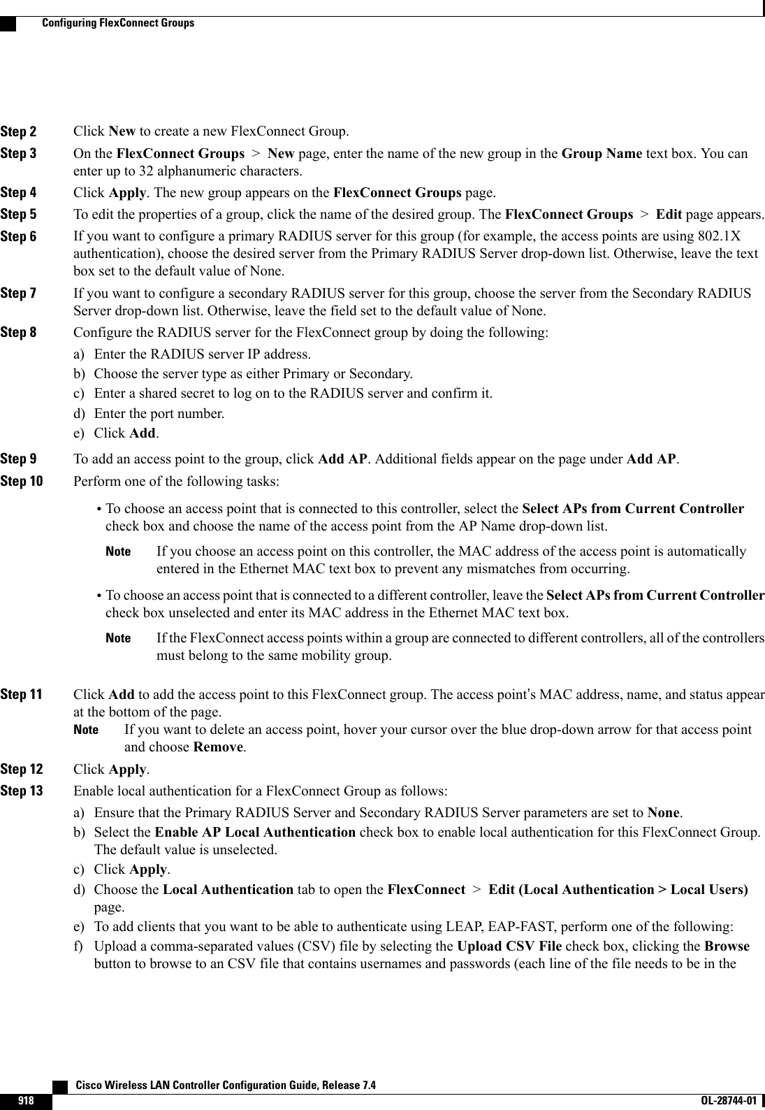
![Step 9 Click Apply to commit your changes.Step 10 Configure primary, secondary, and tertiary backup controllers for a specific access point as follows:a) Choose Access Points >All APs to open the All APs page.b) Click the name of the access point for which you want to configure primary, secondary, and tertiary backup controllers.c) Choose the High Availability tab to open the All APs > Details for (High Availability) page.d) If desired, enter the name and IP address of the primary controller for this access point in the Primary Controller textboxes.Entering an IP address for the backup controller is optional in this step and the next two steps. If the backupcontroller is outside the mobility group to which the access point is connected (the primary controller), thenyou need to provide the IP address of the primary, secondary, or tertiary controller, respectively. The controllername and IP address must belong to the same primary, secondary, or tertiary controller. Otherwise, theaccess point cannot join the backup controller.Notee) If desired, enter the name and IP address of the secondary controller for this access point in the Secondary Controllertext boxes.f) If desired, enter the name and IP address of the tertiary controller for this access point in the Tertiary Controller textboxes.g) Click Apply to commit your changes.Step 11 Click Save Configuration to save your changes.Configuring Backup Controllers (CLI)Step 1 Configure a primary controller for a specific access point by entering this command:config ap primary-base controller_name Cisco_AP [controller_ip_address]The controller_ip_address parameter in this command and the next two commands is optional. If the backupcontroller is outside the mobility group to which the access point is connected (the primary controller), thenyou need to provide the IP address of the primary, secondary, or tertiary controller, respectively. In eachcommand, the controller_name and controller_ip_address must belong to the same primary, secondary, ortertiary controller. Otherwise, the access point cannot join the backup controller.NoteStep 2 Configure a secondary controller for a specific access point by entering this command:config ap secondary-base controller_name Cisco_AP [controller_ip_address]Step 3 Configure a tertiary controller for a specific access point by entering this command:config ap tertiary-base controller_name Cisco_AP [controller_ip_address]Step 4 Configure a primary backup controller for all access points by entering this command:config advanced backup-controller primary backup_controller_name backup_controller_ip_addressStep 5 Configure a secondary backup controller for all access points by entering this command:config advanced backup-controller secondary backup_controller_name backup_controller_ip_addressTo delete a primary or secondary backup controller entry, enter 0.0.0.0 for the controller IP address.NoteStep 6 Enable or disable the fast heartbeat timer for local or FlexConnect access points by entering this command:config advanced timers ap-fast-heartbeat {local |flexconnect |all} {enable | disable}intervalCisco Wireless LAN Controller Configuration Guide, Release 7.4 OL-28744-01 761Configuring Backup Controllers (CLI)](https://usermanual.wiki/Cisco-Systems/102087P.Wireless-LAN-Controller-Configuration-Guide-Part3/User-Guide-2323189-Page-123.png)


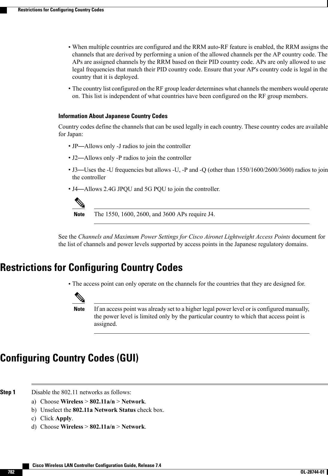
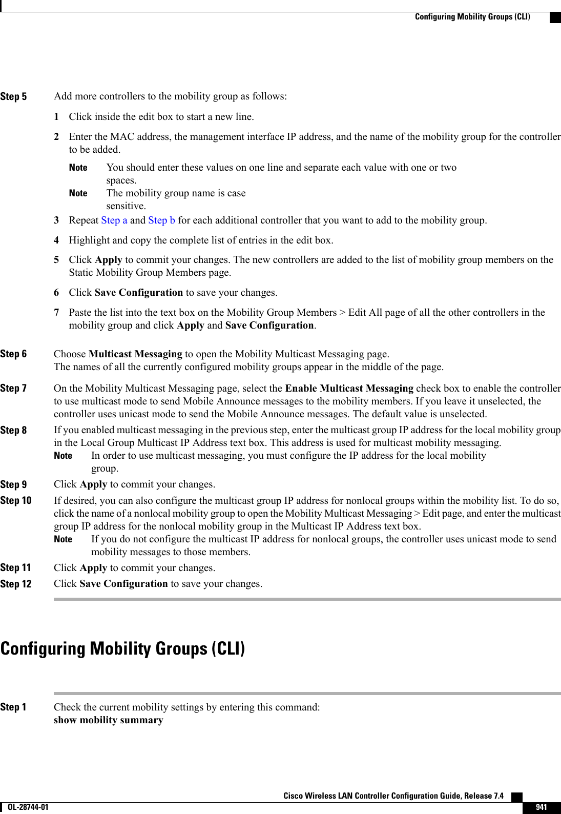
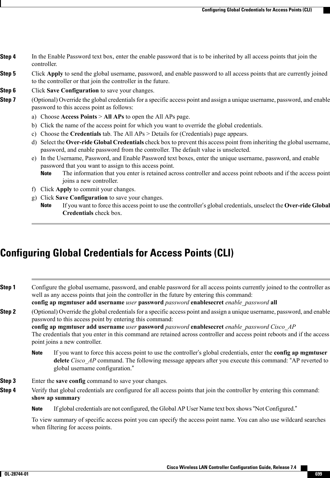
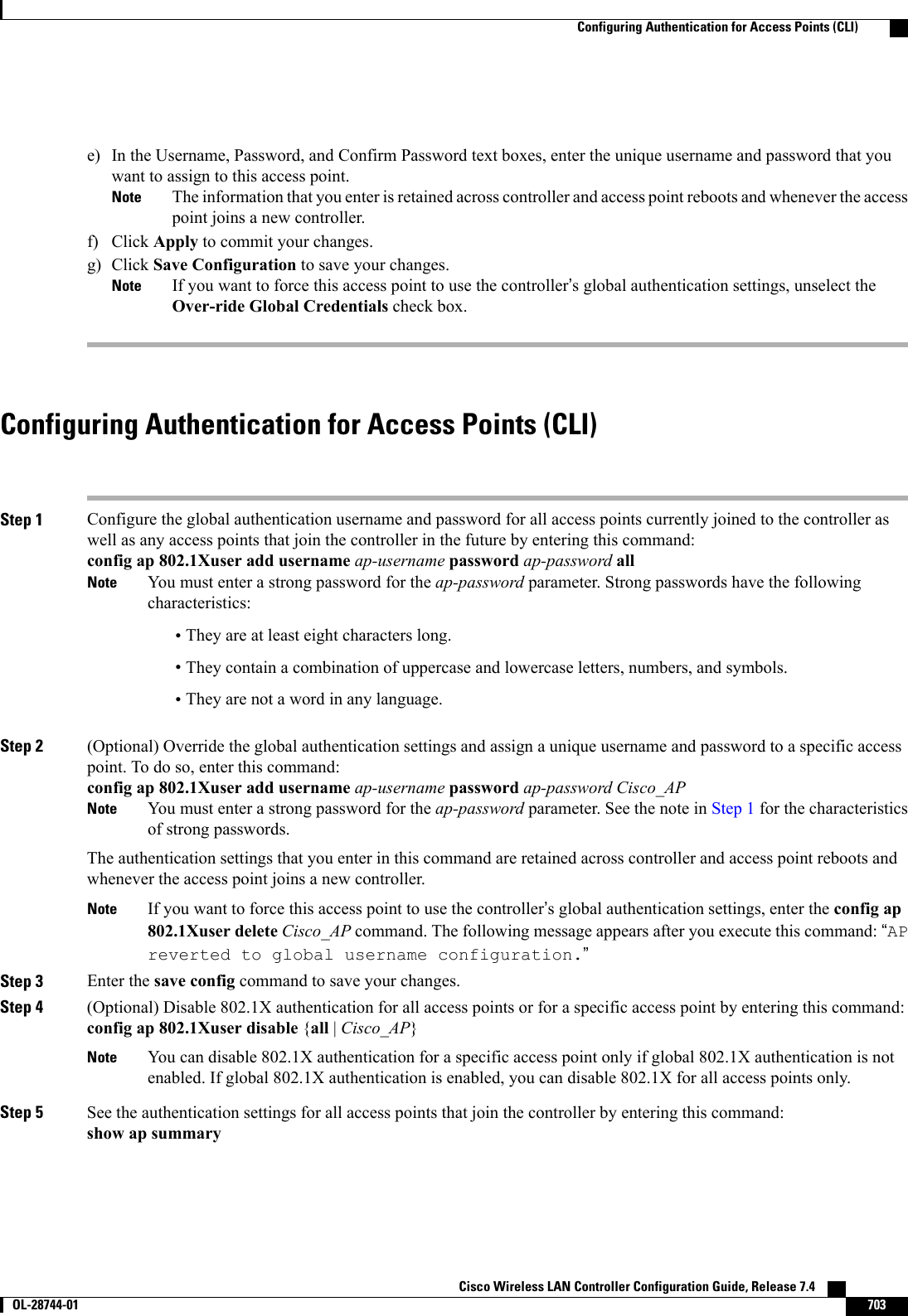
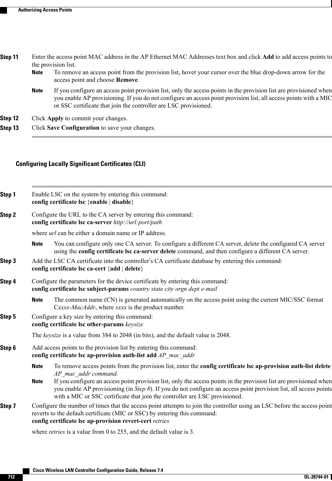
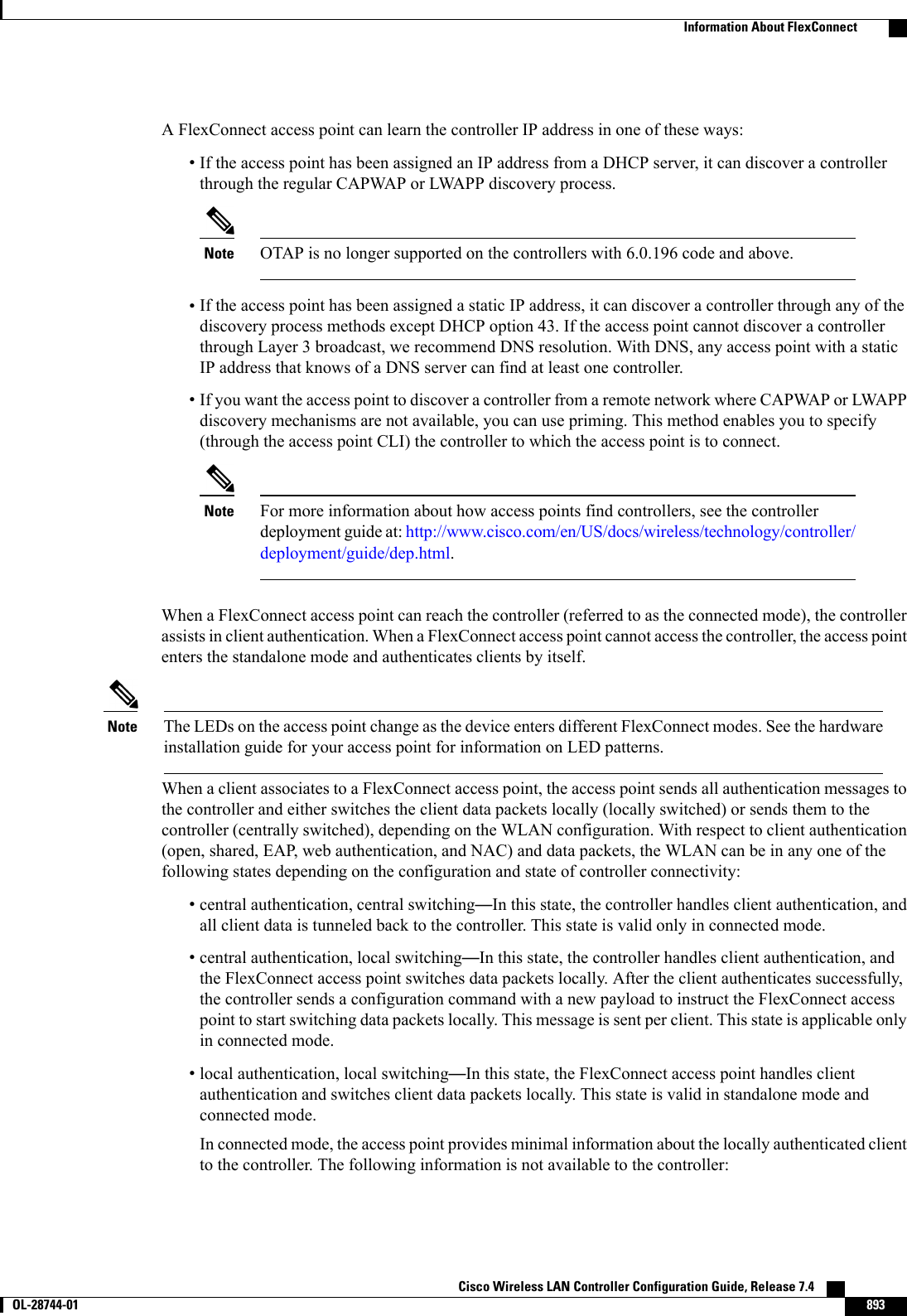
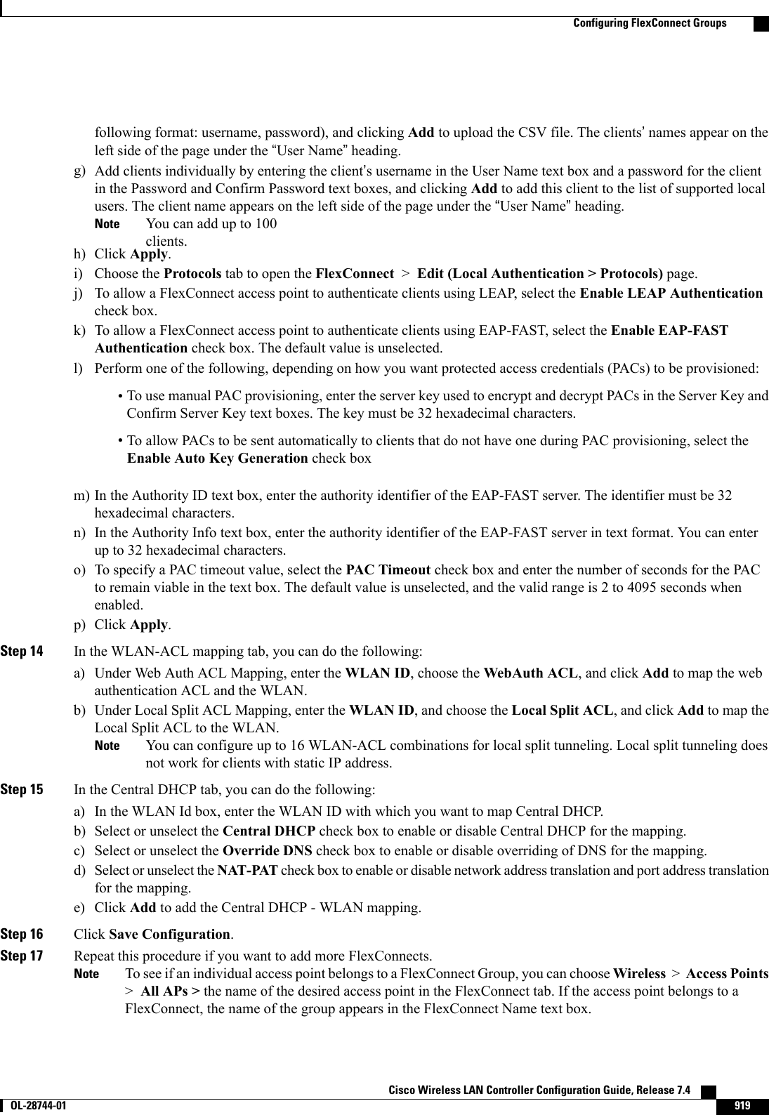
![config country code1[,code2,code3,...]If you are entering more than one country code, separate each by a comma (for example, config country US,CA,MX).Step 4 Enter Ywhen prompted to confirm your decision.Step 5 Verify your country code configuration by entering this command:show countryStep 6 See the list of available channels for the country codes configured on your controller by entering this command:show country channelsStep 7 Save your changes by entering this command:save configStep 8 See the countries to which your access points have been assigned by entering this command:To see a summary of specific access point you can specify the access point name. You can also use wildcard searcheswhen filtering for access points.show ap summaryStep 9 If you entered multiple country codes in Step 3, follow these steps to assign each access point to a specific country:a) Perform one of the following:•Leave the 802.11 networks disabled.•Reenable the 802.11 networks and then disable only the access points for which you are configuring a countrycode. To Reenable the networks, enter this command:config 802.11{a|b}enable networkTo disable an access point, enter this command:config ap disable ap_nameb) To assign an access point to a specific country, enter this command:config ap country code {ap_name |all}Make sure that the country code you choose is compatible with the regulatory domain of at least one of the accesspoint’s radios.If you enabled the networks and disabled some access points and then run the config ap country code allcommand, the specified country code is configured on only the disabled access points. All other accesspoints are ignored.Notec) To reenable any access points that you disabled in Step a, enter this command:config ap enable ap_nameStep 10 If you did not reenable the 802.11 networks in Step 9, enter these commands to reenable them now:config 802.11{a|b}enable networkStep 11 Save your changes by entering this command:save config Cisco Wireless LAN Controller Configuration Guide, Release 7.4784 OL-28744-01 Configuring Country Codes (CLI)](https://usermanual.wiki/Cisco-Systems/102087P.Wireless-LAN-Controller-Configuration-Guide-Part3/User-Guide-2323189-Page-146.png)
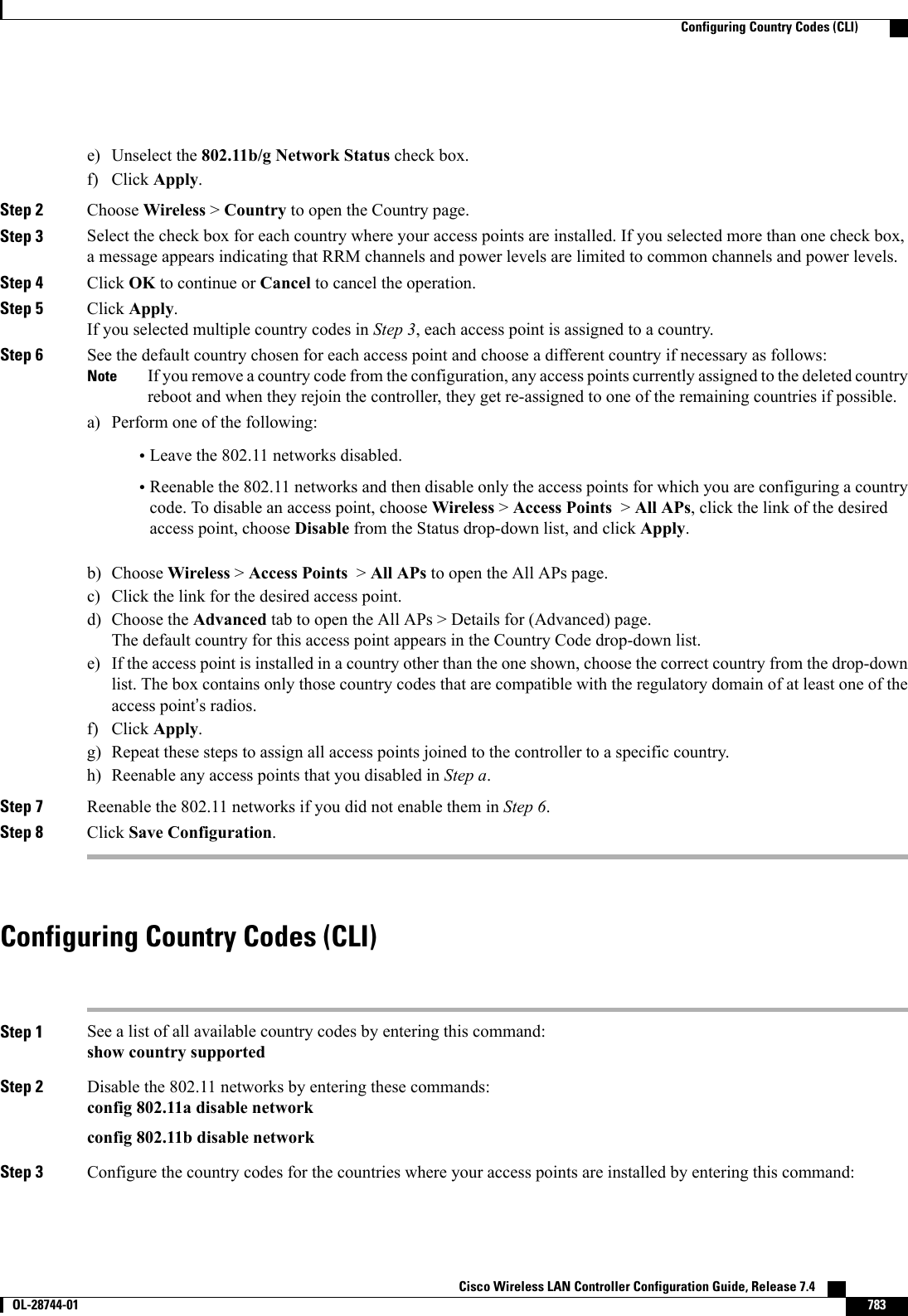
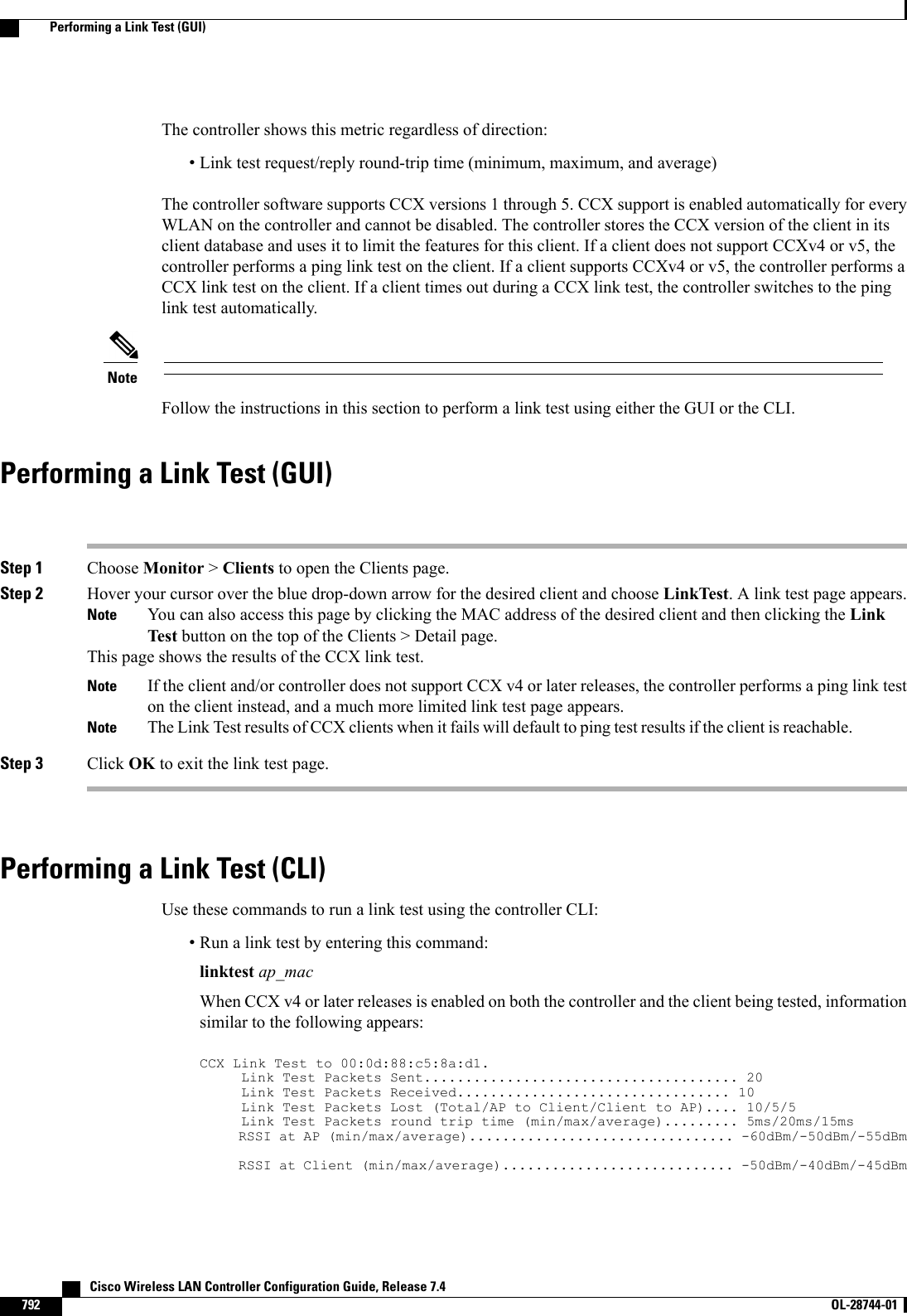
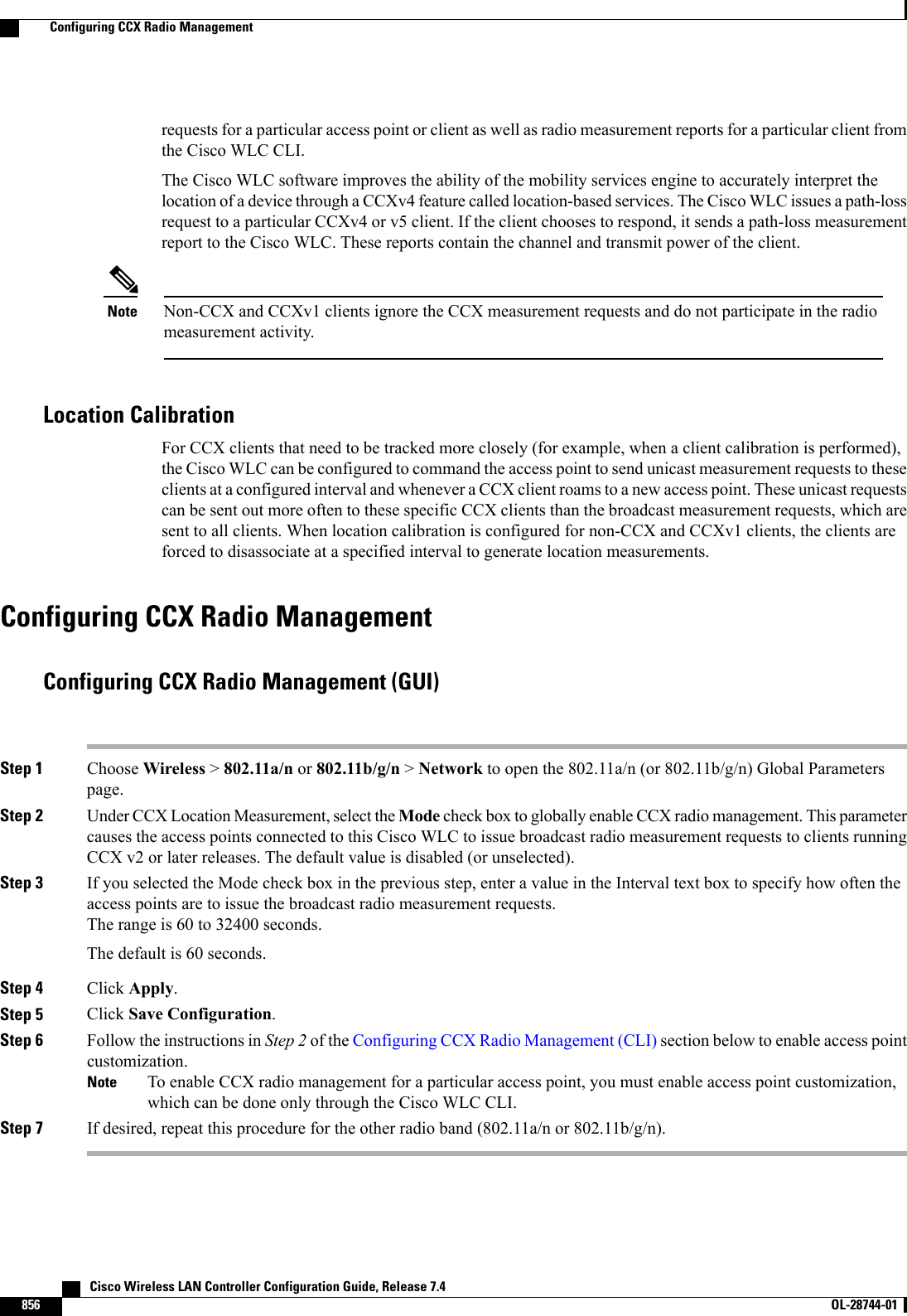
![CHAPTER 120Performing a Link Test•Information About Performing a Link Test, page 791•Performing a Link Test (GUI), page 792•Performing a Link Test (CLI), page 792Information About Performing a Link TestA link test is used to determine the quality of the radio link between two devices. Two types of link-testpackets are transmitted during a link test: request and response. Any radio receiving a link-test request packetfills in the appropriate text boxes and echoes the packet back to the sender with the response type set.The radio link quality in the client-to-access point direction can differ from that in the access point-to-clientdirection due to the asymmetrical distribution of the transmit power and receive sensitivity on both sides. Twotypes of link tests can be performed: a ping test and a CCX link test.With the ping link test, the controller can test link quality only in the client-to-access point direction. The RFparameters of the ping reply packets received by the access point are polled by the controller to determine theclient-to-access point link quality.With the CCX link test, the controller can also test the link quality in the access point-to-client direction. Thecontroller issues link-test requests to the client, and the client records the RF parameters (received signalstrength indicator [RSSI], signal-to-noise ratio [SNR], and so on). of the received request packet in the responsepacket. Both the link-test requestor and responder roles are implemented on the access point and controller.Not only can the access point or controller initiate a link test to a CCX v4 or v5 client, but a CCX v4 or v5client can initiate a link test to the access point or controller.The controller shows these link-quality metrics for CCX link tests in both directions (out—access point toclient; in—client to access point):•Signal strength in the form of RSSI (minimum, maximum, and average)•Signal quality in the form of SNR (minimum, maximum, and average)•Total number of packets that are retried•Maximum retry count for a single packet•Number of lost packets•Data rate of a successfully transmitted packetCisco Wireless LAN Controller Configuration Guide, Release 7.4 OL-28744-01 791](https://usermanual.wiki/Cisco-Systems/102087P.Wireless-LAN-Controller-Configuration-Guide-Part3/User-Guide-2323189-Page-153.png)


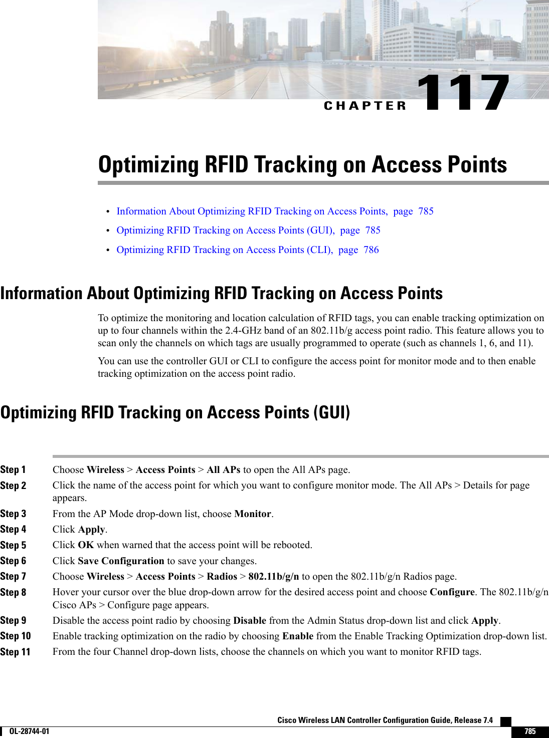
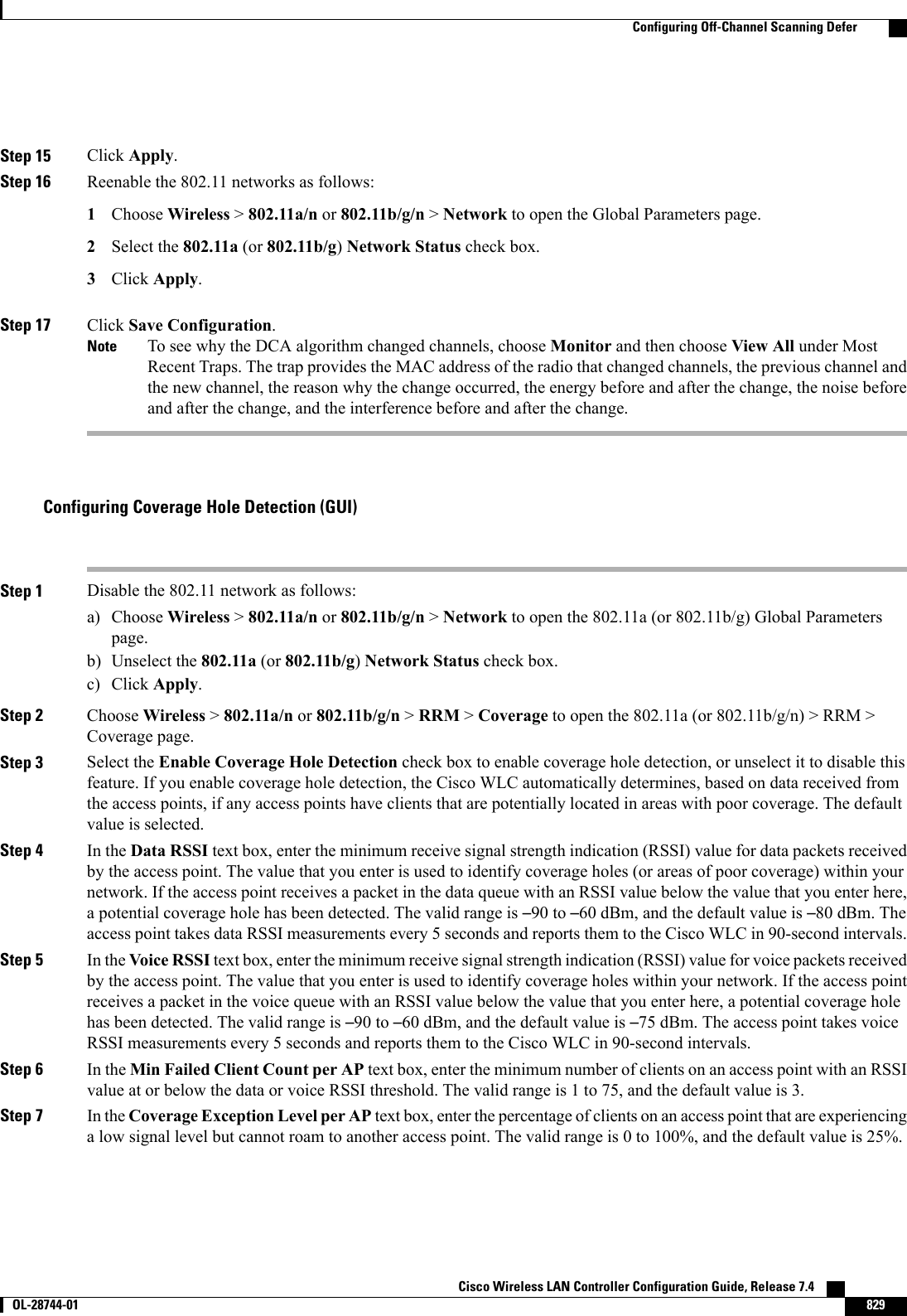
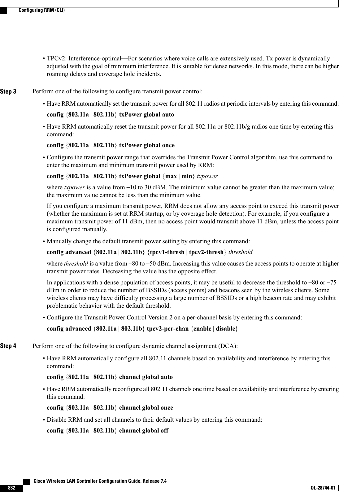
![Configuring Off Channel Scanning Defer for a WLAN (CLI)Step 1 Assign a defer-priority for the channel scan by entering this command:config wlan channel-scan defer-priority priority [enable | disable] WLAN-idThe valid range for the priority argument is 0 to 7.The priority is 0 to 7 (this value should be set to 6 on the client and on the WLAN).Use this command to configure the amount of time that scanning will be deferred following an UP packet in the queue.Step 2 Assign the channel scan defer time (in milliseconds) by entering this command:config wlan channel-scan defer-time msec WLAN-idThe time value is in miliseconds (ms) and the valid range is 100 (default) to 60000 (60 seconds). This setting shouldmatch the requirements of the equipment on your wireless LAN.You can also configure this feature on the Cisco WLC GUI by selecting WLANs, and either edit an existing WLAN orcreate a new one.Configuring Dynamic Channel Assignment (GUI)You can specify the channels that the dynamic channel assignment (DCA) algorithm considers when selectingthe channels to be used for RRM scanning by using the Cisco WLC GUI.This functionality is helpful when you know that the clients do not support certain channels because theyare legacy devices or they have certain regulatory restrictions.NoteStep 1 Disable the 802.11a/n or 802.11b/g/n network as follows:a) Choose Wireless >802.11a/n or 802.11b/g/n >Network to open the Global Parameters page.b) Unselect the 802.11a (or 802.11b/g)Network Status check box.c) Click Apply.Step 2 Choose Wireless >802.11a/n or 802.11b/g/n >RRM >DCA to open the Dynamic Channel Assignment (DCA) page.Step 3 Choose one of the following options from the Channel Assignment Method drop-down list to specify the Cisco WLC’sDCA mode:•Automatic—Causes the Cisco WLC to periodically evaluate and, if necessary, update the channel assignment forall joined access points. This is the default value.•Freeze—Causes the Cisco WLC to evaluate and update the channel assignment for all joined access points, ifnecessary, but only when you click Invoke Channel Update Once.The Cisco WLC does not evaluate and update the channel assignment immediately after you click InvokeChannel Update Once. It waits for the next interval to elapse.Note Cisco Wireless LAN Controller Configuration Guide, Release 7.4826 OL-28744-01 Configuring Off-Channel Scanning Defer](https://usermanual.wiki/Cisco-Systems/102087P.Wireless-LAN-Controller-Configuration-Guide-Part3/User-Guide-2323189-Page-188.png)


![Noise Histogram Request........................ DisabledPath Loss Request.............................. DisabledInterval....................................... 60Iteration...................................... 5B RadioBeacon Request................................. DisabledChannel Load Request........................... EnabledFrame Request.................................. DisabledNoise Histogram Request........................ EnabledPath Loss Request.............................. DisabledInterval....................................... 60Iteration................................... 5•To see the status of radio measurement requests for a particular client, enter this command:show client ccx rm client_mac statusInformation similar to the following appears:Client Mac Address............................... 00:40:96:ae:53:b4Beacon Request................................... EnabledChannel Load Request............................. DisabledFrame Request.................................... DisabledNoise Histogram Request.......................... DisabledPath Loss Request................................ DisabledInterval......................................... 5Iteration........................................ 3•To see radio measurement reports for a particular client, enter these commands:show client ccx rm client_mac report beacon—Shows the beacon report for the specified client.show client ccx rm client_mac report chan-load—Shows the channel-load report for the specifiedclient.show client ccx rm client_mac report noise-hist—Shows the noise-histogram report for the specifiedclient.show client ccx rm client_mac report frame—Shows the frame report for the specified client.•To see the clients configured for location calibration, enter this command:show client location-calibration summary•To see the RSSI reported for both antennas on each access point that heard the client, enter this command:show client detail client_macDebugging CCX Radio Management Issues (CLI)•Debug CCX broadcast measurement request activity by entering this command:debug airewave-director message {enable |disable}•Debug client location calibration activity by entering this command:debug ccxrm [all |error |warning |message |packet |detail {enable |disable}]•The CCX radio measurement report packets are encapsulated in Internet Access Point Protocol (IAPP)packets. Therefore, if the previous debug ccxrm command does not provide any debugs, enter thiscommand to provide debugs at the IAPP level:debug iapp error {enable |disable} Cisco Wireless LAN Controller Configuration Guide, Release 7.4858 OL-28744-01 Configuring CCX Radio Management](https://usermanual.wiki/Cisco-Systems/102087P.Wireless-LAN-Controller-Configuration-Guide-Part3/User-Guide-2323189-Page-220.png)

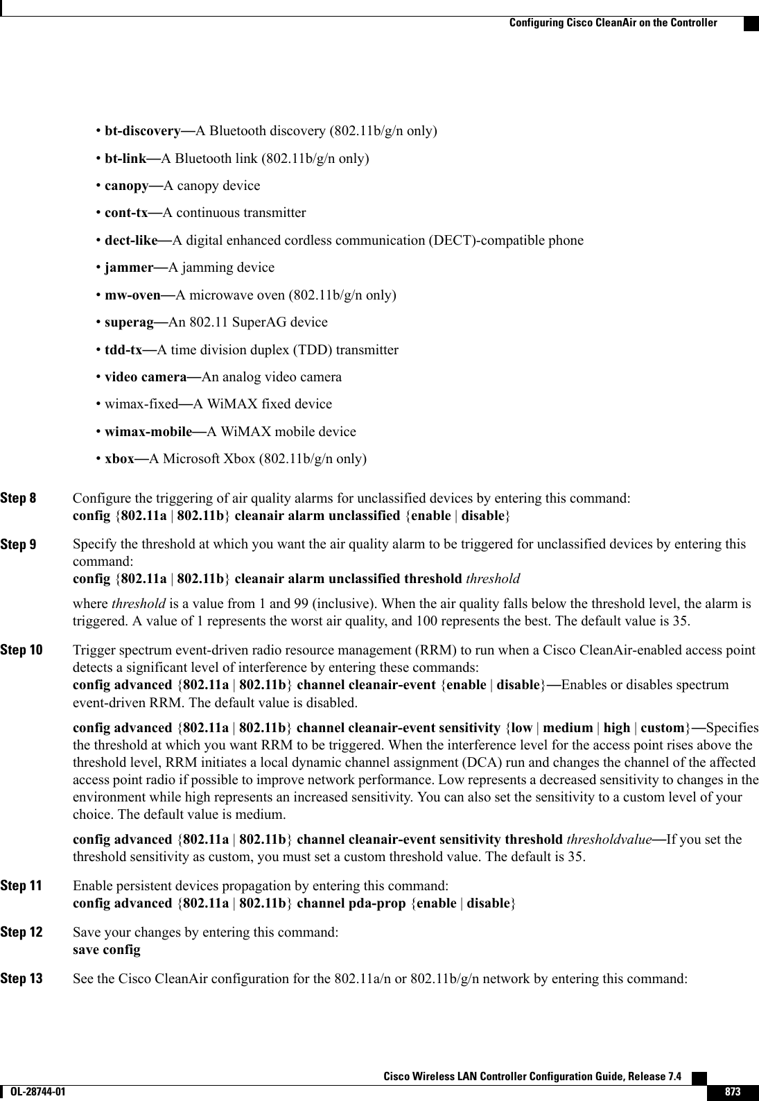
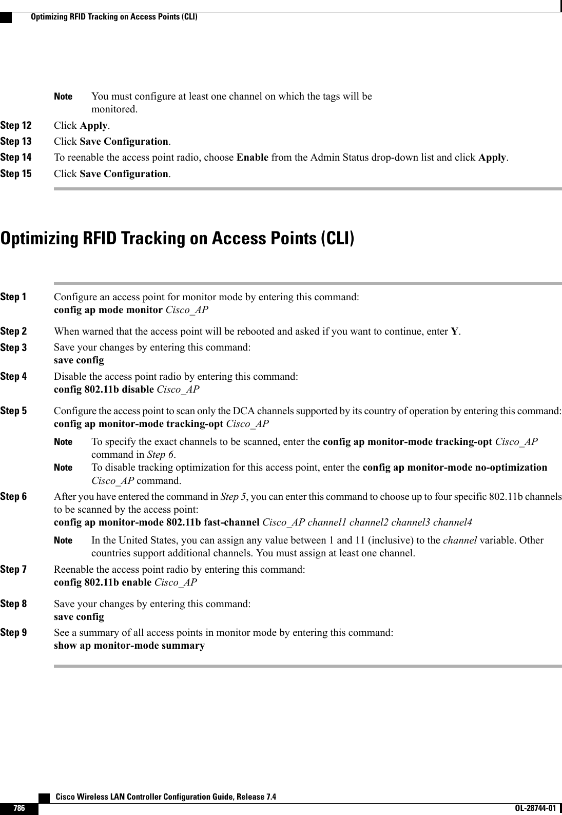
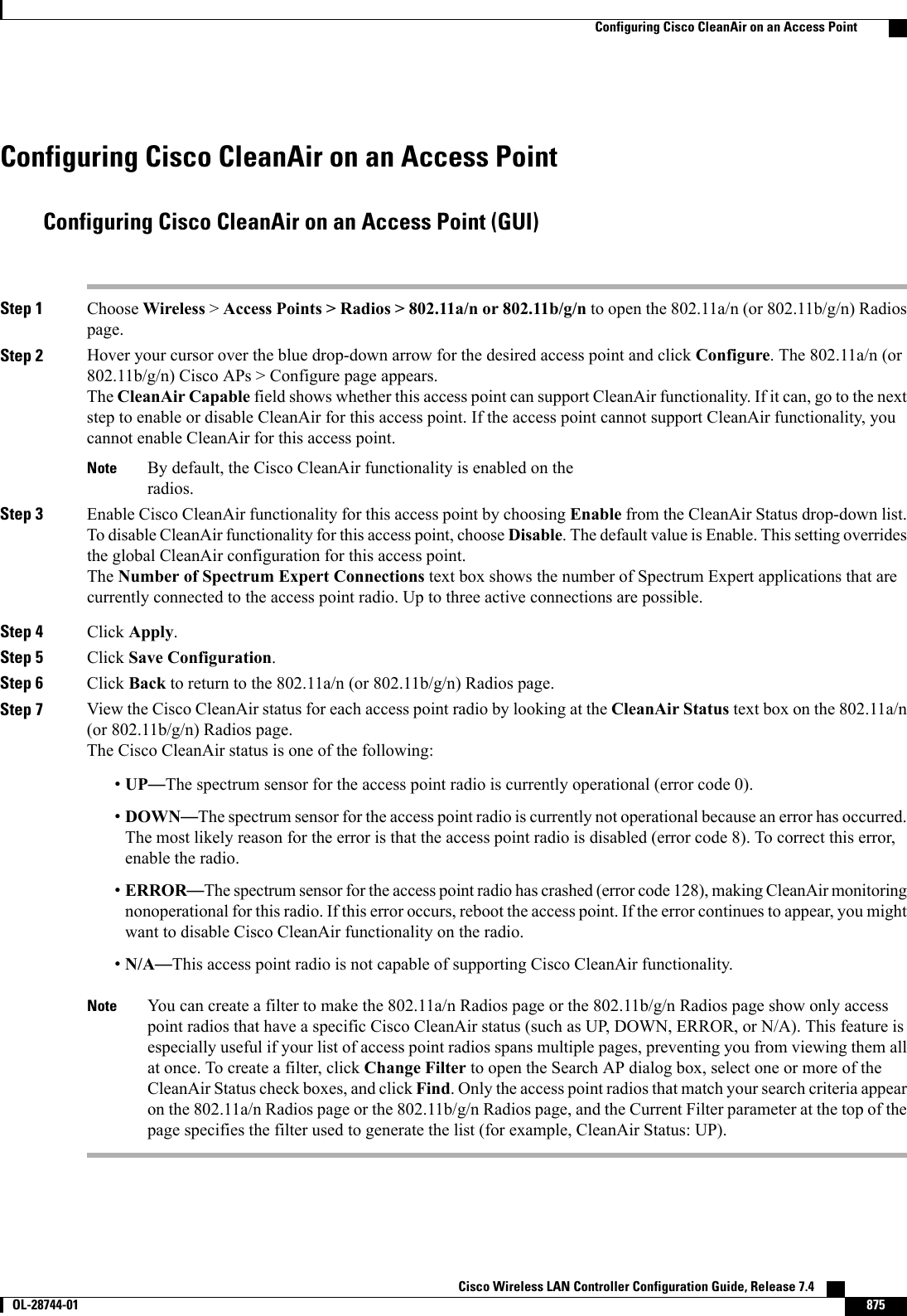
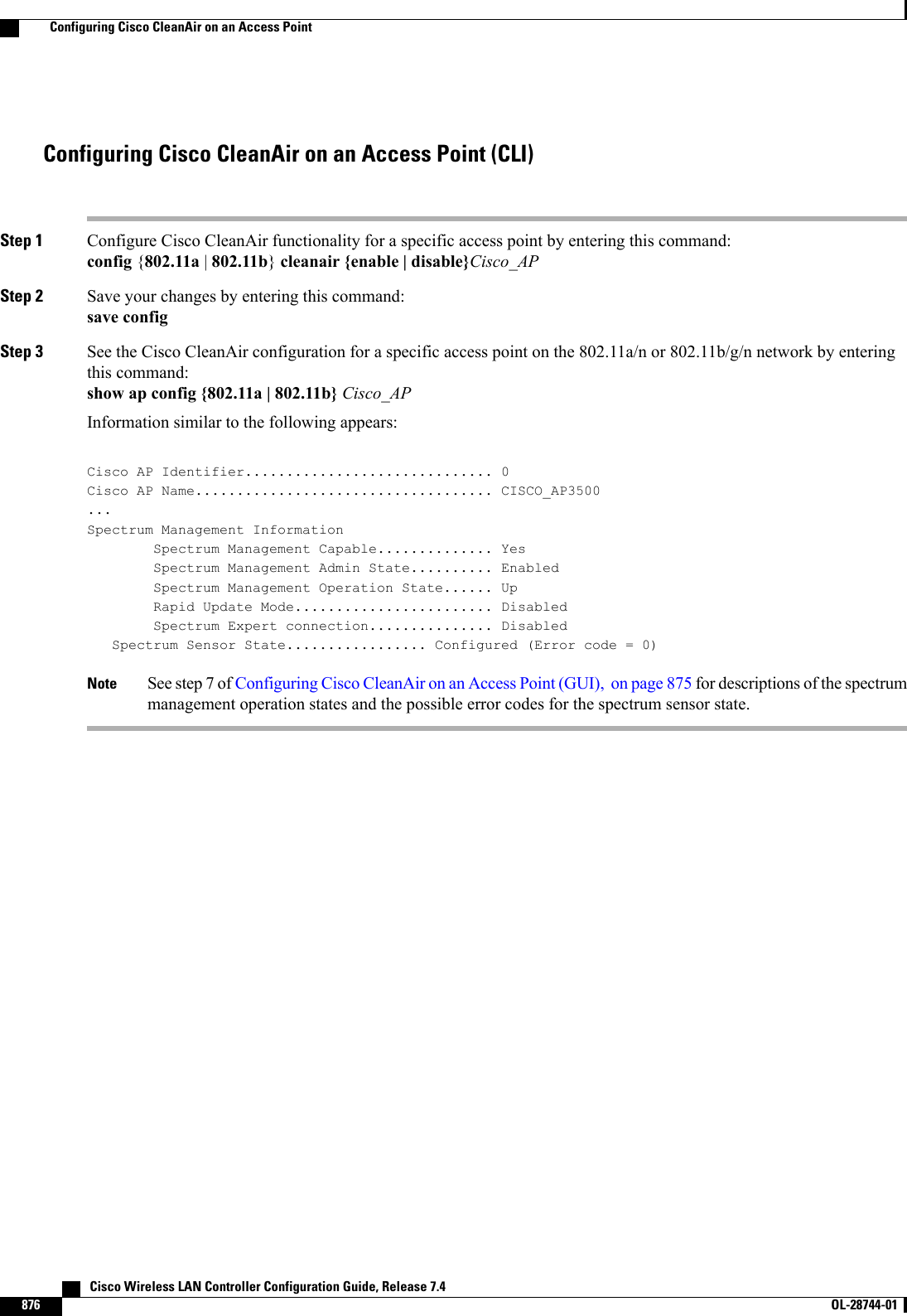
![show {802.11a |802.11b}cleanair configInformation similar to the following appears:(Cisco Controller) >show 802.11a cleanair configClean Air Solution............................... DisabledAir Quality Settings:Air Quality Reporting........................ EnabledAir Quality Reporting Period (min)........... 15Air Quality Alarms........................... EnabledAir Quality Alarm Threshold................ 35Unclassified Interference.................. DisabledUnclassified Severity Threshold............ 20Interference Device Settings:Interference Device Reporting................ EnabledInterference Device Types:TDD Transmitter.......................... EnabledJammer................................... EnabledContinuous Transmitter................... EnabledDECT-like Phone.......................... EnabledVideo Camera............................. EnabledWiFi Inverted............................ EnabledWiFi Invalid Channel..................... EnabledSuperAG.................................. EnabledCanopy................................... EnabledWiMax Mobile............................. EnabledWiMax Fixed.............................. EnabledInterference Device Alarms................... EnabledInterference Device Types Triggering Alarms:TDD Transmitter.......................... DisabledJammer................................... EnabledContinuous Transmitter................... DisabledDECT-like Phone.......................... DisabledVideo Camera............................. DisabledWiFi Inverted............................ EnabledWiFi Invalid Channel..................... EnabledSuperAG.................................. DisabledCanopy................................... DisabledWiMax Mobile............................. DisabledWiMax Fixed.............................. DisabledAdditional Clean Air Settings:CleanAir ED-RRM State........................ DisabledCleanAir ED-RRM Sensitivity.................. MediumCleanAir ED-RRM Custom Threshold............. 50CleanAir Persistent Devices state............ DisabledCleanAir Persistent Device Propagation....... EnabledStep 14 See the spectrum event-driven RRM configuration for the 802.11a/n or 802.11b/g/n network by entering this command:show advanced {802.11a |802.11b}channelInformation similar to the following appears:Automatic Channel AssignmentChannel Assignment Mode........................ AUTOChannel Update Interval........................ 600 seconds [startup]Anchor time (Hour of the day).................. 0Channel Update Contribution.................... SNICleanAir Event-driven RRM option.............. EnabledCleanAir Event-driven RRM sensitivity...... Medium Cisco Wireless LAN Controller Configuration Guide, Release 7.4874 OL-28744-01 Configuring Cisco CleanAir on the Controller](https://usermanual.wiki/Cisco-Systems/102087P.Wireless-LAN-Controller-Configuration-Guide-Part3/User-Guide-2323189-Page-236.png)


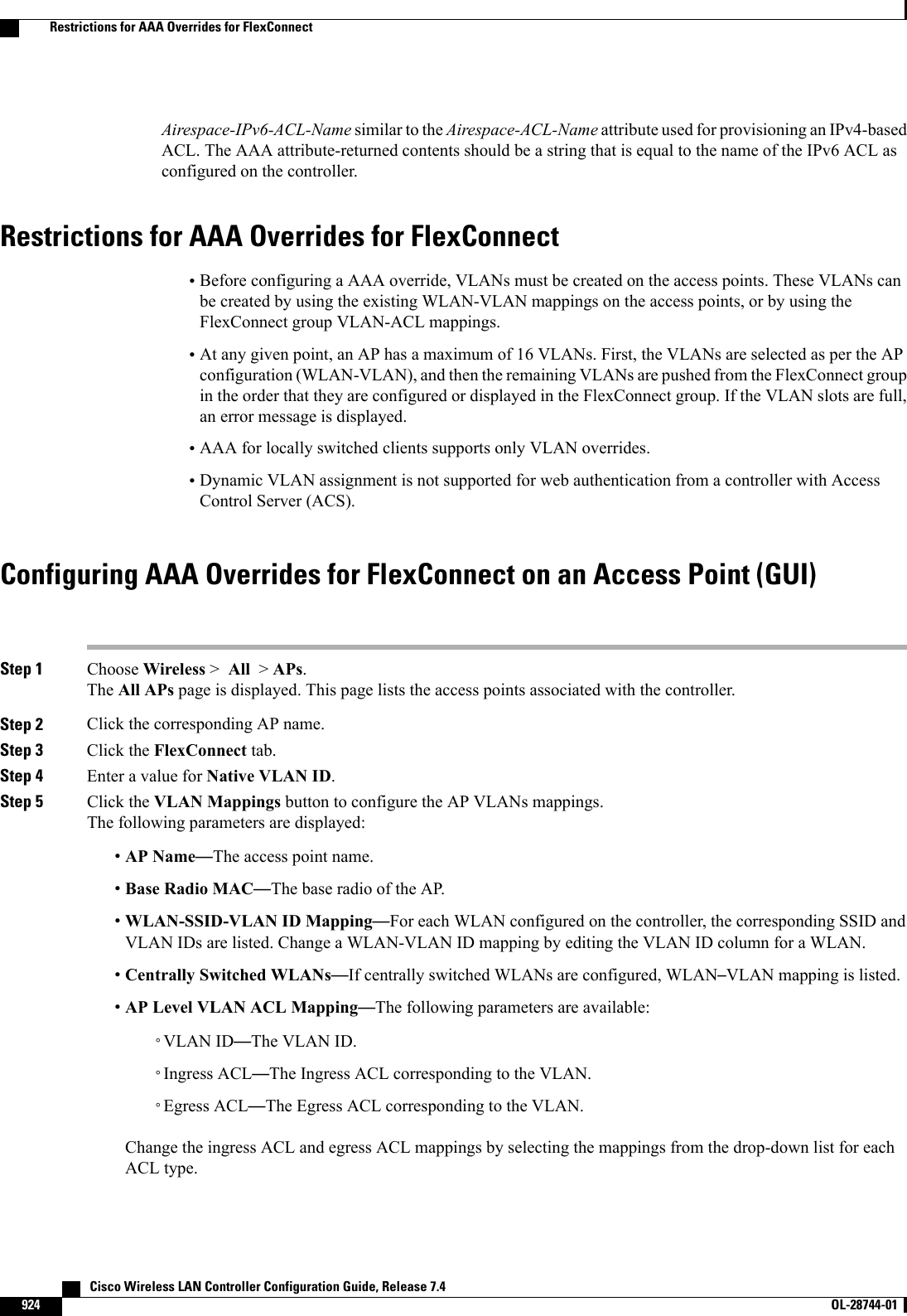
![CHAPTER 140Configuring AAA Overrides for FlexConnect•Information About Authentication, Authorization, Accounting Overrides, page 923•Restrictions for AAA Overrides for FlexConnect, page 924•Configuring AAA Overrides for FlexConnect on an Access Point (GUI), page 924•Configuring VLAN Overrides for FlexConnect on an Access Point (CLI), page 925Information About Authentication, Authorization, Accounting OverridesThe Allow Authentication, Authorization, Accouting (AAA) Override option of a WLAN enables you toconfigure the WLAN for authentication. It enables you to apply VLAN tagging, QoS, and ACLs to individualclients based on the returned RADIUS attributes from the AAA server.AAA overrides for FlexConnect access points introduce a dynamic VLAN assignment for locally switchedclients. AAA overrides for FlexConnect also support fast roaming (Opportunistic Key Caching [OKC]/ CiscoCentralized Key management [CCKM]) of overridden clients.VLAN overrides for FlexConnect are applicable for both centrally and locally authenticated clients. VLANscan be configured on FlexConnect groups.If a VLAN on the AP is configured using the WLAN-VLAN, the AP configuration of the corresponding ACLis applied. If the VLAN is configured using the FlexConnect group, the corresponding ACL configured onthe FlexConnect group is applied. If the same VLAN is configured on the FlexConnect group and also on theAP, the AP configuration, with its ACL takes precedence. If there is no slot for a new VLAN from theWLAN-VLAN mapping, the latest configured FlexConnect group VLAN is replaced.If the VLAN that was returned from the AAA is not present on the AP, the client falls back to the defaultVLAN configured for the WLAN.Before configuring a AAA override, the VLAN must be created on the access points. These VLANs can becreated by using the existing WLAN-VLAN mappings on the access points, or by using the FlexConnectgroup VLAN-ACL mappings.AAA Override for IPv6 ACLsIn order to support centralized access control through a centralized AAA server such as the Cisco IdentityServices Engine (ISE) or ACS, the IPv6 ACL can be provisioned on a per-client basis using AAA Overrideattributes. In order to use this feature, the IPv6 ACL must be configured on the controller and the WLANmust be configured with the AAA Override feature enabled. The AAA attribute for an IPv6 ACL isCisco Wireless LAN Controller Configuration Guide, Release 7.4 OL-28744-01 923](https://usermanual.wiki/Cisco-Systems/102087P.Wireless-LAN-Controller-Configuration-Guide-Part3/User-Guide-2323189-Page-285.png)