City Theatrical 5691 SHOW DMX TRANSCEIVER User Manual SHoW DMX Manual R1 0

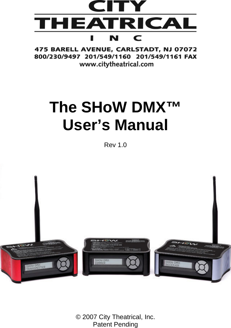
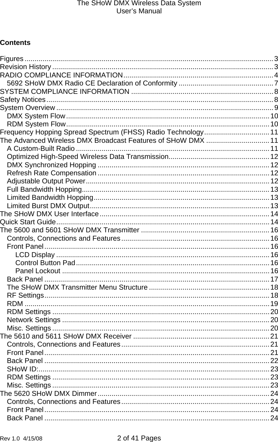
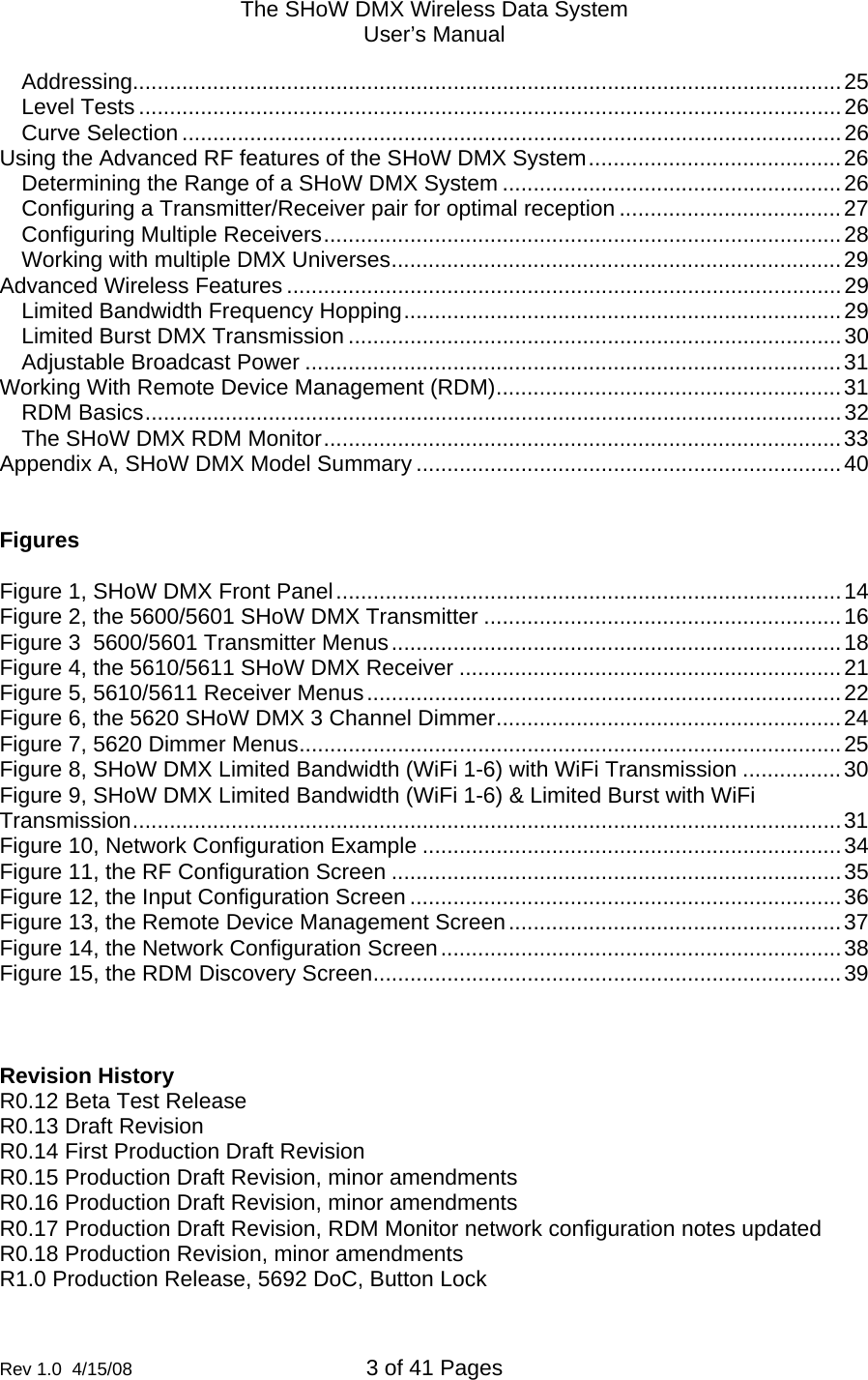
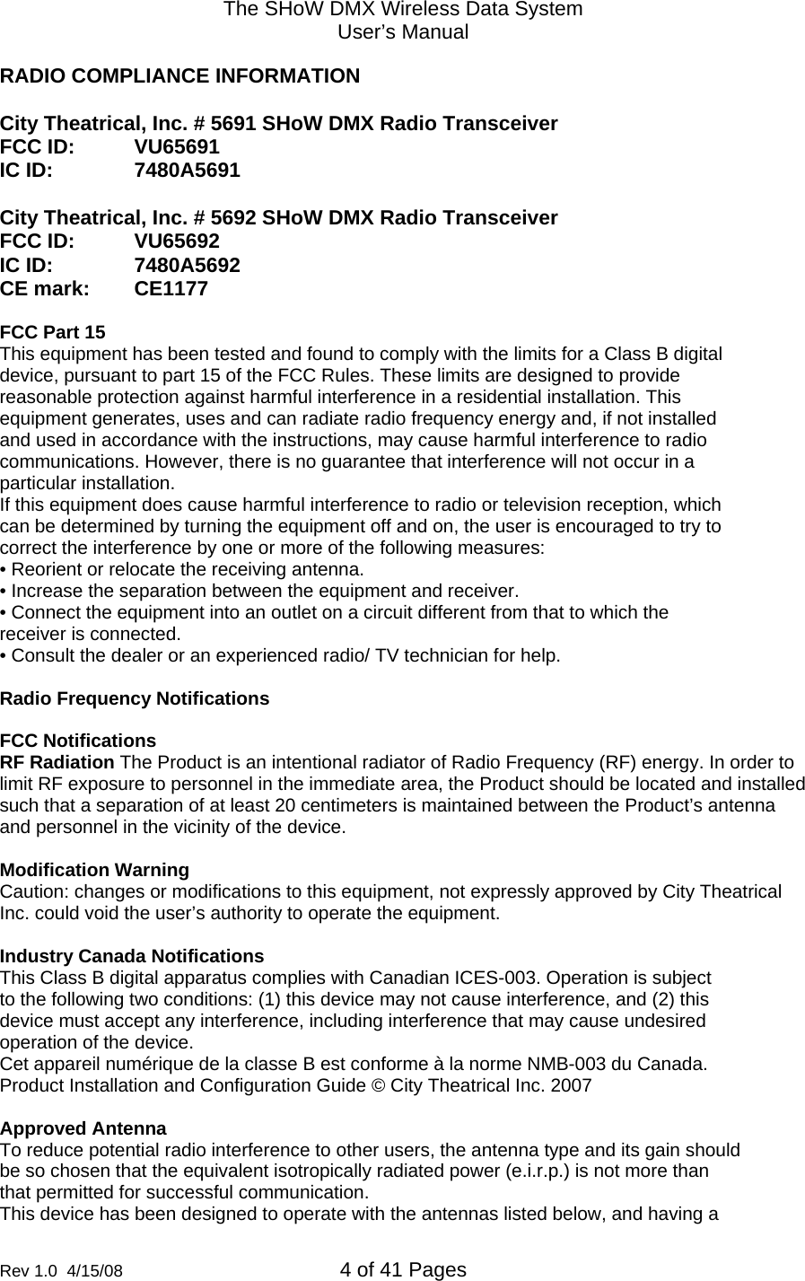
CITY THEATRICAL, INC. SHOW DMX TRANSCEIVER SHoW DMX Manual R1 0

User Manual

       The SHoW DMX™ User’s Manual  Rev 1.0      © 2007 City Theatrical, Inc. Patent Pending
The SHoW DMX Wireless Data System User’s Manual  Rev 1.0  4/15/08  2 of 41 Pages          Contents  Figures ..............................................................................................................................3 Revision History ................................................................................................................3 RADIO COMPLIANCE INFORMATION............................................................................4 5692 SHoW DMX Radio CE Declaration of Conformity ................................................7 SYSTEM COMPLIANCE INFORMATION ........................................................................8 Safety Notices...................................................................................................................8 System Overview ..............................................................................................................9 DMX System Flow.......................................................................................................10 RDM System Flow.......................................................................................................10 Frequency Hopping Spread Spectrum (FHSS) Radio Technology.................................11 The Advanced Wireless DMX Broadcast Features of SHoW DMX ................................11 A Custom-Built Radio ..................................................................................................11 Optimized High-Speed Wireless Data Transmission...................................................12 DMX Synchronized Hopping .......................................................................................12 Refresh Rate Compensation .......................................................................................12 Adjustable Output Power.............................................................................................12 Full Bandwidth Hopping...............................................................................................13 Limited Bandwidth Hopping.........................................................................................13 Limited Burst DMX Output...........................................................................................13 The SHoW DMX User Interface......................................................................................14 Quick Start Guide............................................................................................................14 The 5600 and 5601 SHoW DMX Transmitter .................................................................16 Controls, Connections and Features...........................................................................16 Front Panel..................................................................................................................16 LCD Display ............................................................................................................16 Control Button Pad..................................................................................................16 Panel Lockout .........................................................................................................16 Back Panel ..................................................................................................................17 The SHoW DMX Transmitter Menu Structure .............................................................18 RF Settings..................................................................................................................18 RDM ............................................................................................................................19 RDM Settings ..............................................................................................................20 Network Settings .........................................................................................................20 Misc. Settings ..............................................................................................................20 The 5610 and 5611 SHoW DMX Receiver .....................................................................21 Controls, Connections and Features...........................................................................21 Front Panel..................................................................................................................21 Back Panel ..................................................................................................................22 SHoW ID:.....................................................................................................................23 RDM Settings ..............................................................................................................23 Misc. Settings ..............................................................................................................23 The 5620 SHoW DMX Dimmer.......................................................................................24 Controls, Connections and Features...........................................................................24 Front Panel..................................................................................................................24 Back Panel ..................................................................................................................24
The SHoW DMX Wireless Data System User’s Manual  Rev 1.0  4/15/08  3 of 41 Pages        Addressing...................................................................................................................25 Level Tests ..................................................................................................................26 Curve Selection ...........................................................................................................26 Using the Advanced RF features of the SHoW DMX System.........................................26 Determining the Range of a SHoW DMX System .......................................................26 Configuring a Transmitter/Receiver pair for optimal reception ....................................27 Configuring Multiple Receivers....................................................................................28 Working with multiple DMX Universes.........................................................................29 Advanced Wireless Features ..........................................................................................29 Limited Bandwidth Frequency Hopping.......................................................................29 Limited Burst DMX Transmission ................................................................................30 Adjustable Broadcast Power .......................................................................................31 Working With Remote Device Management (RDM)........................................................31 RDM Basics.................................................................................................................32 The SHoW DMX RDM Monitor....................................................................................33 Appendix A, SHoW DMX Model Summary .....................................................................40   Figures  Figure 1, SHoW DMX Front Panel..................................................................................14 Figure 2, the 5600/5601 SHoW DMX Transmitter ..........................................................16 Figure 3  5600/5601 Transmitter Menus.........................................................................18 Figure 4, the 5610/5611 SHoW DMX Receiver ..............................................................21 Figure 5, 5610/5611 Receiver Menus.............................................................................22 Figure 6, the 5620 SHoW DMX 3 Channel Dimmer........................................................24 Figure 7, 5620 Dimmer Menus........................................................................................25 Figure 8, SHoW DMX Limited Bandwidth (WiFi 1-6) with WiFi Transmission ................30 Figure 9, SHoW DMX Limited Bandwidth (WiFi 1-6) & Limited Burst with WiFi Transmission...................................................................................................................31 Figure 10, Network Configuration Example ....................................................................34 Figure 11, the RF Configuration Screen .........................................................................35 Figure 12, the Input Configuration Screen ......................................................................36 Figure 13, the Remote Device Management Screen......................................................37 Figure 14, the Network Configuration Screen.................................................................38 Figure 15, the RDM Discovery Screen............................................................................39    Revision History R0.12 Beta Test Release R0.13 Draft Revision R0.14 First Production Draft Revision R0.15 Production Draft Revision, minor amendments R0.16 Production Draft Revision, minor amendments R0.17 Production Draft Revision, RDM Monitor network configuration notes updated R0.18 Production Revision, minor amendments R1.0 Production Release, 5692 DoC, Button Lock
The SHoW DMX Wireless Data System User’s Manual  Rev 1.0  4/15/08  4 of 41 Pages        RADIO COMPLIANCE INFORMATION  City Theatrical, Inc. # 5691 SHoW DMX Radio Transceiver FCC ID:  VU65691 IC ID:    7480A5691  City Theatrical, Inc. # 5692 SHoW DMX Radio Transceiver FCC ID:  VU65692 IC ID:    7480A5692 CE mark:  CE1177     FCC Part 15 This equipment has been tested and found to comply with the limits for a Class B digital device, pursuant to part 15 of the FCC Rules. These limits are designed to provide reasonable protection against harmful interference in a residential installation. This equipment generates, uses and can radiate radio frequency energy and, if not installed and used in accordance with the instructions, may cause harmful interference to radio communications. However, there is no guarantee that interference will not occur in a particular installation. If this equipment does cause harmful interference to radio or television reception, which can be determined by turning the equipment off and on, the user is encouraged to try to correct the interference by one or more of the following measures: • Reorient or relocate the receiving antenna. • Increase the separation between the equipment and receiver. • Connect the equipment into an outlet on a circuit different from that to which the receiver is connected. • Consult the dealer or an experienced radio/ TV technician for help.  Radio Frequency Notifications  FCC Notifications RF Radiation The Product is an intentional radiator of Radio Frequency (RF) energy. In order to limit RF exposure to personnel in the immediate area, the Product should be located and installed such that a separation of at least 20 centimeters is maintained between the Product’s antenna and personnel in the vicinity of the device.  Modification Warning Caution: changes or modifications to this equipment, not expressly approved by City Theatrical Inc. could void the user’s authority to operate the equipment.  Industry Canada Notifications This Class B digital apparatus complies with Canadian ICES-003. Operation is subject to the following two conditions: (1) this device may not cause interference, and (2) this device must accept any interference, including interference that may cause undesired operation of the device. Cet appareil numérique de la classe B est conforme à la norme NMB-003 du Canada. Product Installation and Configuration Guide © City Theatrical Inc. 2007  Approved Antenna To reduce potential radio interference to other users, the antenna type and its gain should be so chosen that the equivalent isotropically radiated power (e.i.r.p.) is not more than that permitted for successful communication. This device has been designed to operate with the antennas listed below, and having a
The SHoW DMX Wireless Data System User’s Manual  Rev 1.0  4/15/08  5 of 41 Pages        maximum gain of 14dBi. Antennas not included in this list or having a gain greater than 14dBiare strictly prohibited for use with this device. The required antenna impedance is 50 ohms.       Approved Antennas:   Manufacturer  Model  Type  Connector  Gain 1  Nearson  S151AH-2450S  Omni whip  SMA plug reverse polarity  5dBi 2  Nearson  S141AH-2450  Omni whip  SMA plug reverse polarity  2dBi 3  Centurion  WCP2400-MMCX4  Omni whip  MMCX jack on 4'' coax pigtail 2.5dBi 4  Maxrad  MP24008XFPT  Panel  MMCX jack on 4'' coax pigtail / SMA plug reverse polarity 8.5dBi 5  Maxrad  MP24012CPLXFPT  Panel  MMCX jack on 4'' coax pigtail / SMA plug reverse polarity 12.0dBic 6  Maxrad  MYP24010PT  Yagi  MMCX jack on 4'' coax pigtail / SMA plug reverse polarity 10dBi 7  Maxrad  MYP24014PT  Yagi  MMCX jack on 4'' coax pigtail / SMA plug reverse polarity 14dBi
The SHoW DMX Wireless Data System User’s Manual  Rev 1.0  4/15/08  6 of 41 Pages                le départment. L'utilisation en extérieur est soumis à autorisation préalable et très restreint. Vous pouvez contacter l'Autorité de Régulation des Télécommunications (http://www.art-telecom.fr) pour de plus amples renseignements.    CE Mark Conformity City Theatrical Inc. declares that this product conforms to the specifications listed in this manual, following the provisions of the European R&TTE directive 1999/5/EC: City Theatrical Inc. vakuuttaa täten että dieses produkt tyyppinen laite on direktiivin 1999/5/EY oleellisten vaatimusten ja sitä koskevien näiden direktiivien muiden ehtojen mukainen. City Theatrical Inc. déclare que le produit est conforme aux conditions essentielles et aux dispositions relatives à la directive 1999/5/EC. • EN 301 489-1, 301 489-17 General EMC requirements for Radio equipment. • EN 60950 Safety • EN 300 328 Technical requirements for Radio equipment. CAUTION—This equipment is intended to be used in all EU and EFTA countries. Outdoor use may be restricted to certain frequencies and/or may require a license for operation. Contact local Authority for procedure to follow. Note: ESD precautions should be used when attaching or removing the antenna. Note: Combinations of power levels and antennas resulting in a radiated power level of above 100 mW equivalent isotropic radiated power (EIRP) are considered as not compliant with the above mentioned directive and are not allowed for use within the European community and countries that have adopted the European R&TTE directive 1999/5/EC. For more details on legal combinations of power levels and antennas, contact City Theatrical Inc. Do not use this product near water, for example, in a wet basement or near a swimming pool. Avoid using this product during an electrical storm. There may be a remote risk of electric shock from lightning. 72 Product Installation and Configuration Guide © City Theatrical Inc. 2007  Q52 Regulatory information Radio Frequency Notifications Belgique Dans le cas d'une utilisation privée, à l'extérieur d'un bâtiment, au-dessus d'un espace public, aucun enregistrement n'est nécessaire pour une distance de moins de 300m. Pour une distance supérieure à 300m un enregistrement auprès de l'IBPT est requise. Pour une utilisation publique à l'extérieur de bâtiments, une licence de l'IBPT est requise. Pour les enregistrements et licences, veuillez contacter l'IBPT. France 2.4 GHz Bande : les canaux 10, 11, 12, 13 (2457, 2462, 2467, et 2472 MHz respectivement) sont complétement libres d'utilisation en France (en utilisation intérieur). Pour ce qui est des autres canaux, ils peuvent être soumis à autorisation selon
The SHoW DMX Wireless Data System User’s Manual  Rev 1.0  4/15/08  7 of 41 Pages        5692 SHoW DMX Radio CE Declaration of Conformity
The SHoW DMX Wireless Data System User’s Manual  Rev 1.0  4/15/08  8 of 41 Pages        SYSTEM COMPLIANCE INFORMATION  The 5610 and 5611 Receiver and 5620 Dimmer are ETL and cETL Listed as follows: •  ETL Listed, Conforms to UL 508A •  cETL Listed, Certified to Can/CSA Standard 22.2 14-95  The 5601 Transmitter, the 5611 Receiver, and the 5620 Dimmer are CE Certified Standards Applied:  BS EN 60950-1:2002 incorporating Corrigendum No. 1 and Amendment No. 1 EN 55203-1: 1996 EN 55203-2: 1996 EN 301 489-1 V1.4.1 EN 301 489-3 V1.4.1  Products Conform to CE Marking Directive 93/68/EEC All SHoW DMX models are RoHS compliant Safety Notices Please read this entire manual before using your new equipment.  Please keep the manual in a safe place so you can refer to it in the future as required.  The SHoW DMX System is intended for use only by qualified professionals.  Connection, installation and hanging of this equipment must be performed in accordance with all pertinent local, regional and national safety codes and regulations.    SHoW DMX equipment is intended for indoor use only unless specified for outdoor use.  Keep the equipment dry!  Do not operate the equipment if it gets wet!  Do not operate in excessive heat/direct sunlight.  Be sure installation provides adequate ventilation.  Some system components can produce significant heat and must be properly installed to allow proper cooling and assure user safety (please see specific notes about 5620 Dimmer installation and heat in this manual).   All sides of the equipment must be clear of obstruction and allow free airflow.  There are no user-serviceable parts inside!  Refer to qualified service personnel! RF Exposure:  The antenna(s) used for this transmitter must be installed to provide a separation distance of at least 20cm from all persons and must not be  collocated or operating in conjunction with any other antenna or transmitter.
The SHoW DMX Wireless Data System User’s Manual  Rev 1.0  4/15/08  9 of 41 Pages        Introduction Thank you for selecting City Theatrical’s SHoW DMX System! The SHoW DMX System is an advanced 2.4Ghz Frequency Hopping Spread Spectrum (FHSS) wireless DMX and RDM distribution and low voltage lighting control system.  SHoW DMX is intended to provide superior broadcast reliability and fidelity while offering a range of power and frequency hopping configurations designed to enhance system compatibility with other types of 2.4Ghz systems that may be negatively affected by conventional 2.4Ghz FHSS systems.    In other words, SHoW DMX is meant to be a powerful and high fidelity but “low impact” wireless system with the best features of FHSS.  Many of these “low impact” and improved fidelity features are patent pending.  The SHoW DMX System incorporates a number of new broadcast features to enhance radio data delivery and fidelity, including high speed broadcast data rate with optimized data format, DMX synchronized hopping, adjustable output power, full bandwidth hopping, and limited bandwidth hopping.  Each of these features is discussed in detail in this manual.    Every effort has been made to anticipate your questions in this manual, but if you have any questions that are not answered here, or you want to discuss a special application, please feel free to contact us directly at City Theatrical.  The SHoW DMX System includes a wide range of products which you may review at our website (www.citytheatrical.com) or in our catalog.  For basic wireless operation, a minimum of one SHoW DMX Transmitter and one SHoW DMX Receiver is required.  SHoW DMX 3 Channel Dimmers are fully RDM/DMX compliant wired devices and may also be used in conventional wired DMX or RDM/DMX systems.  System Overview The SHoW DMX System is a complete wireless DMX/RDM lighting system, intended to provide everything needed for general wireless DMX/RDM distribution, wireless control and battery powered operation of lighting and stage effects, including costume and set lighting and effects control, or any other application where wireless DMX/RDM control and/or battery powered dimming or effects control might be needed.  In addition to the powerful but gentle wireless DMX/RDM distribution that SHoW DMX provides, the SHoW DMX Three Channel 10A Dimmer serves as a versatile lighting control module, providing three channels of 9-24VDC incandescent ISL and Linear dimming, Non Dim control, and RGB LED control in a single feature-packed unit.  The SHoW DMX System includes the 5600 and 5601 Transmitters, the 5610 and 5611 Receivers, and the 5620 Three Channel 10A Dimmer.  The 5600 Transmitter and 5610 Receiver are designed for use in North America.  The 5601 Transmitter, 5611 Receiver and 5620 Three Channel 10A Dimmer are certified for use in North America and also are CE certified for use in Europe.  Setting up a SHoW DMX system is quite similar to setting up any DMX512 control system.  The principal thing to remember is that the Transmitter and Receiver(s) replace DMX cable.
The SHoW DMX Wireless Data System User’s Manual  Rev 1.0  4/15/08  10 of 41 Pages         DMX System Flow   DMX 512 control data from any standard DMX 512 console is output to the SHoW DMX Transmitter, which converts that DMX data to a radio signal and broadcasts it to the SHoW DMX Receiver (or Receivers).  The SHoW DMX Receiver takes the radio broadcast and converts it back into standard DMX 512 data, which can than be connected via standard cables to SHoW DMX 5620 Dimmers or any other DMX devices such as moving lights, effects, etc.  A typical DMX system diagram is shown in the drawing below.  RECEIVERDMX 512 CONTROL CABLE12 ~ 24VLOAD 1BATTERYTHREE CH. DIMMERLOAD 2LOAD 3WIRELESS DMX BROADCASTLIGHTING CONSOLEDMX 512 CONTROL CABLETRANSMITTER  RDM System Flow   The SHoW DMX system also functions as an RDM Proxy system, by passing RDM commands and replies back and forth between any connected RDM controllers and responders.  As with DMX, the principal thing to remember about RDM function is that the Transmitter and Receiver(s) replace DMX cable.  The main difference between DMX and RDM operation is that RDM is a two-way system and so both Transmitters and Receivers may need to function as wireless broadcasters or receivers of the RDM data.  In RDM mode, the SHoW DMX Transmitter converts incoming RDM commands to a radio signal and broadcasts them to the SHoW DMX Receiver (or Receivers).  The SHoW DMX Receiver takes the radio broadcast and converts it back into standard RDM data, then responds to it and/or passes it along to connected RDM responders, collects any reply data from the RDM Responders, then converts the RDM responses back to a radio signal which is broadcast back to the Transmitter.  The Transmitter converts the radio signals from the receiver back to wired RDM and sends it back upstream to the RDM system manager, or may function as the RDM system manager itself.  A typical RDM system diagram is shown in the drawing below.
The SHoW DMX Wireless Data System User’s Manual  Rev 1.0  4/15/08  11 of 41 Pages        RECEIVERDMX 512 CONTROL CABLE12 ~ 24VLOAD 1BATTERYTHREE CH. DIMMERLOAD 2LOAD 3WIRELESS RDM COMMANDWIRELESS DMX BROADCASTPERSONAL COMPUTERETHERNETCABLEfor RDM MANAGERLIGHTING CONSOLEDMX 512 CONTROL CABLETRANSMITTER  Frequency Hopping Spread Spectrum (FHSS) Radio Technology  The SHoW DMX radio utilizes a Frequency Hopping Spread Spectrum broadcast format in the unlicensed 2.4Ghz Industrial Scientific and Medical (ISM) radio band.  FHSS broadcast format is a highly reliable and robust radio broadcasting technology that utilizes the entire broadcast spectrum by rapidly hopping from channel to channel and broadcasting briefly on each one.  The order that the radio follows to hop from channel to channel is called the hopping pattern, and transmitters and their receivers must be synchronized on the same hopping pattern in order to communicate.  There are many channels available in the broadcast spectrum, so the radios can hop in many different patterns, and there is little chance that FHSS radios operating on different patterns will use the same channel at the same time.  This means that different sets of transmitters and receivers can be assigned to different hopping patterns, and then can operate simultaneously in the same area without much risk of interference or cross-talk.    Because conventional 2.4Ghz FHSS technology hops all over the 2.4Ghz spectrum, it can interfere with other radio signals in the spectrum that are not FHSS systems including 2.4Ghz WiFi systems.    The SHoW DMX system starts with 2.4Ghz FHSS broadcast technology, and then improves on it with many new features to provide even better fidelity while reducing the system’s effect on other less robust systems (such as WiFi) that may be operating in the same frequency band.    The Advanced Wireless DMX Broadcast Features of SHoW DMX  A Custom-Built Radio  City Theatrical realized the next generation of wireless DMX equipment needed to be custom-tailored to meet the specific requirements of a wireless DMX system, so we developed a purpose-built radio transceiver with many advanced features that is
The SHoW DMX Wireless Data System User’s Manual  Rev 1.0  4/15/08  12 of 41 Pages        specifically designed just to broadcast and receive DMX/RDM data.  These advanced features are explained in the paragraphs below.   Optimized High-Speed Wireless Data Transmission The SHoW DMX Transceiver’s high-speed through-air data structure has been optimized for wireless DMX delivery so that the system is utilized as efficiently as possible.  This allows the system to broadcast two complete copies of each DMX packet it receives.   DMX Synchronized Hopping CTI’s proprietary system synchronizes the FHSS hopping period so that every DMX data packet is transmitted completely during a single hop.  Further, each DMX data packet is re-broadcast completely on the subsequent hop, and all of this happens during the period that the next DMX packet is arriving at the Transmitter.  Since each data packet is transmitted twice on different channels, the odds of a refresh being lost to local channel interference are significantly reduced.    Refresh Rate Compensation  Many conventional wireless DMX systems output DMX data from their receivers at a constant speed.  This means that if the console refresh rate is slower than the wireless system refresh rate, the wireless system has to make extra copies of some of the DMX packets, while if the console is faster than the wireless system, the wireless system will lose packets.  CTI’s SHoW DMX is so fast that no DMX packets need be discarded, and SHoW DMX also adjusts its output to mimic the refresh rate of consoles that run slower than full speed.   This means that you get the DMX packets out of SHoW DMX that you put in, no more, no less.  Adjustable Output Power Sometimes an application calls for the most available broadcast power, but most entertainment systems do not need the full power of the SHoW DMX Transmitter.   In Fact, many Broadway shows have used CTI’s 10mW WDS Transmitters for their wireless DMX systems.   The broadcast power of the CTI SHoW DMX Transmitter is adjustable1 to allow the user to calibrate the system’s broadcast power to match the requirements of the venue.  This means that for very long range applications the Transmitter can be dialed up to the maximum level, while for places where more than one system is likely to be in used in relatively close proximity, or where SHoW DMX is being used in the same environment with other more vulnerable wireless systems (e. g. WiFi), a lower power setting can be used.  Adjustable output power can be coupled with SHoW DMX’s other advanced features to provide the “greenest”, smallest radio footprint available in wireless DMX delivery, while also offering the highest possible fidelity and the robust, reliable performance of FHSS Technology.                                                   1 5600 FCC Transmitter = 15mW ETSI (5mW FCC) to 398mW ETSI (125mW FCC), 5601 International Transmitter = 5mW ETSI to 100mW ETSI
The SHoW DMX Wireless Data System User’s Manual  Rev 1.0  4/15/08  13 of 41 Pages        Full Bandwidth Hopping SHoW DMX offers more than one kind of user-selectable FHSS hopping mode.  In full bandwidth hopping mode, the system will continuously hop across the full 2.4Ghz spectrum, providing the most robust and interference-immune delivery mode available.  The system supports 16 different full bandwidth hopping patterns, which can be used at any power setting, allowing a number of separate systems to broadcast multiple DMX Universes in the same venue or setting.   Limited Bandwidth Hopping In the Limited Bandwidth Hopping mode, the SHoW DMX system is assigned to one of three sub-bands of the full 2.4Ghz spectrum. Each sub-band occupies approximately 2/5s of the full band, with one sub-band positioned at the low end, one in the center, and one at the high end of the full spectrum.  The three sub-bands overlap and each avoids some combination of WiFi channels. This will allow the SHoW DMX Transmitter to be set to broadcast in a different area of the spectrum than other equipment being used in the area, to minimize or eliminate interference with WiFi or other channel specific or limited bandwidth equipment.  Whenever the Transmitter broadcast power is set to 125mW or below, the user can select Limited Bandwidth Hopping.  While not as robust as full bandwidth hopping, limited bandwidth hopping still offers much of the protection of FHSS broadcasting while having a lower impact on other more fragile systems.  Limited Burst DMX Output   Limited Burst mode reduces the number of DMX channels and the amount of radio energy that is broadcast by the SHoW DMX Transmitter.  If you don’t need all 512 DMX values and you need to control the radio energy in your system as much as possible, then you can use Limited Burst to target only the DMX channels you need, and reduce your radio footprint even further.  In Limited Burst mode, the user may select any contiguous group of 32 or more DMX values in multiples of 32 values.  These may be assigned to any starting address that will accommodate the burst.
The SHoW DMX Wireless Data System User’s Manual  Rev 1.0  4/15/08  14 of 41 Pages         Figure 1, SHoW DMX Front Panel  The SHoW DMX User Interface The SHoW DMX Transmitter, Receiver, and Dimmer all share the same basic user interface; a button pad for user control and an LCD screen that displays menu settings, configuration options, performance data, and any other text or graphics that relate to unit function.  Configuration can also be done via RDM using the SHoW DMX RDM Monitor, (see RDM page 19).    Press the Enter (center) Button to access the menus, and press the UP or Down Buttons to move through the menus. When you reach a menu that you want to work in, press Enter to select that menu and then use the UP or Down Buttons to move through that menu’s options. To scroll through a menu’s selection options hold the Up or Down button.  When you reach an option that you want to modify, press enter to select it.  A blinking cursor in the option line will appear.  Use the UP and Down arrows to move through the available options and use the Enter Button to select the option you want. If you have selected a menu option to edit but don’t actually want to edit it, press and hold the Back Button for 1 second to escape the edit command.  Once you have made the choices you want, simply press the back button to back out of the menu level.  Continue to press the back button to move back to the Main Menu. If you want to back out of a particular selection at any time, press the Back Button.    Quick Start Guide Here is how to set up a basic wireless DMX distribution system with one SHoW DMX Transmitter and one SHoW DMX Receiver:  1.  Install the SHoW DMX Transmitter in a convenient location within range2 of the desired Receiver location. Transmitters and Receivers should be elevated above the audience (or other barriers) and located within sight of each other whenever                                                  2 See Determining the Range of a SHoW DMX System 26  BUTTON PAD LCD DISPLAY ENTUPDOWNRIGHTLEFT
The SHoW DMX Wireless Data System User’s Manual  Rev 1.0  4/15/08  15 of 41 Pages        possible.  2.  Connect the DMX 512 Console’s DMX output to the SHOW DMX Transmitter via a standard DMX 512 cable and power up the console.  3.  Install the SHoW DMX Receiver in the desired location. Avoid placing the Receiver so that there is a radio barrier between it and the Transmitter. It is ok to place the Receiver inside or behind an object (such as a prop or set piece), providing the Receiver has adequate ventilation and the object is not a radio barrier.  Radio barriers include metal, some glass, and water.  4.  Connect the SHoW DMX Receiver’s DMX Output to the DMX input of equipment you want to control.  Just as with any other DMX device, set the input termination as needed.     5.  Configuring the Transmitter: a.  Power up the Transmitter b.  Press the ENTER button. The display will read: RF Settings c.  Push Enter.  The display will read: Restore SHoW ID? d.  Push Enter.  The display will read: Restore SHoW ID?/ Are you sure? e.  Push Enter.  The Transmitter will restore Show ID to 1. f.  Push the BACK button until you reach the Start Up Display g.  The second line of the display will read: DMX OK (alternating with) SHoW ID: 1  6.  Configure the Receiver: a.  Power up the Receiver b.  Push Enter.  The display will read: Show ID: / xx c.  Push Enter.  The SHoW ID number will start blinking.  Use the UP and DOWN buttons to scroll to SHoW ID 1 d.  Push Enter e.  Push Enter again to confirm f.  Push the BACK button until you reach the Start Up Display The second line of the display should say In Range (alternating with) SHoW ID: 1 (and also alternating with) Signal: -xxdBm
The SHoW DMX Wireless Data System User’s Manual  Rev 1.0  4/15/08  16 of 41 Pages        The 5600 and 5601 SHoW DMX Transmitter    OFF ONPOWER INPUT+12VDC 250mAMANAGEMENTACNPASS-THRUDMX INPUTDMX TERM.RESETControl Button PadLCD DisplayStandard CTI 7"Omnidirectional AntennaPower Input JackRJ45 Connectorfor ACN, Artnet, etc. RJ45 ConnectorFor RDM Monitor Terminal Connection5PXLRF, forDMSX/RDM Output5PXLRM,for DMX/RDM InputReset SwitchDMX Termination Switch5600 ShoW DMX Transmitter,Front View Rear View5600 ShoW DMX Transmitter,  Figure 2, the 5600/5601 SHoW DMX Transmitter The CTI # 5600 SHoW DMX Transmitter is the North American version and meets all North American (FCC and IC) requirements. The 5600 Transmitter’s maximum broadcast power output is 125mW FCC/395mW ETSI when equipped with the standard CTI 7” 5dBi Antenna.  The 5601 SHoW DMX Transmitter is the international version and meets all North American and CE requirements. The 5601’s maximum broadcast power output is 32mW FCC/100mW ETSI when equipped with the standard CTI 7” 5dBi Antenna.  All other controls and features are the same for both models.  Controls, Connections and Features Front Panel LCD Display This 2 line by 16 character display shows all of the Menu titles, command options, configuration data, and other text and graphic data.  The backlight turns on whenever a button is pushed and turns off automatically after a preset time-out.  The backlight off time-out is adjustable via the Misc. Menu (see below).   Control Button Pad This five-button pad is the main control interface for the 5600/5601 SHoW DMX Transmitter.  The button functions are UP, DOWN, LEFT/BACK, RIGHT/FORWARD, and ENTER.  Panel Lockout Panel lockout provides a means to lock the front buttons from accidentally changing settings. When enabled, a key sequence is required to enter the menu system. When a button is pressed and the button panel is locked, the word “Locked” will appear on the ENTUPDOWNRIGHTLEFT
The SHoW DMX Wireless Data System User’s Manual  Rev 1.0  4/15/08  17 of 41 Pages        screen for 2 seconds. To unlock the button panel, press and hold both right and left buttons until the word “Unlocked” appears.  The button panel lock timeout can be set from 5 to 60 seconds via the Misc. Menu (see below). Every button press resets the lockout timer. When the lock timeout has elapsed, the button panel will automatically lock and return to the main status screen. If any parameters were being edited at the time of lockout, that parameter will return to its previous state.   The lockout feature can be enabled or disabled via the Misc. Menu (see below). By default the button panel lockout is set to disabled   Back Panel Power Input Jack:  This is the +12VDC power input for the 5600/5601 Transmitter, and mates directly with the plug on the CTI # 5525 and 5527 power supplies, as well as the CTI # 5550 Battery Twofer.  Although provided with a CTI 12VDC power supply (such as the 5525 above), the 5600/5601’s internal power circuit will work with any +DC voltage power supply from 9 to 24VDC, allowing a wide range of battery power options. This connector’s polarity is Ring- / Tip+. Be sure the power connection is polarized correctly before connecting an alternative supply.   Reset Switch:  This little recessed switch resets the Microcontrollers in the 5600/5601 Transmitter.  Use a paper clip or other small object to press if required.  DMX Termination Switch:  The 5600/5601 Transmitter DMX Input is provided with a conventional manual termination switch.  Switch the handle to ON for end-of line DMX Termination.  Standard CTI # 5530 7” 5dBi Omni Directional Antenna:  This antenna is removable and position-able.  The SHoW DMX Transmitters and Receivers are certified with this antenna and should be used with it or another approved antenna only to assure compliance.    5P XLR Male Connector:  DMX/RDM Input.  Connect your DMX512 source here using any ESTA compliant DMX512 cable.  5P XLR Female Connector:  DMX/RDM Pass-Thru/Output.  When the Transmitter is connected to a conventional DMX controller, this connector serves as a DMX pass-thru.   Upper RJ45 Jack (“ACN”):  Ethernet lighting control input.  This input is for connection to a lighting control Ethernet network.  Network protocols planned for SHoW DMX include ACN and Artnet.  Other protocols may be provided for.  Contact CTI for details.  Lower RJ45 Jack (“Management”):  Terminal connection for the embedded RDM Monitor Web Server.  Connect a PC here to access the embedded RDM Monitor Web Server (see RDM page 19).
The SHoW DMX Wireless Data System User’s Manual  Rev 1.0  4/15/08  18 of 41 Pages        The SHoW DMX Transmitter Menu Structure The SHoW DMX System has many user configurable features to enhance performance and minimize impact on other RF systems. The SHoW ID allows most of the critical RF settings to be set in the Transmitter, and then easily transferred to the Receiver by simply setting the SHoW ID in the Receiver (see About Show ID, below).    RF Settings  RDM Settings Restore Show ID?  Disabled/Enabled Hop Pattern  RDM Label Power     Devices Found Bandwidth     Unique ID # of Channels  Network Settings SHoW ID  ACN Interface  Web Interface  Misc. Settings Input Settings  Backlight T-Out Input Format: DMX  Restore Defaults Input Format: ACN  Input Status Input Format: ARTNET  Panel Lockout  Firmware version Figure 3  5600/5601 Transmitter Menus    After power-up the LCD display will read:  SHoW DMX Transmitter DMX: No Data (or) OK  alternating with:  SHoW DMX Transmitter SHoW ID: X  The Start Up display reports DMX connection status (“DMX: OK” or “DMX: No Data”) and reports the SHoW ID that the Transmitter is configured for (see RF Settings Below)  Press the center ENTER button to access the menus.   RF Settings   The RF Settings menu includes all the configuration options for the radio, including Hop Pattern, Broadcast Power, Broadcast Bandwidth, and the number of DMX Slots transmitted (“Channels”).    Restore Show ID?  This is the “quick start” option.  Select this option to set the Transmitter back to the default Hopping pattern (1) and Bandwidth (Full) settings.
The SHoW DMX Wireless Data System User’s Manual  Rev 1.0  4/15/08  19 of 41 Pages        About SHoW ID: Once the transmitter’s hopping pattern and bandwidth are configured, the Transmitter will calculate and display a unique SHoW ID.  Set the receiver to that same SHoW ID to configure it to respond to that Transmitter.  Hop Pattern: Select one of 16 hopping patterns.  Each hopping pattern is unique and will configure the broadcast so that only receivers with the same hopping pattern will sync up with that Transmitter and receive the DMX broadcast.  Power: Select the desired transmit power setting.  For the 5600 (North American) the available power settings are 5mW, 10mW, 50mW, 100mW, or 125mW FCC.  For the 5601, the power settings are 5mW, 10mW, 50mW or 100mW ETSI.  Bandwidth: Select one of 4 Bandwidth options:  Full, WiFi 1-6, WiFi 4-9, or WiFi 7-12.  # of Channels (limited burst):   Select the full burst of 512 DMX channels (slots), or a shorter limited burst.  Limited burst options begin with 30 DMX channels and increase in increments of 32, e.g. 62 channels, 94, 126, etc.  Channel Start Addr:  If a Limited burst is selected, select the first transmitted DMX channel, e.g. with a setting of 30 channels and a Channel Start Address of 31, the broadcast channels would be DMX channels 31-60.   SHoW ID:  Displays the calculated SHoW ID as above.  This setting is calculated by the Transmitter and is not editable in this menu.   RDM The SHoW DMX System provides Remote Device Management (RDM) for all remote device control and configuration, or for any inter-device communication required.  RDM commands may be issued from an upstream RDM controller such as a console, the WDS Monitor, or from the Transmitter.  RDM features include: a.  RDM Controller Functions:  Transmitters will have RDM Controller functions accessible via the Web Server Interface. b.  RDM Proxy Functions:  Transmitters and Receivers will act together as an RDM Proxy system, providing a bidirectional half-duplex RDM link between the controller and any RDM device being controlled via the SHoW DMX System. c.  RDM Responder functions: Transmitters, Receivers and Dimmers will have RDM Responder functions, allowing polling and reconfiguration of the connected units from the Web Interface or an upstream RDM Controller. d.  RDM Discovery / Unique Device IDs:  Each SHoW DMX unit is programmed with a unique RDM device ID that will identify the unit permitting RDM Discovery, as well as communication with, and control of, each specific device. For example, each connected Receiver may be individually polled for received signal strength.
The SHoW DMX Wireless Data System User’s Manual  Rev 1.0  4/15/08  20 of 41 Pages        RDM Settings The RDM Settings Menu controls the RDM settings for the Transmitter Disabled/Enabled:  Enables or Disables the RDM features  RDM Label:  This is an editable field that allows the user to create a unique alpha-numeric 16 character RDM label for the unit  Devices Found  RDM Unique ID  Network Settings The network settings Menu accesses configurable and permanent network settings for both the ACN/Ethernet interface and the Web RDM Monitor interface  ACN Interface DMX/RDM over ACN functionality is planned as a future enhancement and the Transmitter is provided with an RJ 45 connector and additional processing capacity to allow ACN implementation. ACN Mode: Static/DHCP: Selects between Static and DHCP ACN IP:  Displays the ACN IP address ACN Subnet: Displays the ACN Subnet address ACN Gateway: Displays the ACN Gateway ACN MAC:  Displays the ACN MAC address  WEB Interface WEB Mode: Static/DHCP: Selects between Static and DHCP WEB IP:  Displays the WEB IP address WEB Subnet: Displays the WEB Subnet address WEB Gateway: Displays the WEB Gateway WEB MAC:  Displays the WEB MAC address  Misc. Settings Backlight T-Out:  Allows adjustment op the Backlight automatic shutoff time-out from Always off, through 1-240 seconds on, to Always on  Restore Defaults:  Resets all factory defaults, including Backlight Time-out 10 Seconds, Hop pattern 1, Power 10mW, Full Bandwidth broadcast, 512 DMX Channels (slots), and Show ID 1  Input Status: Displays the Input Status Panel Lockout:  Enables, disables and adjusts time out of the panel lockout feature.  Firmware version:  Displays the firmware version
The SHoW DMX Wireless Data System User’s Manual  Rev 1.0  4/15/08  21 of 41 Pages           The 5610 and 5611 SHoW DMX Receiver  IEC Inlet,for mains power5610/5611 ShoW DMX Receiver,Rear ViewFront View5610/5611 ShoW DMX Receiver,Reset Switch 5PXLRF,for DMX/RDM OutputDC Power Input Jack,for battery powerStandard CTI 7"Omnidirectional AntennaLCD Display Control Button PadRESETDMX OutputPOWER INPUT+12VDC 250mA  Figure 4, the 5610/5611 SHoW DMX Receiver Since the 5610/5611 Receiver is configurable as a half duplex RDM Responder it is capable of transmitting as well as receiving when used in the RDM mode.   The CTI # 5610 SHoW DMX Receiver is the North American version and meets all North American (FCC and IC) requirements. The 5610 Receiver’s maximum broadcast power output is 125mW FCC/395mW ETSI when equipped with the standard CTI 7” 5dBi Antenna.  The 5611 SHoW DMX Receiver is the international version and meets all North American and CE requirements. The 5611’s maximum broadcast power output is 32mW FCC/100mW ETSI when equipped with the standard CTI 7” 5dBi Antenna.  All other controls and features are the same for both models.  Controls, Connections and Features Front Panel LCD Display:  This 2 line by 16 character display shows all of the Menu titles, command options, configuration data, and other text and graphic data.  The backlight turns on whenever a button is pushed and turns off automatically after a preset time-out.  The backlight off time-out is adjustable via the Misc. Menu (see below)   Control Button Pad:  This five-button pad is the main control interface for the 5610/5611 Receiver.  The button functions are UP, DOWN, LEFT/BACK, RIGHT/FORWARD, and ENTER.  ENTUPDOWNRIGHTLEFT
The SHoW DMX Wireless Data System User’s Manual  Rev 1.0  4/15/08  22 of 41 Pages        Back Panel DC Power Input Jack:  This is the +12VDC power input for the 5610/5611 Receiver, and mates directly with the plug on the CTI # 5525 and 5527 power supplies, as well as the CTI # 5550 Battery Twofer.  The 5600/5601’s internal power circuit will work with any +DC voltage power supply from 9 to 24VDC, allowing a wide range of battery power options. This connector’s polarity is Ring- / Tip+. Be sure the power connection is polarized correctly before connecting an alternative supply.   IEC Mains power Input connector:  The 5610/5611 Receiver can be powered with 100-240VAC 50/60 Hz mains power.  Connect the provided IEC tail to this connector for use with mains power.  Reset Switch:  This little recessed switch resets the Microcontrollers in the 5610/5611 Receiver.  Use a paper clip or other small object to press if required.  Standard CTI # 5530 7” 5dBi Omni Directional Antenna:  This antenna is removable and position-able.  The 5601 CE version Transmitter is certified with this antenna and should be used with it or another approved antenna only to assure CE compliance.    5P XLR Female Connector:  DMX/RDM Output.    SHoW ID  Misc. Settings (1-64) Backlight T-Out RDM Settings  Signal Strength RDM Proxy  SHoW Status Power Firmware VersionsRDM Label  Radio Firmware Devices Found   RDM Unique ID  Restore Defaults  Figure 5, 5610/5611 Receiver Menus
The SHoW DMX Wireless Data System User’s Manual  Rev 1.0  4/15/08  23 of 41 Pages        After power-up the LCD display will read:  SHoW DMX Rx SHoW ID: X  alternating with:  SHoW DMX Rx IN/OUT of Range  and:  Signal: -XXXdBm  The Start Up display reports RF connection status (“In Range” or “Out of Range”),  reports the SHoW ID that the Receiver is configured for (see RF Settings Below), and reports the RF signal strength.  Press the center ENTER button to access the menus.  SHoW ID:   (1-64) Set the SHoW ID number to match the number calculated by the Transmitter.  RDM Settings The RDM Settings Menu controls the RDM settings for the Receiver RDM Proxy Disabled/Enabled:  Enables or Disables the RDM features Power: Select the desired RF transmit power setting.  For the 5610 (North American) the available power settings are 5mW, 10mW, 50mW, 100mW, or 125mW FCC.  For the 5611, the power settings are 5mW, 10mW, 50mW or 100mW ETSI. RDM Label:  This is an editable field that allows the user to create a unique alpha-numeric 16 character RDM label for the unit Devices Found:  Indicates the number of RDM responder devices discovered by the Receiver. RDM Unique ID:  This is a non-editable field that displays the RDM Unique ID  Misc. Settings Backlight T-Out:  Allows adjustment of the Backlight automatic shutoff time-out from Always off, through 1-240 seconds on, to Always on  Signal Strength:  Displays the RF signal strength in -dBm SHoW Status:  Displays In or Out of Range Firmware version:  Displays the firmware version Radio Firmware:  Displays the Radio firmware version Restore Defaults:  Resets all factory defaults, including Backlight Time-out 10 Seconds, Hop pattern 1, Power 10mW, Full Bandwidth broadcast, 512 DMX Channels (slots), and Show ID 1
The SHoW DMX Wireless Data System User’s Manual  Rev 1.0  4/15/08  24 of 41 Pages         The 5620 SHoW DMX Dimmer  Figure 6, the 5620 SHoW DMX 3 Channel Dimmer  The 5620 SHoW DMX 3 Channel Dimmer was designed to provide exceptional power and flexibility in a low voltage DC control unit.  The 5620 can be configured as three separate 10A dimmers, two 15A dimmers, or one 30A dimmer.  It will operate with any DC voltage between 9-24VDC.  Each dimmer channel can be separately configured with any of four different output profiles, including ICS curve dimming (for incandescent loads), linear dimming, LED dimming, or Non-Dim operation.    The unit may be configured either locally via the Button pad and LCD user interface, or via RDM.  Controls, Connections and Features Front Panel LCD Display:  This 2 line by 16 character display shows all of the Menu titles, command options, configuration data, and other text and graphic data.  The backlight turns on whenever a button is pushed and turns off automatically after a preset time-out.  The backlight off time-out is adjustable via the Misc. Menu (see below).   Control Button Pad:  This five-button pad is the main control interface for the 5620 Dimmer.  The button functions are UP, DOWN, LEFT/BACK, RIGHT/FORWARD, and ENTER.  During normal operation (default configuration), the Left, Down and Right Buttons serve as Bump Buttons for the three dimmers in the unit.  Back Panel Anderson 45A Power Pole DC Power Input Connectors (Red/Black):  This is the +VDC power input for the 5620 Dimmer, and mates directly with the 30A and 45A Anderson Power Pole connectors on the CTI # 5540 12V 12AH Batteries, CTI Anderson Twofers, cable assemblies, and other devices.   The 5620 Dimmer is capable of drawing up to 30 amps of DC power, so be sure that the connected input power wiring is up to the task! 5PXLRF for DMX/RDM Pass Thru5PXLRM for DMX/RDM Input1x2 45A Anderson PowerPolefor DCV Input3x2 45A Anderson PowerPolefor Dimmer OutputsDMX Termination SwitchReset SwitchControl Button PadLCD Display5620 SHoW DMX 3 Channel DImmerFront View 5620 SHoW DMX 3 Channel DimmerBack ViewENTUPDOWNRIGHTLEFT
The SHoW DMX Wireless Data System User’s Manual  Rev 1.0  4/15/08  25 of 41 Pages        Be sure the power connection is polarized correctly before connecting an alternative supply.  Anderson 45A Power Pole DC Power Dimmer Output Connectors (Yellow/Blue):  These are the +VDC dimmed outputs for the 5620 Dimmer, and are labelled A, B and C.  They mate directly with the 30A and 45A Anderson Power Pole connectors on CTI Anderson Twofers, cable assemblies, and other devices.   The 5620 Dimmer is capable of outputting up to 30 amps of DC power, so be sure that the connected output power wiring is up to the task!   Reset Switch:  This little recessed switch resets the Microcontroller in the 5620 Dimmer.  Use a paper clip or other small object to press if required.  5P XLR Male Connector:  DMX/RDM Input.  Connect your DMX512 source here using any ESTA compliance DMX512 cable.  5P XLR Female Connector:  DMX/RDM Pass-Thru/Output.  When the Transmitter is connected to a conventional DMX controller, this connector serves as a DMX pass-thru.  DMX Termination Switch:  The 5620 Dimmer DMX Input is provided with a conventional manual termination switch.  Switch the handle to ON for end-of line DMX Termination.  Addressing Misc. Settings DMX Start  Bump Buttons DMX Personality  Data Loss T-Out Level Tests  Backlight T-Out Dimmer A Level  Battery Voltage Dimmer B Level  RDM Label Dimmer C Level  RDM Unique ID Curve Selection  Input Status Dimmer Curve A  Restore Defaults Dimmer Curve B  Firmware Version Dimmer Curve C    Figure 7, 5620 Dimmer Menus  After power-up the LCD display will read:  SHoW DMX Dimmer DMX: No Data (or) OK  The Start Up display reports DMX connection status (“DMX: OK” or “DMX: No Data”).  Press the center ENTER button to access the menus.   Addressing DMX Start:  Set the Starting DMX address for the Dimmer
The SHoW DMX Wireless Data System User’s Manual  Rev 1.0  4/15/08  26 of 41 Pages        DMX Personality:  Set the DMX Personality for the Dimmer as either Triple Dimmer, Double Dimmer, or Single Dimmer Level Tests Dimmer A Level:  Set Dimmer A to a Level in % Dimmer B Level:  Set Dimmer B to a Level in % Dimmer C Level:  Set Dimmer C to a Level in % Curve Selection Dimmer Curve A:  Select either ISL, Linear, LED, or Non-Dim.   Dimmer Curve B:  Select either ISL, Linear, LED, or Non-Dim. Dimmer Curve C:  Select either ISL, Linear, LED, or Non-Dim. The ISL and Linear curves are optimized for incandescent loads, and have a PWM period of 60Hz.  The LED Curve is optimized for LEDs, and has a PWM period of 1.9KHz.  Misc. Settings Bump Buttons:  Enables or Disables Bump Buttons Data Loss T-Out:  Adjust how long the last valid DMX level is held if DMX is lost, from 5 minutes – 120 Minutes, plus infinity Backlight T-Out:  Allows adjustment of the Backlight automatic shutoff time-out from Always off, through 1-240 seconds on, to Always on Battery Voltage:  Displays connected battery voltage RDM Label:  This is an editable field that allows the user to create a unique alpha-numeric 16 character RDM label for the unit RDM Unique ID:  This is a non-editable field that displays the RDM Unique ID Input Status:  Displays input status as DMX OK or DMX No Data Restore Defaults:  Restores factory defaults as DMX start 1, Triple Dimmer, ISL Curve on all, 10 sec. backlight time-out, 5 min. DMX data loss time-out Firmware Version:  Displays firmware version  Using the Advanced RF features of the SHoW DMX System The SHoW DMX System is provided with a whole suite of features to help achieve the optimal system setup to provide the best fidelity while minimizing the system’s impact on other wireless 2.4GHz systems being used in the same environment. This section of the manual discusses these features and how they may be used together to get the most out of the SHoW DMX System.  Determining the Range of a SHoW DMX System The range of a SHoW DMX system will always be a function of output power settings, position of the Transmitter and Receiver(s) and broadcast conditions.  As a rough rule of thumb, one can expect a minimum indoor range of 500’ ~ 1000’ at maximum power and an outdoor range of up to 4 times that much.  Typically, indoor applications will have less range than outdoor, and the presence of reflective surfaces around the broadcast area and/or barriers within the broadcast area will further affect range.       You can optimize the range of your system by following some simple guidelines:
The SHoW DMX Wireless Data System User’s Manual  Rev 1.0  4/15/08  27 of 41 Pages        •  Outdoors, locate the Transmitter and Receiver(s) up high on a secure mounting position such as a truss, pole or other firm platform such as the edge of a building roof.   •  Indoors, locate the Transmitter and Receiver(s) so they are above the floor and equidistant from other planar surfaces such as ceilings, walls etc. •  Locate the Transmitter and Receiver(s) so that there are no radio barriers between them.   Radio barriers can be any solid object, but metal and water are high on the list. •  Position the antennas so that they are parallel to each other.  Monitor the received signal strength on the Receiver(s) while adjusting antenna positions to arrive at the best signal strength. Usually the best position will be vertical and parallel, but not always.   Environmental considerations can affect range.  The presence of water in the broadcast area can reduce range, whether as evaporation off a lake or pond, rain or snow, a crowd of people (bodies are mostly water), or trees and large plants.   Once the Transmitter and Receiver(s) are installed and running, check the received signal strength on the Receiver(s), and adjust the Transmitter broadcast power until the signal strength is in the -70~50 dBi range.  For best results, test your system under the conditions it will be used.  A large empty room will have different radio characteristics than the same room filled with people.  Configuring a Transmitter/Receiver pair for optimal reception The optimal setup for a basic single Transmitter / single Receiver system will include a number of steps.   1.  Select a location for the Transmitter.  Ideally the Transmitter should be located reasonably high in the air within the venue where it is being used, with a clear line of sight to the Receiver position.   The goal is to get it away from the ground or floor and above RF absorbing obstacles such as people, trees and plants, metal or glass structures, fountains, or thick barriers of other materials.   In a conventional theater, good locations usually include a balcony rail position or on one of the fixture positions over the stage.  For outdoor/architectural installations, the transmitter could be mounted on a pole or on the roof of a building.   Even mounting in a tree could be good, but be aware that the branches, trunk, and leaves of a live tree can be a significant radio barrier because they contain a lot of water.   2.  Select a location for the Receiver.  Normally the Receiver’s location will be dictated by the application, as you will need it to be near where the DMX512 devices are located that need wireless control.  Common theatrical locations include on (or in) a set piece, on a pipe or truss, or even in a prop or costume.  outdoor/architectural installations might call for Receiver to be on another building, an amusement attraction, or near a temporarily installed lighting unit such as a moving light.    Sometimes the receiver must be concealed; That’s OK!  SHoW DMX can “burn through” many kinds of barriers and go around corners.   If you need to conceal your receiver, try to avoid putting it behind or inside things that are RF barriers,
The SHoW DMX Wireless Data System User’s Manual  Rev 1.0  4/15/08  28 of 41 Pages        which include metal, glass and water (if the barriers include some of these things, the system may still work well but may require a higher power setting). 3.  Connect and power up the Transmitter and Receiver.  Connect an active DMX source (such as a console) to the Transmitter and confirm it is receiving DMX (on the Start Up menu, the display should read DMX: OK). 4.  Configure the Transmitter.  Using the 5 button Control Button Pad, navigate to the RF Settings menu and set the Hopping Pattern and Broadcast Mode desired (see Advanced Wireless Features for more on these selections).   Based on your settings, the Transmitter will calculate a unique SHoW ID which will be displayed under SHoW ID in the RF Settings menu, and will also be displayed in the Start Up menu. 5.  Configure the Receiver.  Using the 5 button Control Button Pad, navigate to the RF Settings menu and set the SHoW ID to match the Transmitter.   When correctly configured with the right SHoW ID, the receiver should display IN RANGE in the Start Up menu, and that message will alternate with the received RF Signal Strength. 6.  Check the RF Signal Strength on the Receiver.  RF Signal Strength is displayed in the Start Up Menu, and is also displayed (continuously) in the Misc. Settings menu.  The RF Signal strength ranges from -120dBi (weakest) to -40dBi (strongest).   You may notice that the signal strength level varies over a range, that Is normal. 7.  Adjust Transmitter Broadcast Power.   Using the RF Settings menu in the Transmitter, adjust the power setting while monitoring the RF Signal Strength in the Receiver.  Select the lowest power setting that produces between -70 and -50dBi signal strength.   8.  Adjust Receiver Broadcast Power.  This is to insure that during RDM operations the receiver can properly communicate with the Transmitter.  Note that adjusting the Receiver Broadcast power has no effect during plain DMX transmission. If RDM is not being used, you can leave the Receiver at the default setting of 10mW.  Configuring Multiple Receivers Optimizing a system with multiple Receives is much the same as working with a single receiver, except that you must consider the weakest wireless connection. 9.  Configure your Transmitter and Receivers. Configure your Transmitter and Receivers as above in steps 1 – 5.  All receivers must be set to the same SHoW ID.   10. Check the RF Signal Strength on the Receivers.  Check all of your Receivers and determine if any of them have weaker received signal strength than the others.   Look for units that are concealed in props or set pieces, located behind barriers, or are significantly further away from the Transmitter than the other Receivers in the system. 11. Adjust Transmitter Broadcast Power.   Using the RF Settings menu in the Transmitter, adjust the power setting while monitoring the RF Signal Strength in the Receiver that you have identified as having the weakest reception (highest –dBi reading).  Select the lowest power setting that produces between -70 and -50dBi signal strength. 12. Adjust Receiver Broadcast Power.  Again, this is to insure that during RDM operations the receivers can properly communicate with the Transmitter.  Note
The SHoW DMX Wireless Data System User’s Manual  Rev 1.0  4/15/08  29 of 41 Pages        that adjusting the Receiver Broadcast power has no effect during plain DMX transmission. If RDM is not being used, you can leave the Receivers at the default setting of 10mW.  Working with multiple DMX Universes When multiple wireless systems are used in the same environment, SHoW DMX can operate with up to 16 Transmitter/Universes in one system, and can operate with up to 8 Transmitter/Universes with little or no wireless data loss.  In CTI Saturation tests3, 16 Transmitter/Universes were operated simultaneously with only 10-12% data loss and up to 8 Universes were operated simultaneously with only 0-1% data loss.  For best results: •  Observe all the installation guidelines noted above.  Position the Transmitters and Receivers up high and avoid having any barriers between Transmitters and Receivers. •  Locate Transmitters together in a horizontal row, spaced 6-24” apart.  Do not stack •  Orient all Transmitter antennas vertically •  Set Transmitters to the lowest effective broadcast power  Advanced Wireless Features Limited Bandwidth Frequency Hopping SHoW DMX can operate in full spectrum 2.4GHz FHSS mode or may be configured to work in one of three sub-bands of the full 2.4GHz spectrum. Each sub-band occupies approximately 2/5s of the full band, with one sub-band positioned at the low end, one in the center, and one at the high end of the full spectrum.  The three sub-bands overlap and each avoids some combination of WiFi channels. This allows the SHoW DMX system to broadcast in a different part of the spectrum than other equipment being used in the area, in order to minimize or eliminate interference with WiFi or other channel specific or limited bandwidth equipment.                                                   3 See CTI’s White Paper Working With Multiple ShoW DMX Systems
The SHoW DMX Wireless Data System User’s Manual  Rev 1.0  4/15/08  30 of 41 Pages          Figure 8, SHoW DMX Limited Bandwidth (WiFi 1-6) with WiFi Transmission  Figure 8 (shows a WiFi Transmission (to the right of the image) assigned to WiFi channel 11 and a SHoW DMX Limited Bandwidth transmission (on the left of the image) assigned to WiFi 1 – 6.  This screen shot (from a WiSpy frequency analyzer) clearly shows that the two transmissions are occurring in different areas of the 2.4GHz band.   Limited Burst DMX Transmission Limited Burst mode reduces the number of DMX slots and the amount of radio energy that is broadcast by the SHoW DMX Transmitter.  If all 512 DMX slots are not being used and the radio energy in the venue must be controlled as much as possible, then Limited Burst can be used to target only the DMX slots needed and reduce the systems radio footprint even further.    In Limited Burst mode, the user may select any contiguous group of 30 or more DMX slots in multiples of 32 slots.  These may be assigned to any starting address that will accommodate the burst.
The SHoW DMX Wireless Data System User’s Manual  Rev 1.0  4/15/08  31 of 41 Pages          Figure 9, SHoW DMX Limited Bandwidth (WiFi 1-6) & Limited Burst with WiFi Transmission  Figure 9 shows a WiFi transmission assigned to WiFi channel 11 and a SHoW DMX Limited Bandwidth transmission (on the left of the image) assigned to WiFi 1 – 6, but in this case the SHoW DMX transmission is also Limited Burst.  Note that the two transmissions are occurring in different areas of the 2.4GHz band, and that the SHoW DMX transmission appears much sparser and fainter than in the Limited Bandwidth Full Burst shown in the figure above.  Adjustable Broadcast Power The SHoW DMX system’s adjustable output power feature allows the user to match the system’s power to the requirements of the application, and many applications do not require the maximum power available.  While SHoW DMX is capable of up to 125mW FCC (394mW ETSI) broadcast power, 10mW is adequate for many professional venues.   Working With Remote Device Management (RDM) The City Theatrical SHoW DMX system incorporates Remote Device Management protocol to provide a powerful system management tool as well as to integrate SHoW DMX into the growing network of ANSI/ESTA  RDM users.   SHoW DMX is fully compliant with ANSI/ESTA E1.20-2006 Entertainment Technology RDM Remote Device Management over DMX512 Networks. SHoW DMX Transmitters, Receivers, OEM Transmitters, OEM Receivers, and 3 Channel Dimmers all incorporate RDM in a host of different ways that allow users to control and configure their systems and monitor system status.  Further, the RDM
The SHoW DMX Wireless Data System User’s Manual  Rev 1.0  4/15/08  32 of 41 Pages        features in the OEM units provide manufacturers with a powerful interface for adapting the SHoW DMX OEMs to their own equipment4.  SHoW DMX Transmitters, Receivers, and 3 Channel Dimmers are all fully functional RDM Responders, and can be used in any ANSI/ESTA E1.20 RDM compliant system.  Through the RDM link, The Transmitters and Receivers can be monitored and reconfigured.  Broadcast settings and status can be checked and adjusted, signal strength can be monitored, and input data sources can be selected.  The SHoW DMX 3 Channel Dimmers can be discovered, identified, and completely configured via RDM.  All output personality settings (including Dimmer and Non Dim settings) and DMX Start Address can be modified, and battery voltage can be monitored.  In addition, the Transmitters and Receivers also function as fully compliant RDM proxies.  As proxy devices, Receivers can collect and distribute RDM commands to downstream wired devices and can collect, store and pass downstream device response data back upstream to their Transmitter via the wireless link.  Transmitters in turn can collect and distribute RDM commands (via wireless link) to downstream Receivers and so to wired devices, and can collect, store and pass downstream wireless and wired device response data back upstream to their controllers.  Located within the SHoW DMX Transmitter is a powerful RDM Monitor System as an embedded web server, accessible by connecting the Transmitter to a PC via the Management Ethernet jack.    RDM Basics Remote Device Management over DMX512 Networks (RDM) has been developed by ESTA as a communications and control protocol to allow devices to be remotely managed via existing DMX512 wiring, and is basically a variation on DMX512.  Further, the protocol is defined to allow existing (“legacy”) DMX devices to be connected and operate on the same link as RDM devices and operate normally.  This can occur because the RDM data signals are “mixed in” with conventional DMX data signals, and while conventional legacy DMX devices cannot respond to or communicate via the RDM data, they will continue to respond to the DMX portion of the data, while (hopefully) ignoring the RDM portion (more on the “hopefully” later).  The other big difference between DMX and RDM is that DMX is a simplex or “one way” protocol, while RDM is a half-duplex or “two way” protocol.   DMX data always flows from the controller to the controlled devices, while RDM can flow back and forth.  A full length DMX512 packet includes 513 data bytes.   For conventional DMX communication, the first byte should consist of all 0s, while the remaining 512 bytes contain the data intended to control the 512 DMX devices connected to the link. That first byte has been referred to variously as the Start Code, Null Byte, 0 Byte, etc.  RDM data looks very much the same as DMX data, except that the packet length can vary with each communication, the longest packet is 257 bytes, and the first byte contains                                                  4 See the SHoW DMX OEM Transmitter and OEM Receiver Installer and User’s manuals for Details.
The SHoW DMX Wireless Data System User’s Manual  Rev 1.0  4/15/08  33 of 41 Pages        different data than all 0s.   The data in that first byte identifies the packet as an RDM rater than DMX packet.     An RDM system consists of a controller and one or more responders. These units will normally be operating as a conventional DMX network.  When RDM control activity is needed, the controller will issue a special RDM data command to alert any connected RDM devices, and then may issue any of a variety of other RDM commands to trigger actions or responses in the connected responders (dimmers, fog machines, whatever). As mentioned above, the RDM data is mixed in with conventional DMX data and in theory should be invisible to conventional DMX devices on the link.   An RDM session must begin with RDM Discovery, during which the controller identifies and builds a list of all the connected RDM responders connected to its data link.  Once the controller has discovered all of the connected responders, they can be monitored, adjusted, configured and generally managed individually over the RDM data link.  During normal RDM operations, the Discovery process is periodically repeated so that added, removed, or failed devices can be identified and the controller’s list can be updated.  There are a few caveats that should be understood when working with RDM.  •  RDM data replaces DMX data, and so reduces the resolution of the DMX data stream, particularly when lengthy, complex operations like Discovery are occurring.  This loss of resolution can affect the performance of sensitive DMX and RDM controlled devices (like LED fixtures) and can even make the whole system pause or appear sluggish while the RDM operation is occurring.  •  Some conventional DMX devices ignore RDM start codes.   Although for many years, the DMX512 Standard has required DMX devices to not respond incorrectly to data packets with alternate (non-0) start codes, there are units out there that completely disregard the start code, which means they will do some strange things when presented with RDM data.  For these reasons, we recommended that RDM users test their system well in advance of show time to identify any non-compliant DMX devices that might flip out during RDM operations, and so that operators can experience the loss of resolution that occurs during RDM operations and decide if they should limit RDM sessions to non-critical periods, such as during the pre-show checkout.   The SHoW DMX RDM Monitor  The SHoW DMX RDM Monitor is a software application that is embedded in the SHoW DMX Transmitter.  To access the SHoW DMX Monitor: 1.  Connect a Windows XP (or later) PC to the SHoW DMX Transmitter’s Management RJ 45 Jack. a.  To connect the PC directly: i.  Connect the PC’s Ethernet port to the SHoW DMX Transmitter’s Management RJ 45 Jack using an RJ45 Cross-Over Ethernet Cable Address your PC to a Static IP address that is within the current Subnet of the Transmitter.  For example, if the Transmitter
The SHoW DMX Wireless Data System User’s Manual  Rev 1.0  4/15/08  34 of 41 Pages        is addressed as 192.168.1.101, subnet 255.255.255.0, you could set your PC to Static IP 192.168.1.2 with subnet 255.255.255.0 (see Fig. 10 below):        Figure 10, Network Configuration Example  b.  To connect the PC via an existing Ethernet Hub or Switch: i.  connect the device’s Ethernet port to the SHoW DMX Transmitter’s Management RJ 45 Jack using a Standard RJ45 Ethernet Cable ii.  Using the Transmitter’s User interface, go to the Network Settings/Web Interface menu and configure the Transmitter’s IP address, Subnet mask, and Gateway to conform to your network’s settings (you may need to consult your IT System Administrator for this).    2.  Using the PC web browser (e.g. Internet Explorer), navigate to the SHoW DMX RDM Monitor via the IP address. 3.  The SHoW DMX RDM Monitor will launch and open in the first (RF) screen.
The SHoW DMX Wireless Data System User’s Manual  Rev 1.0  4/15/08  35 of 41 Pages           Figure 11, the RF Configuration Screen  You can use the RF Configuration Screen to configure all of the RF parameters of your Transmitter.   All of these options are also available via the RF Settings Menu in the front panel interface.
The SHoW DMX Wireless Data System User’s Manual  Rev 1.0  4/15/08  36 of 41 Pages          Figure 12, the Input Configuration Screen The Input Configuration Screen provides a way to select which lighting control data format will be used to control the SHoW DMX system.  SHoW DMX presently supports DMX, DMX/RDM, and Art-Net.   Subsequent versions of the SHoW DMX Transmitter firmware will be made available to implement ACN as soon as a practicable version of DMX/RDM over ACN is implemented.5  (Select DMX/RDM for either DMX or RDM).  All of these options are also available via the Input Settings Menu in the front panel interface.                                                         5 Contact City Theatrical Inc. for information about firmware upgrades and support
The SHoW DMX Wireless Data System User’s Manual  Rev 1.0  4/15/08  37 of 41 Pages          Figure 13, the Remote Device Management Screen  Use this screen to enable or disable RDM operation, and to create a unique RDM Label for your Transmitter.  RDM Enable/Disable is also available via the RDM Settings Menu in the front panel interface.
The SHoW DMX Wireless Data System User’s Manual  Rev 1.0  4/15/08  38 of 41 Pages          Figure 14, the Network Configuration Screen Use this screen to configure the Ethernet connectivity parameters for both the web server Ethernet connection (the RJ45 connector labeled MANAGEMENT), and the Ethernet lighting control connection (the RJ45 connector labeled ACN/Art-Net).  All of these options are also available via the Network Settings Menu in the front panel interface.
The SHoW DMX Wireless Data System User’s Manual  Rev 1.0  4/15/08  39 of 41 Pages           Figure 15, the RDM Discovery Screen  Use the RDM Discovery Screen to initiate RDM Discovery and view and manage connected RDM responders on your Transmitter’s RDM network.  Once you perform a Discovery operation, the system will display an icon on this page for every discovered RDM device.   You can manage each device by double clicking on its link.  The icon will open to reveal data about the device including its configuration settings, adjustable parameters, and status.  The actual information available will be determined by the RDM features enabled in that device.   This system will work with any RDM compliant responder that is connected to the wired DMX/RDM output of one or more SHoW DMX Receivers configured in your system.     Each SHoW DMX Transmitter is pre-configured to identify and manage up to 75 ShoW DMX Receivers and SHoW DMX supports a total of 512 RDM devices per Transmitter/Link.
The SHoW DMX Wireless Data System User’s Manual  Rev 1.0  4/15/08  40 of 41 Pages        Appendix A, SHoW DMX Model Summary  Model  SHoW DMX Transmitter- NA SHoW DMXTransmitter- Int SHoW DMX OEM Receiver-NA SHoW DMX OEM Receiver -Int SHoW DMX OEM Transmitter -NA SHoW DMX OEM Transmitter -Int Model Number  5600 5601 5605 5606  5607  5608 Broadcast Power 5mW FCC 10mW FCC 50mW FCC 100mW FCC 125mW FCC 5mW ETSI 10mW ETSI50mW ETSI100mW ETSI 5mW FCC10mW FCC50mW FCC100mW FCC 125mW FCC 5mW ETSI 10mW ETSI 50mW ETSI 100mW ETSI 5mW FCC 10mW FCC 50mW FCC 100mW FCC 125mW FCC 5mW ETSI 10mW ETSI 50mW ETSI 100mW ETSI Broadcast Modes Full Bandwidth Limited Bandwidth WiFi 1-6 Limited Bandwidth WiFi 4-9 Limited Bandwidth WiFi 7-11 Full Bandwidth Limited Bandwidth WiFi 1-6 Limited Bandwidth WiFi 4-9 Limited Bandwidth WiFi 7-11 Full BandwidthLimited Bandwidth WiFi 1-6 Limited Bandwidth WiFi 4-9 Limited Bandwidth WiFi 7-11 Full BandwidthLimited Bandwidth WiFi 1-6 Limited Bandwidth WiFi 4-9 Limited Bandwidth WiFi 7-11 Full Bandwidth Limited Bandwidth WiFi 1-6 Limited Bandwidth WiFi 4-9 Limited Bandwidth WiFi 7-11 Full BandwidthLimited Bandwidth WiFi 1-6 Limited Bandwidth WiFi 4-9 Limited Bandwidth WiFi 7-11 DMX Burst Modes Full (512 Slots) Limited (30-480 Slots) Full (512 Slots) Limited (30-480 Slots) Full (512 Slots) Limited (30-480 Slots) Full (512 Slots)Limited (30-480 Slots) Full (512 Slots) Limited (30-480 Slots) Full (512 Slots)Limited (30-480 Slots) Hopping Patterns  16 16 16 16  16  16 Radio Transceiver  CTI 5691  CTI 5692  CTI 5691  CTI 5692  CTI 5691  CTI 5692 RF Sensitivity  -90dBm -90dBm -90dBm -90dBm  -90dBm  -90dBm RDM Features RDM Monitor as embedded web server RDM Proxy RDM Responder RDM Monitoras embedded web server RDM Proxy RDM Responder RDM ProxyRDM Responder RDM Proxy RDM Responder RDM Proxy RDM Responder RDM Proxy RDM Responder Compliance Certifications  FCC, IC  FCC, IC, CE  FCC, IC  FCC, IC, CE  FCC, IC  FCC, IC, CE Power  9-24VDC 250mA  9-24VDC 250mA  9-12VDC 250mA  9-12VDC 250mA  9-12VDC 250mA  9-12VDC 250mA Dimensions  6.25”W x 2.375”H x 5.125”D 6.25”W x 2.375”H x 5.125”D  2" x 2.75" x .50"  2" x 2.75" x .50"  2" x 2.75" x .50"  2" x 2.75" x .50" Weight  2 Lbs  2 Lbs  2oz  2oz  2oz  2oz
The SHoW DMX Wireless Data System User’s Manual  Rev 1.0  4/15/08  41 of 41 Pages         Model  SHoW DMX Receiver-NA  SHoW DMX Receiver-Int  SHoW DMX Dimmer SHoW DMX Transceiver - NA SHoW DMX Transceiver - Int Model Number  5610 5611 5620 5691 5692 Broadcast Power 5mW FCC 10mW FCC 50mW FCC 100mW FCC 125mW FCC 5mW ETSI 10mW ETSI 50mW ETSI 100mW ETSI n/a 5mW FCC 10mW FCC 50mW FCC 100mW FCC 125mW FCC 5mW FCC 10mW FCC 50mW FCC 100mW FCC  Broadcast Modes Full Bandwidth Limited Bandwidth WiFi 1-6 Limited Bandwidth WiFi 4-9 Limited Bandwidth WiFi 7-11 Full Bandwidth Limited Bandwidth WiFi 1-6 Limited Bandwidth WiFi 4-9 Limited Bandwidth WiFi 7-11 n/a Full Bandwidth Limited Bandwidth WiFi 1-6 Limited Bandwidth WiFi 4-9 Limited Bandwidth WiFi 7-11 Full Bandwidth Limited Bandwidth WiFi 1-6 Limited Bandwidth WiFi 4-9 Limited Bandwidth WiFi 7-11 DMX Burst Modes Full (512 Slots) Limited (30-480 Slots) Full (512 Slots) Limited (30-480 Slots)  n/a  Full (512 Slots) Limited (30-480 Slots) Full (512 Slots) Limited (30-480 Slots) Hopping Patterns  16 16 n/a 16 16 Radio Transceiver  CTI 5691  CTI 5692  n/a  n/a  n/a RF Sensitivity  -90dBm -90dBm  n/a -90dBm -90dBm RDM Features  RDM Proxy RDM Responder  RDM Proxy RDM Responder  RDM Responder  n/a n/a Compliance Certifications  FCC, IC,  ETL Listed  FCC, IC, CE, ETL Listed FCC Emissions, CE, ETL Listed  FCC, IC  FCC, IC, CE Power  9-24VDC 250mA, 100-240VAC 50/60Hz 3W 9-24VDC 250mA,100-240VAC 50/60Hz 3W 9-24VDC 30A Max  n/a n/a Dimensions  6.25”W x 2.375”H x 5.125”D  6.25”W x 2.375”Hx 5.125”D 6.25”W x 2.375”H x 5.125”D 1.62" x 2.75" x .25  1.62" x 2.75" x .26 Weight  2 Lbs  2 Lbs  2 Lbs  1oz  1oz

Navigation menu