Cixi City Yidong Electronic WFU1 Wi-Fi Smart Adaptor User Manual
Cixi City Yidong Electronic Co., Ltd. Wi-Fi Smart Adaptor Users Manual
UserManual.wiki
>
Cixi City Yidong Electronic
>
WFU1 User Manual
Manual_Rev 1
Navigation menu
Upload a User Manual
Namespaces
Wiki Guide
HTML
PDF
Info
Views
User Manual
Discussion / Help
Navigation
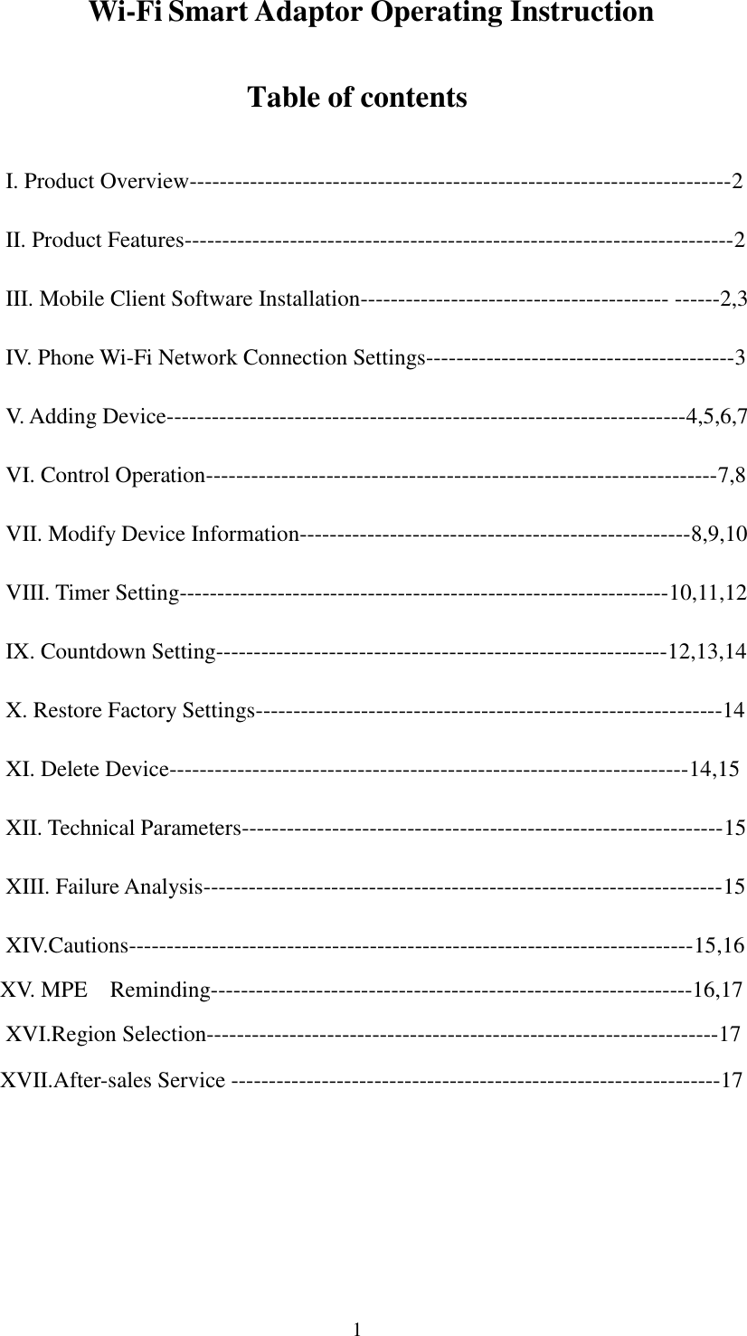
![6 Figure 12 Figure 13 While configuring, the blue LED in front of the product will flash from fast to slow until the LED keeps lighting and "success" is prompted from the phone software to indicate the device is successfully added (Figure 14), which means the successful connection of socket to Wi- Fi router. Figure 14 Figure 15 Click the “Device” button in Figure 14 to enter into Figure 15, by this time, the socket will be automatically added to the device list in the [Device] interface. (Note that if the added device does not appear in the interface. Please click "Refresh" button to refresh.) Method 2 Press and hold the Wi-Fi socket button, and release the button when seeing the blue lamp from quick flashing to slow flashing. Go to the “settings” of cellphone and “open the WLAN settings” and manually connect to GoWin.setup.](https://usermanual.wiki/Cixi-City-Yidong-Electronic/WFU1/User-Guide-2665520-Page-6.png)
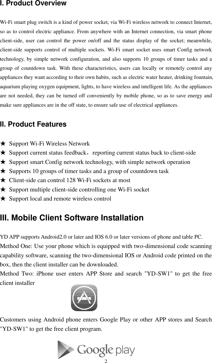
![15 Figure 45 Figure 46 XII. Technical Parameters Voltage: 125VAC, 60Hz Max Load: 15 A, Resistive ,15A General purpose, 10A Tungsten,TV-5,1/2HP WIFI Frequency : 2.4GHz Communication Standard: IEEE802.11b/g/n Security Mechanism: WEP/WPA-PSK/WPA2-PSK, TKIP Communication range/distance: using in the normal Wi-Fi signal environment Product Type: WFU-1 Software Version: YD -SW1 Operating temperature 0 oC to +35 oC XIII. Failure Analysis 1. Check if the power socket connection is normal 2. Check if the phone is connected to WIFI network 3. If the WIFI password input while configuring is correct 4. Refer to client-side [FAQ] for specific issues XIV. Cautions This device complies with Part 15 of the FCC Rules / Industry Canada licence-exempt RSS standard(s). Operation is subject to the following two conditions: (1) this device may not cause harmful interference, and (2) this device must accept any interference received, including interference that may cause undesired operation. Le présent appareil est conforme aux CNR d'Industrie Canada applicables aux appareils radio exempts de licence. L'exploitation est autorisée aux deux conditions suivantes : (1) l'appareil ne doit pas produire de brouillage, et (2) l'utilisateur de l'appareil doit accepter tout brouillage radioélectrique subi, même si le brouillage est](https://usermanual.wiki/Cixi-City-Yidong-Electronic/WFU1/User-Guide-2665520-Page-15.png)