Comar Systems CSB200 Class B AIS Transponder User Manual CSB200 R3 1
Comar Systems Ltd Class B AIS Transponder CSB200 R3 1
UserManual.wiki
>
Comar Systems
>
CSB200 User Manual
>
User manual
Contents
1.
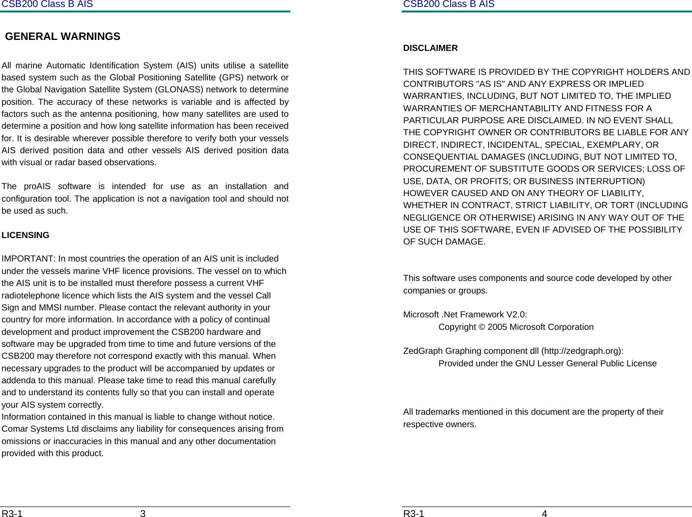
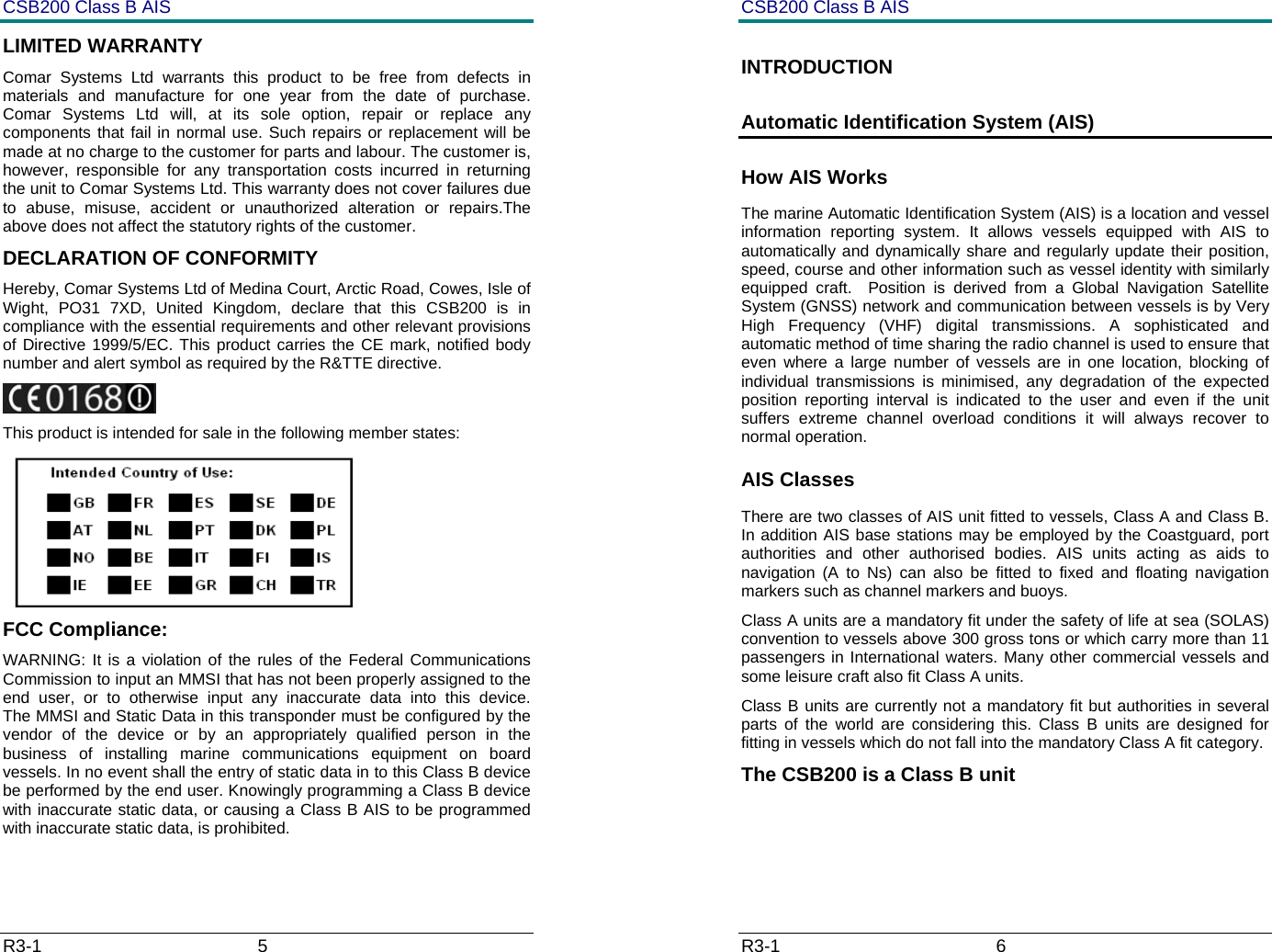
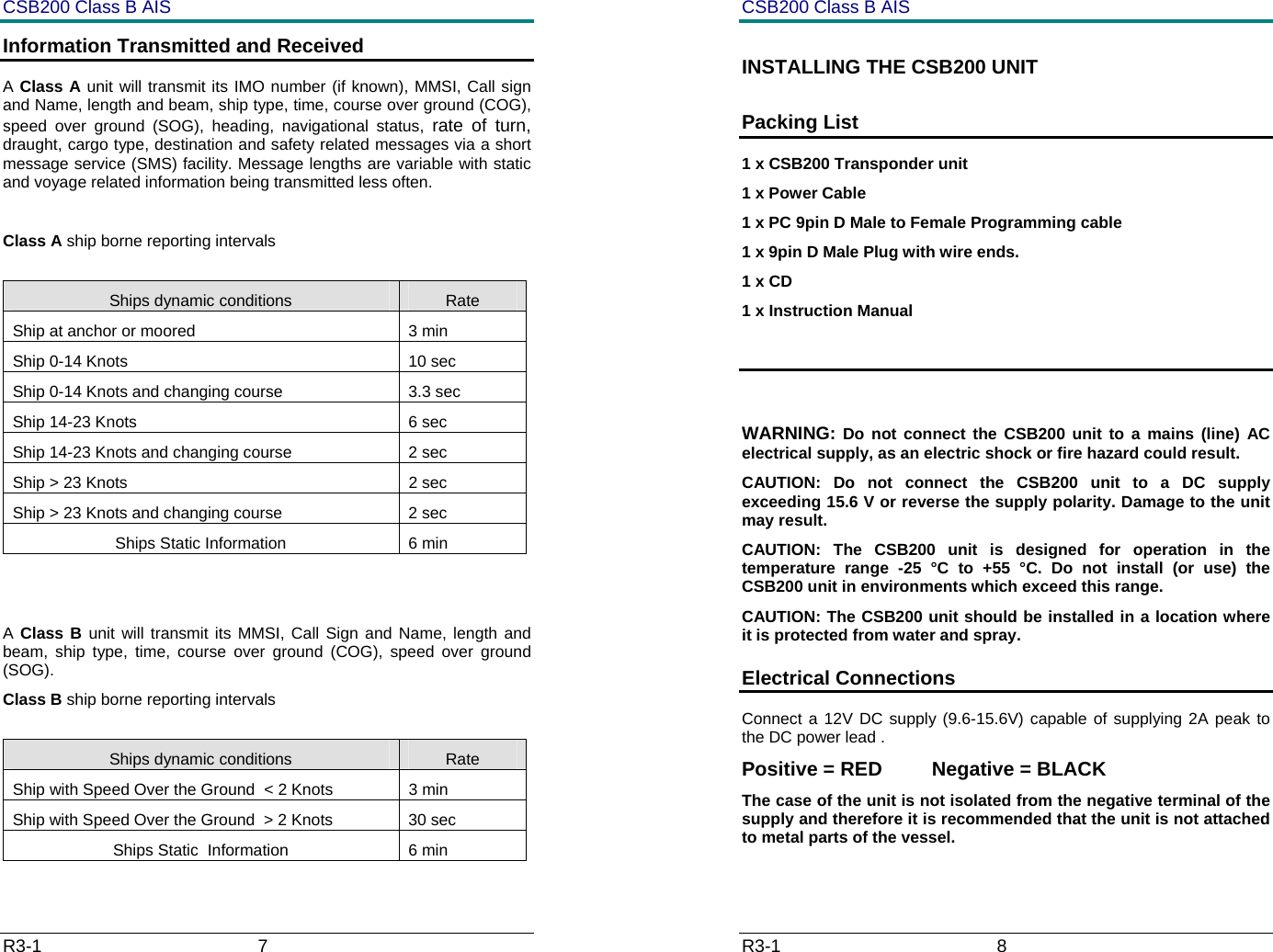
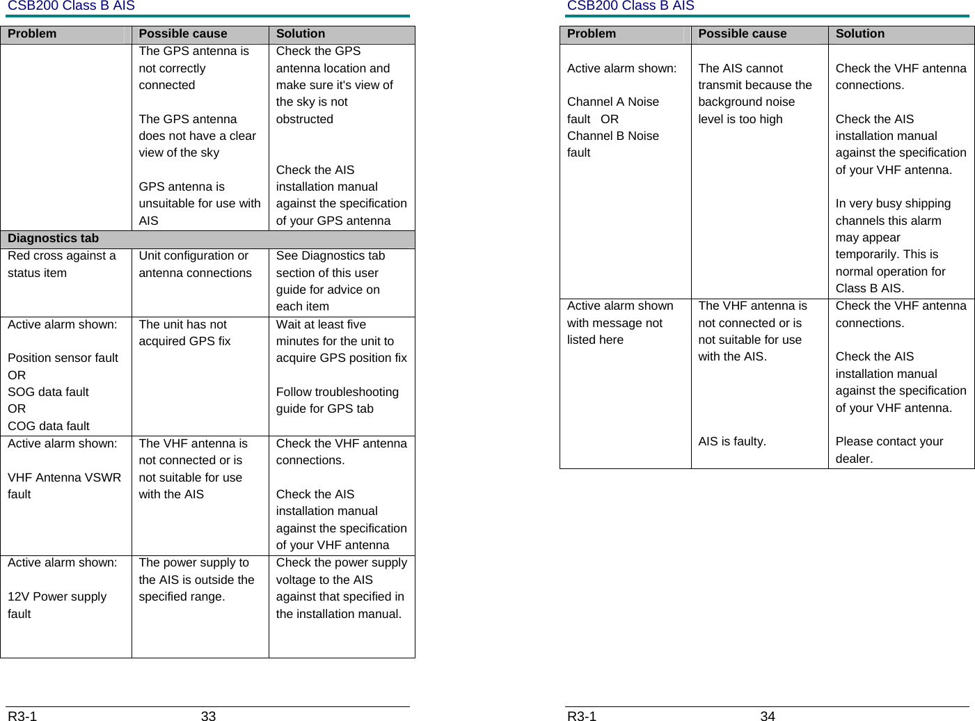
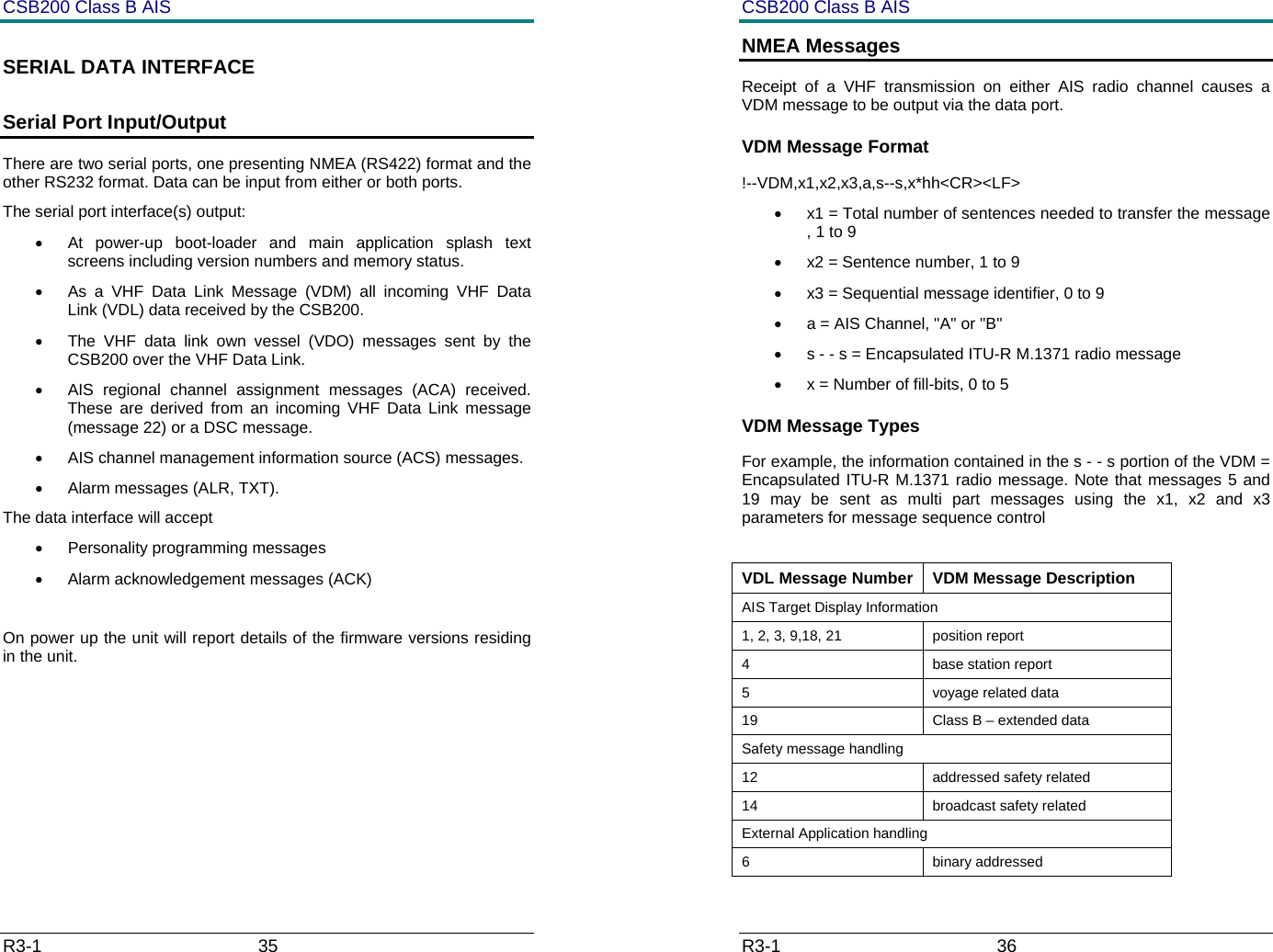
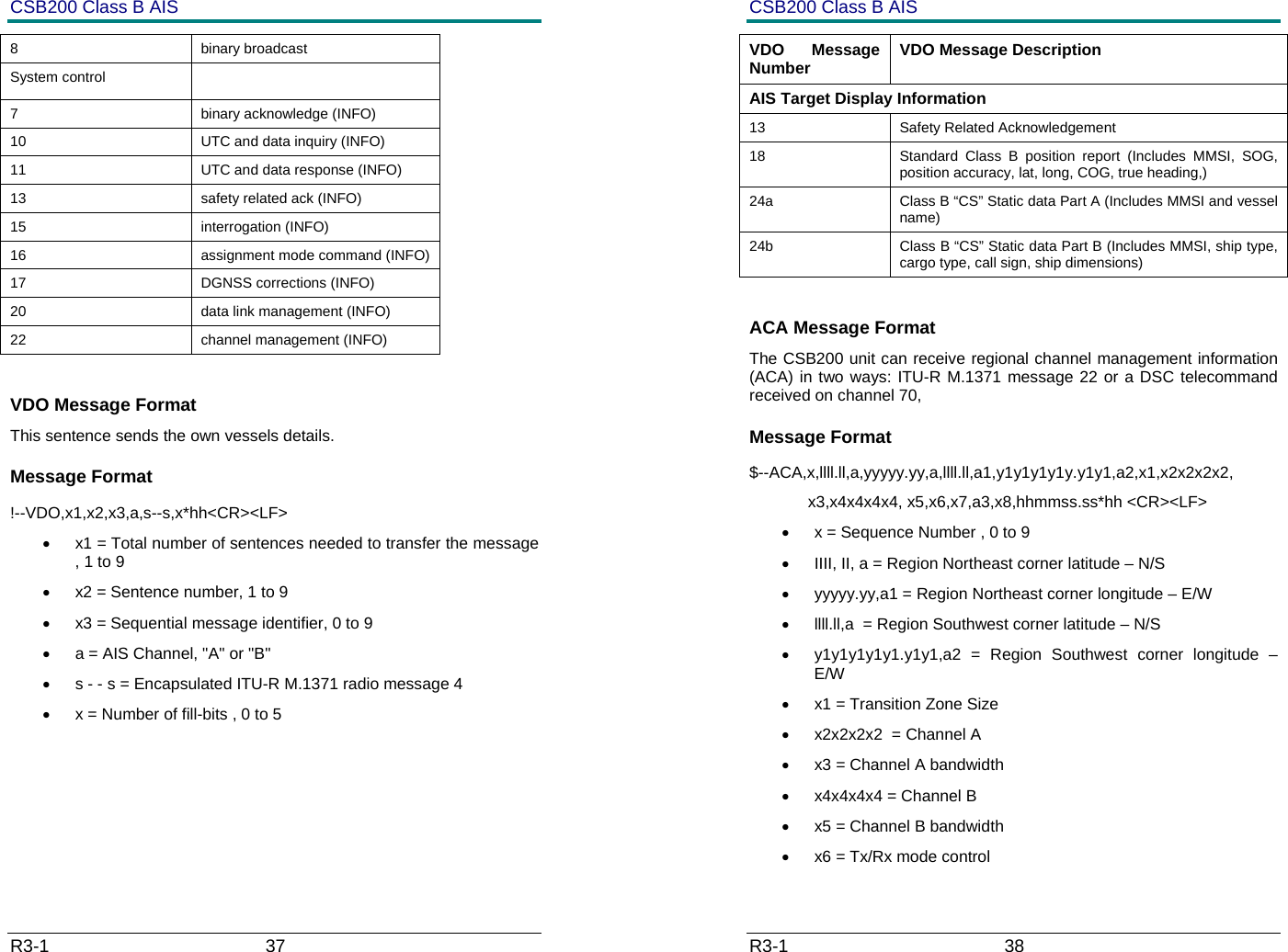
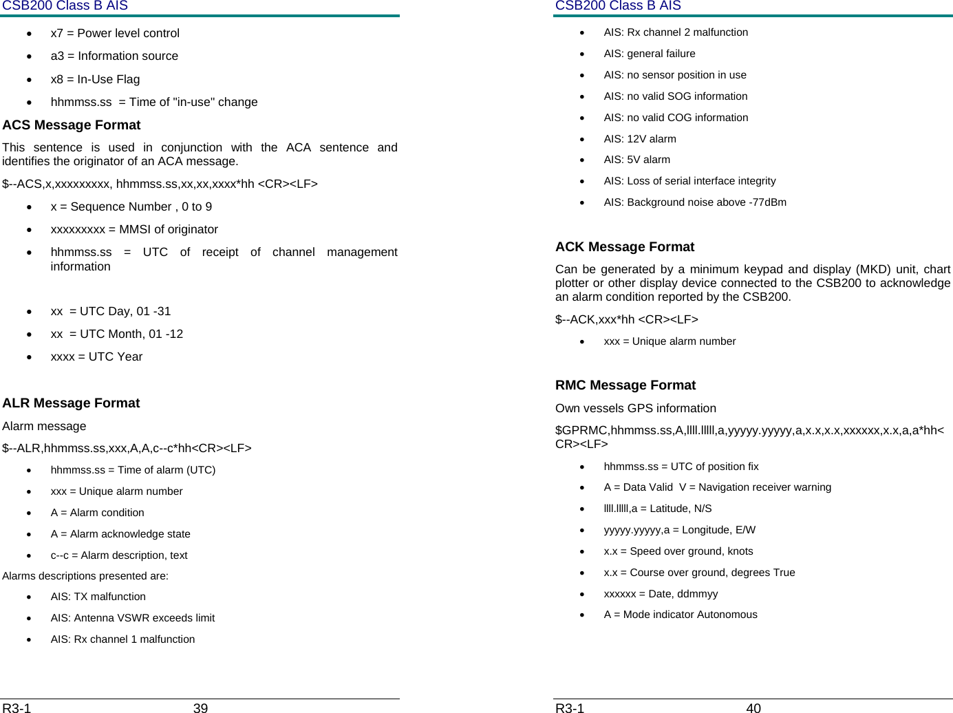
Manual inc Operational description
2.
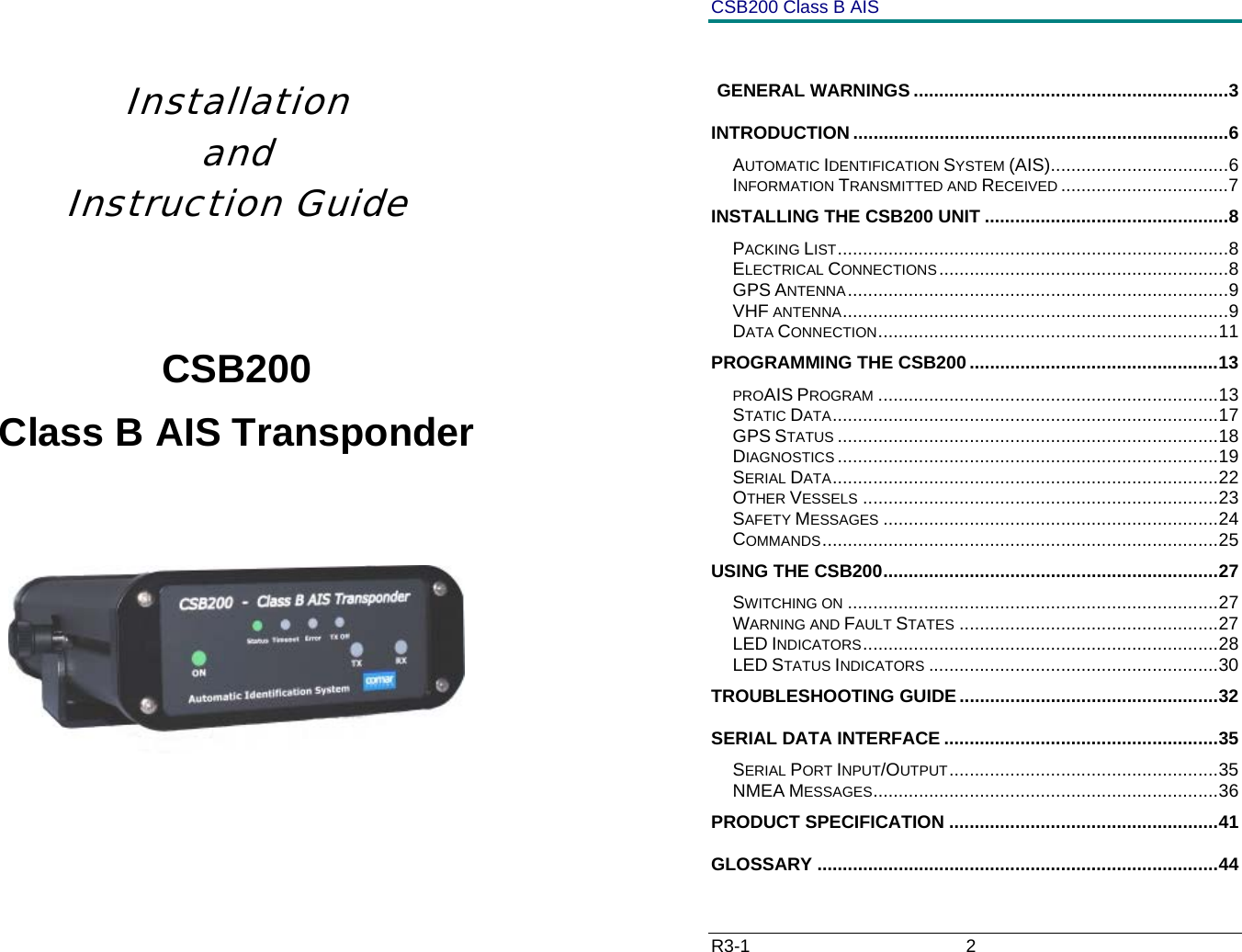
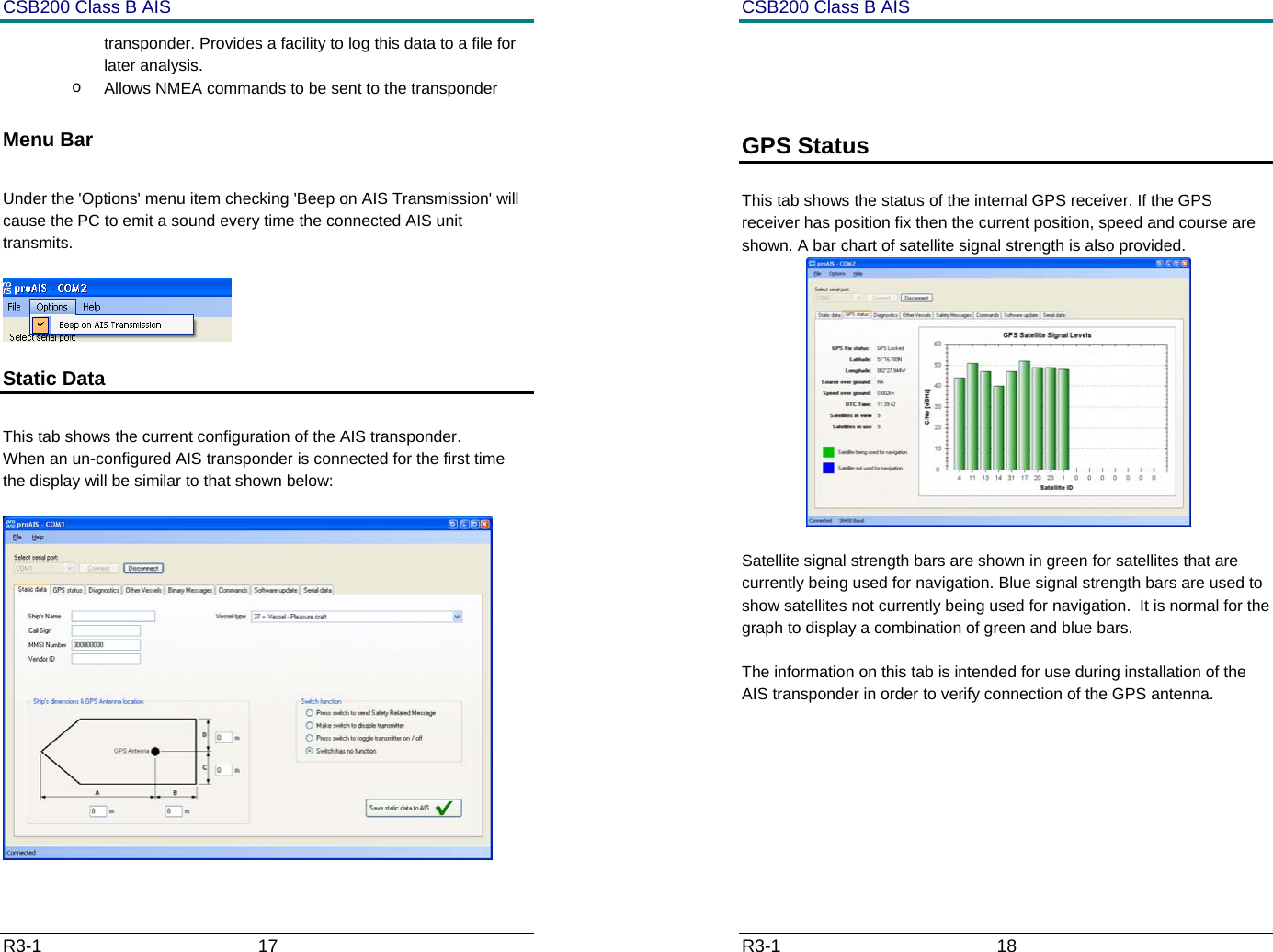
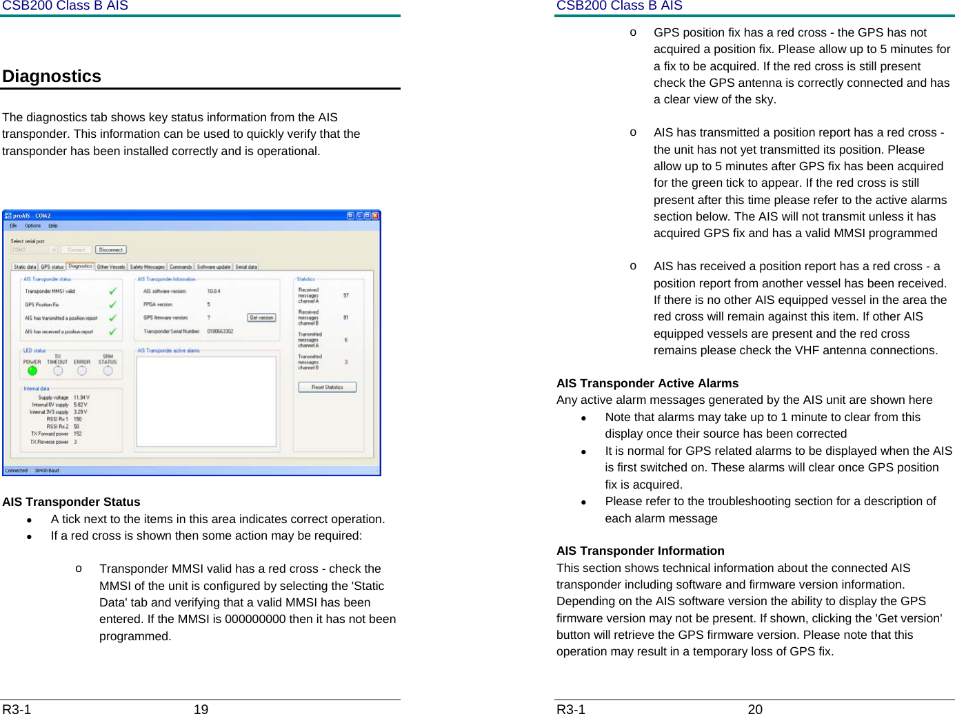
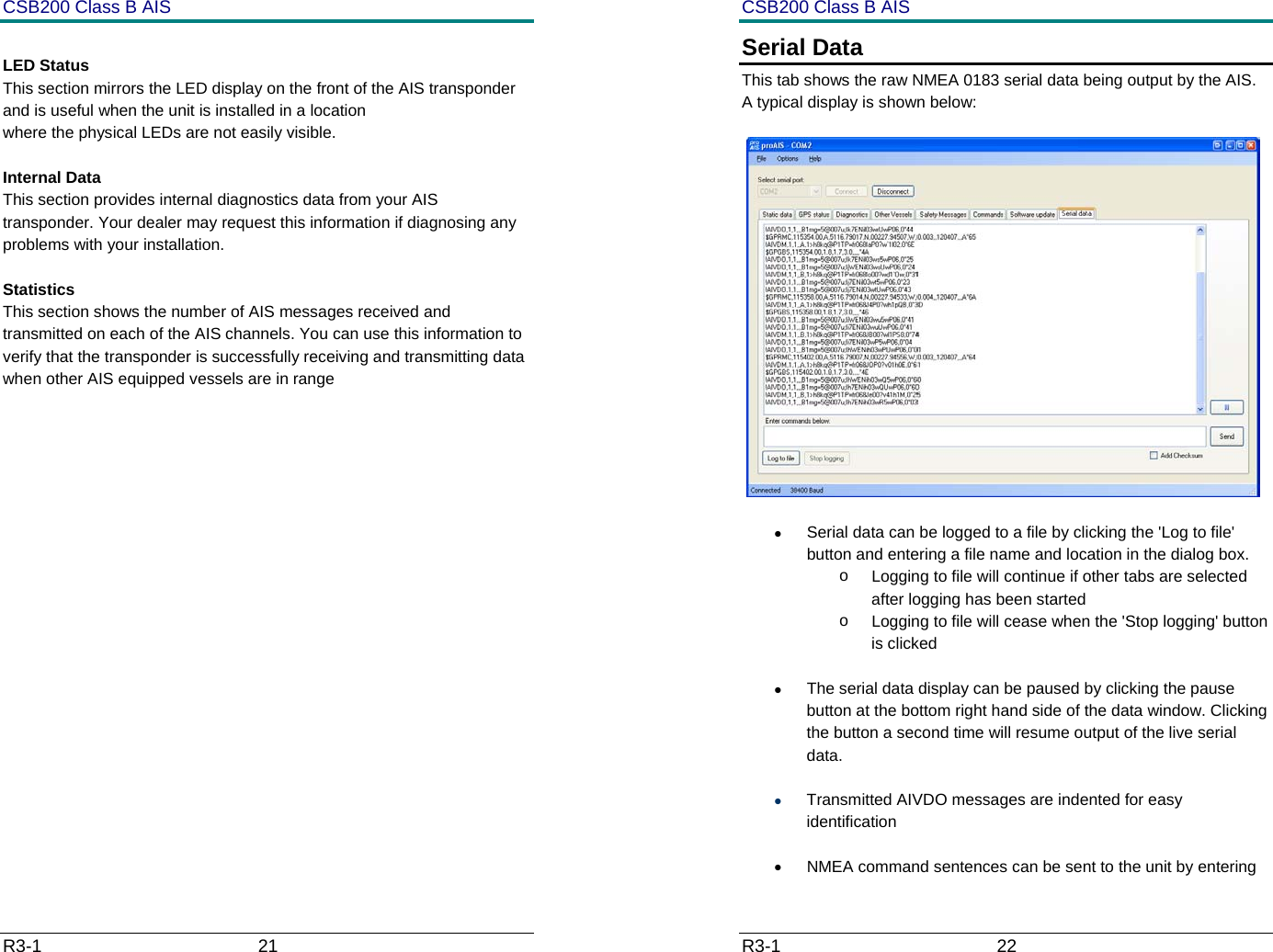
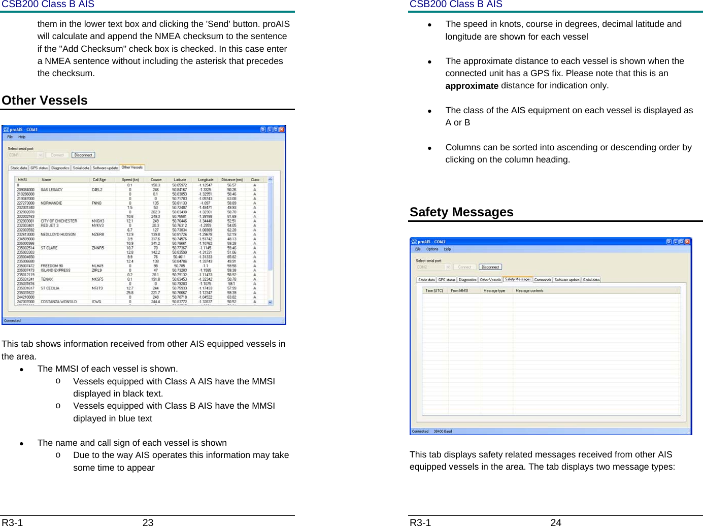
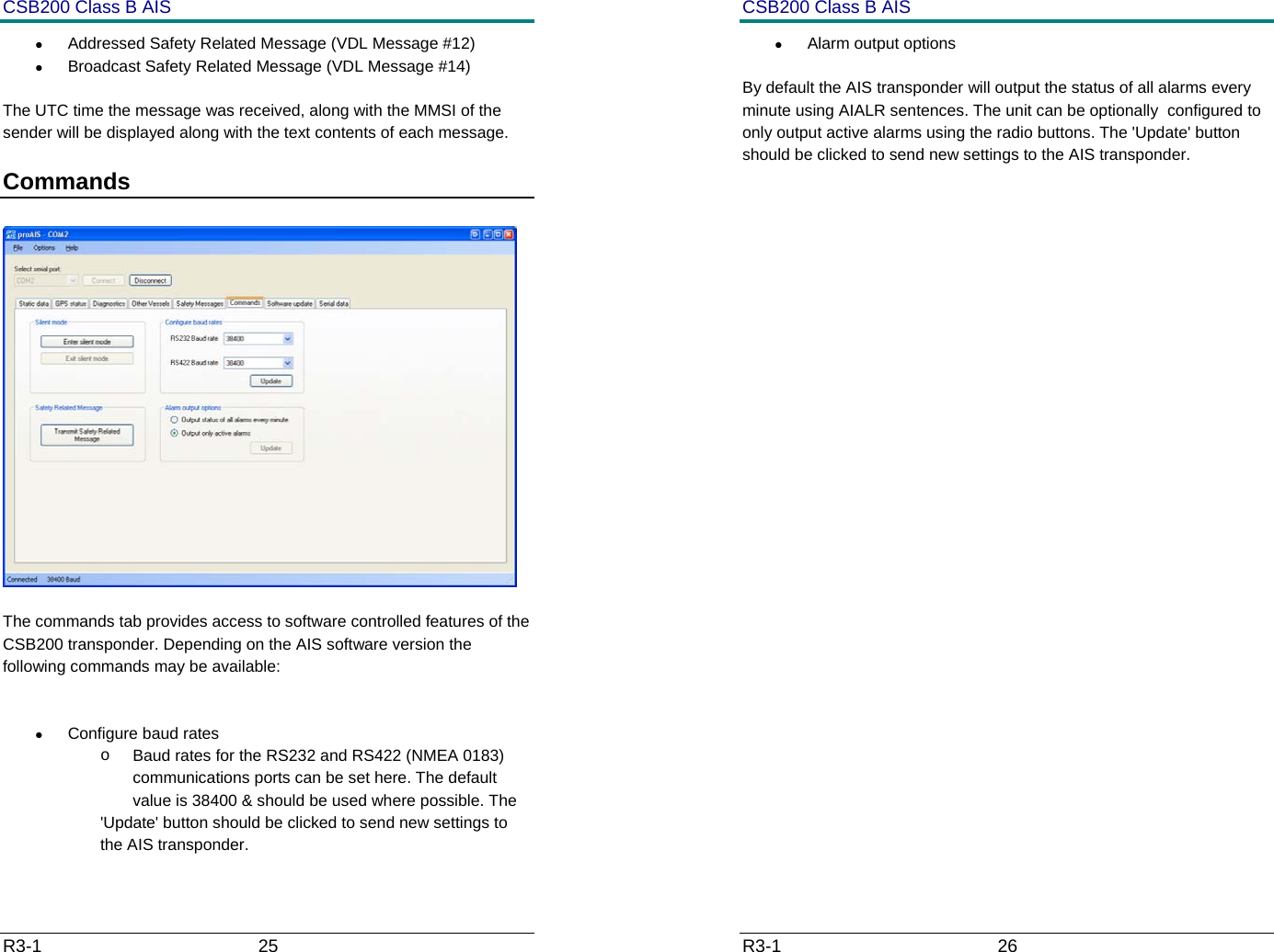
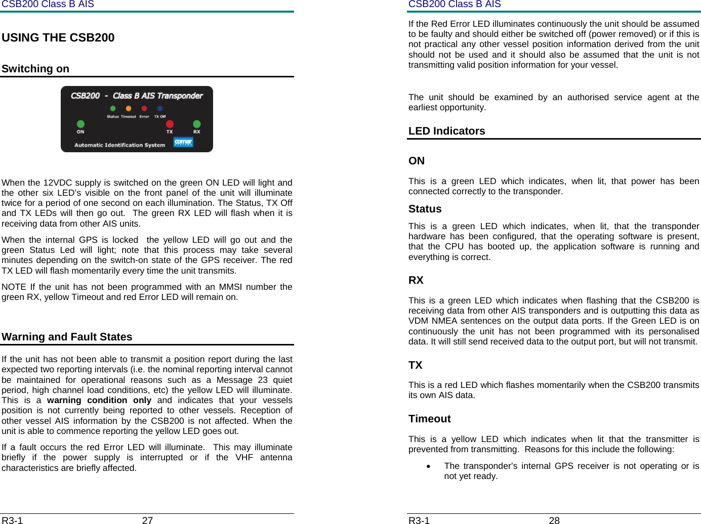
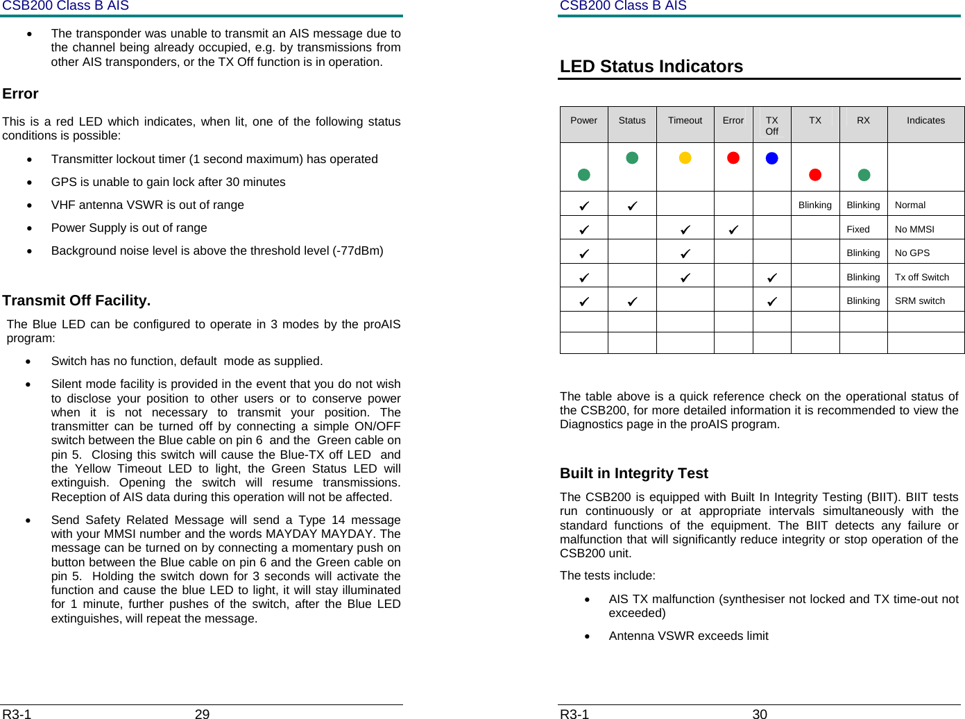
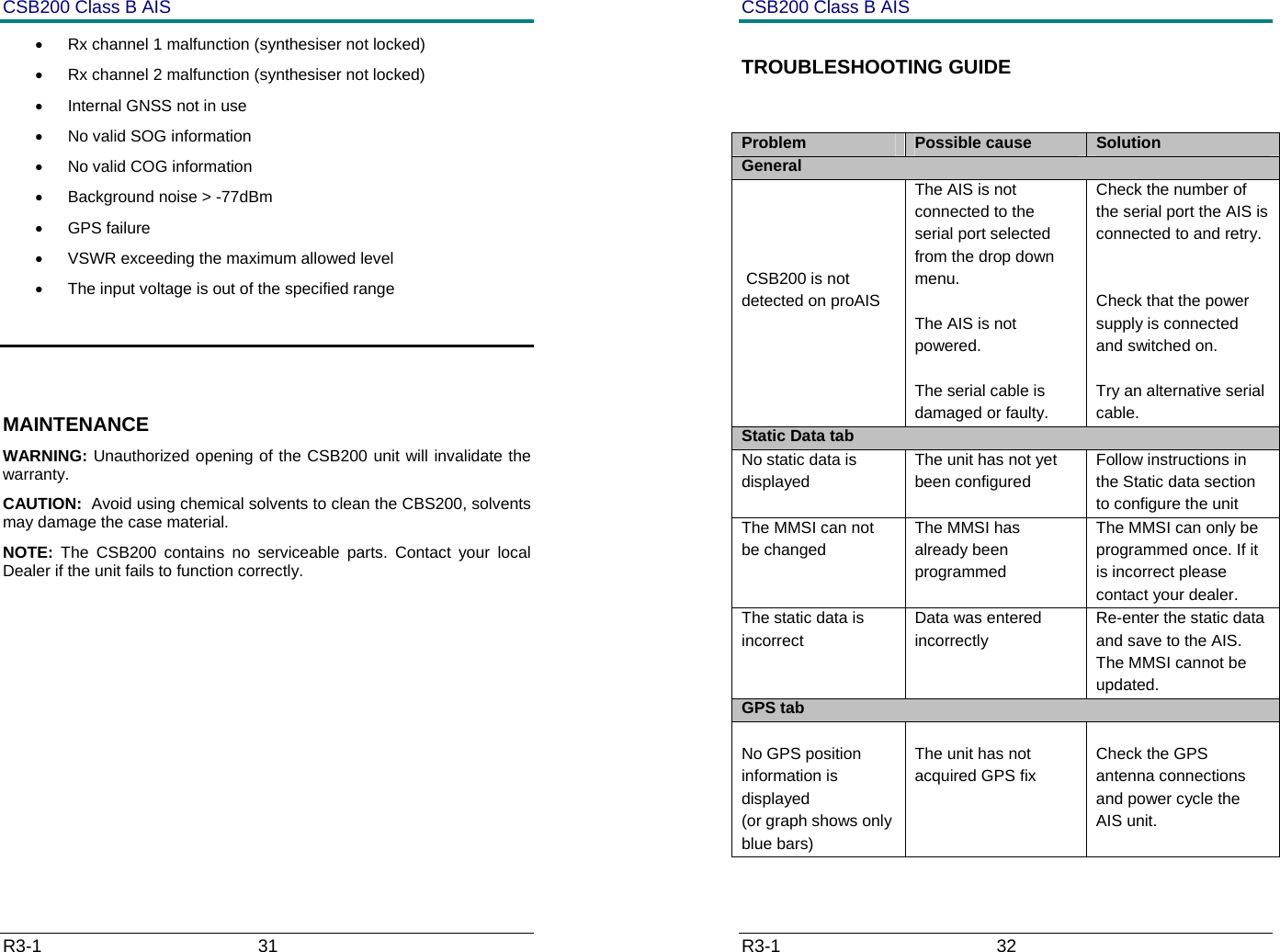
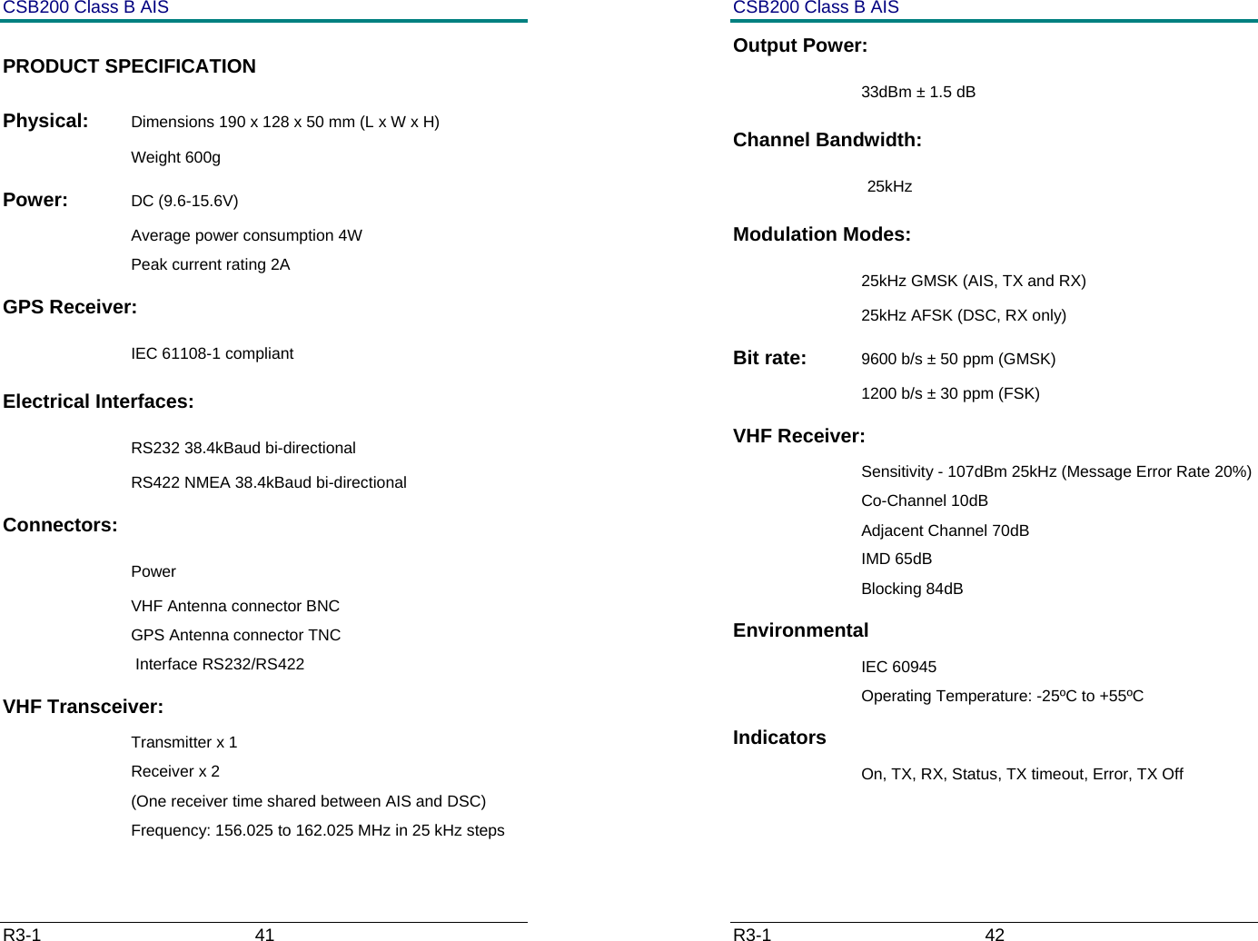
User manual
3.
Programming Manual
User manual
Navigation menu
Upload a User Manual
Namespaces
Wiki Guide
HTML
PDF
Info
Views
User Manual
Discussion / Help
Navigation