DareGlobal Technologies A4001N ADSL2+ ROUTER WIFI 11n 2x2 User Manual N22 2x2 User Manual
Shanghai DareGlobal Technologies Co., Ltd. ADSL2+ ROUTER WIFI 11n 2x2 N22 2x2 User Manual
UserManual.wiki
>
DareGlobal Technologies
>
A4001N User Manual
User Manual
Navigation menu
Upload a User Manual
Namespaces
Wiki Guide
HTML
PDF
Info
Views
User Manual
Discussion / Help
Navigation
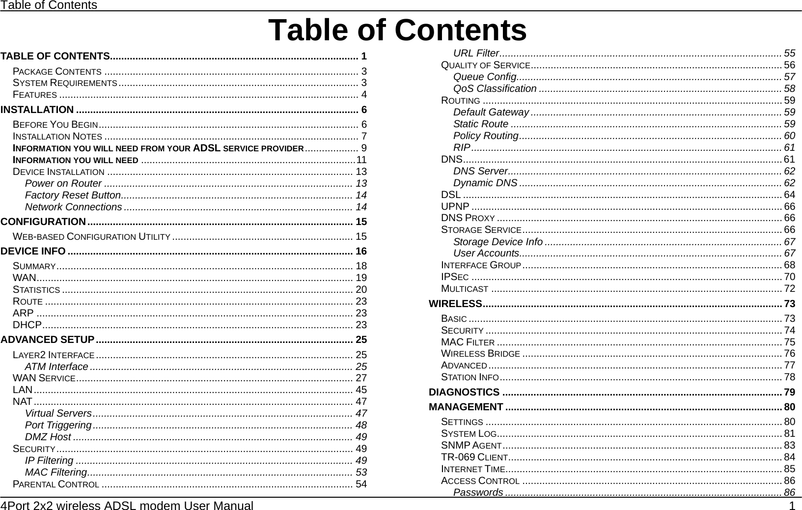
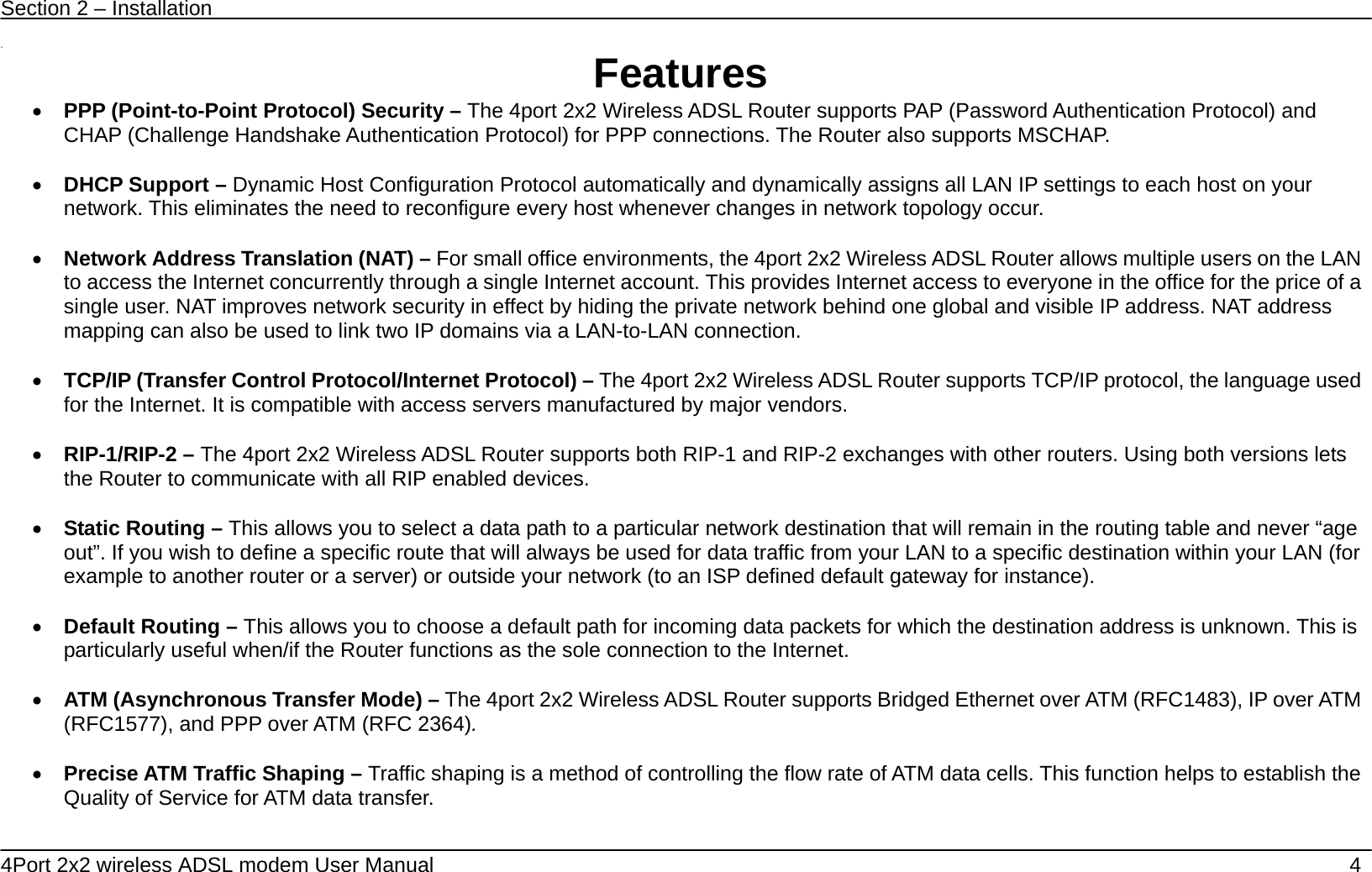
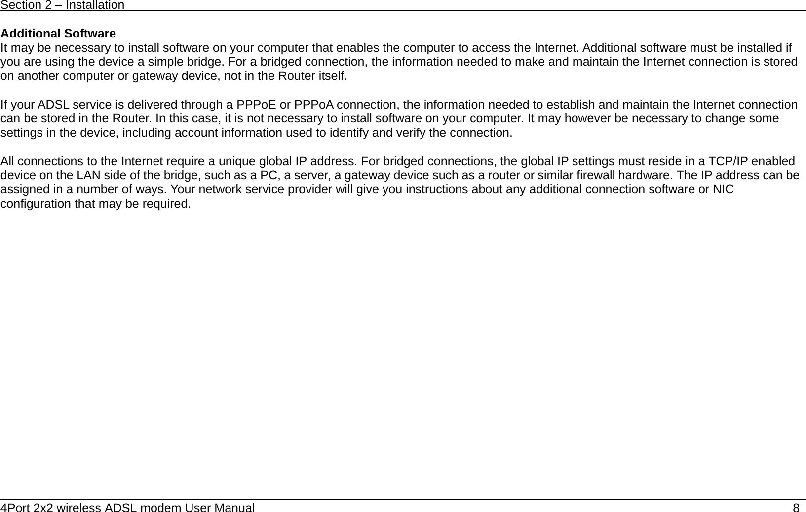
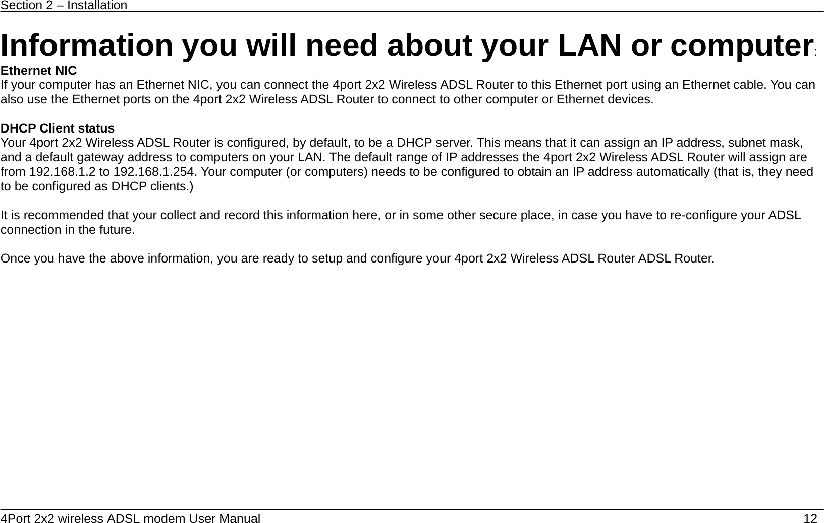
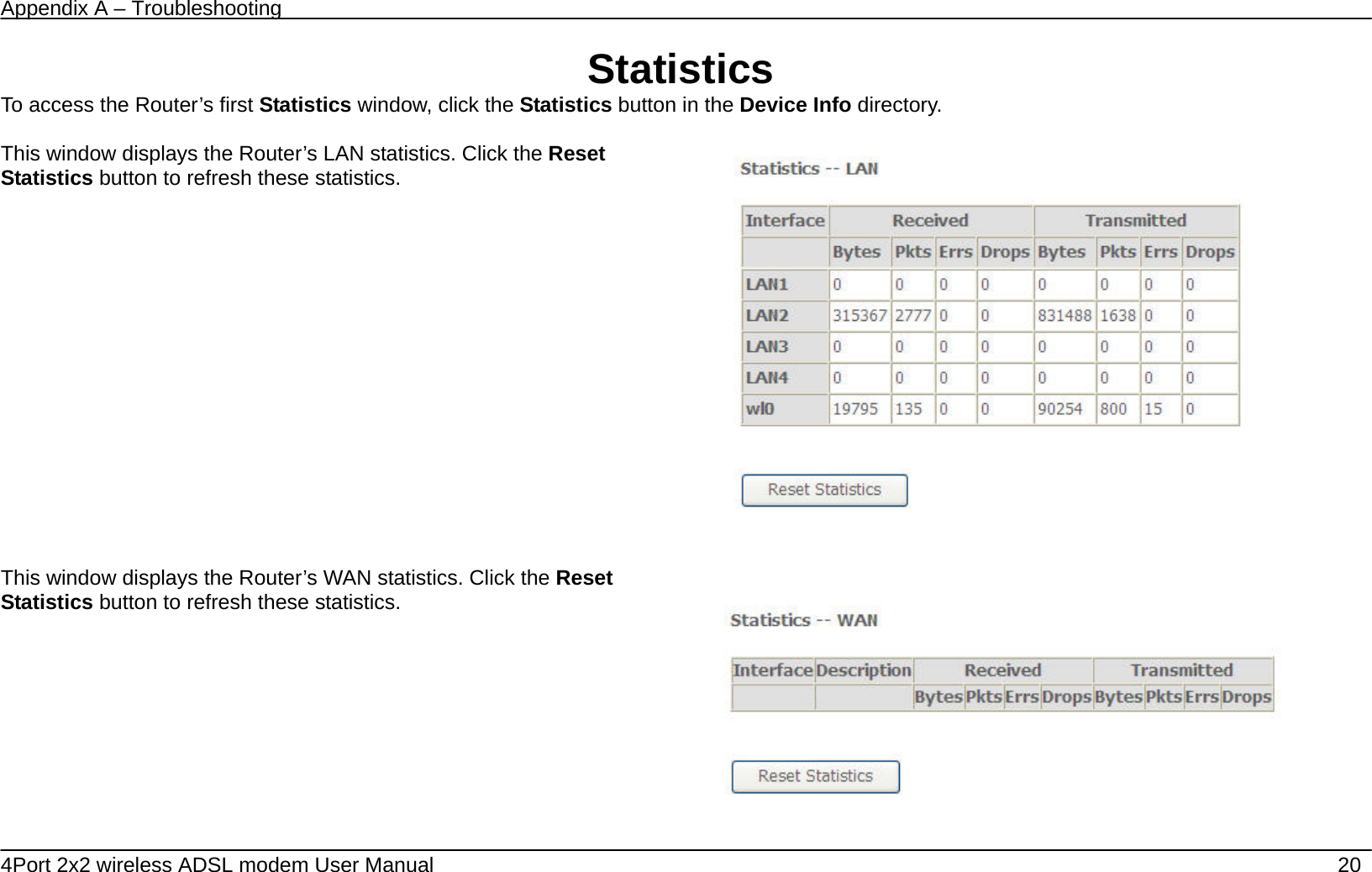
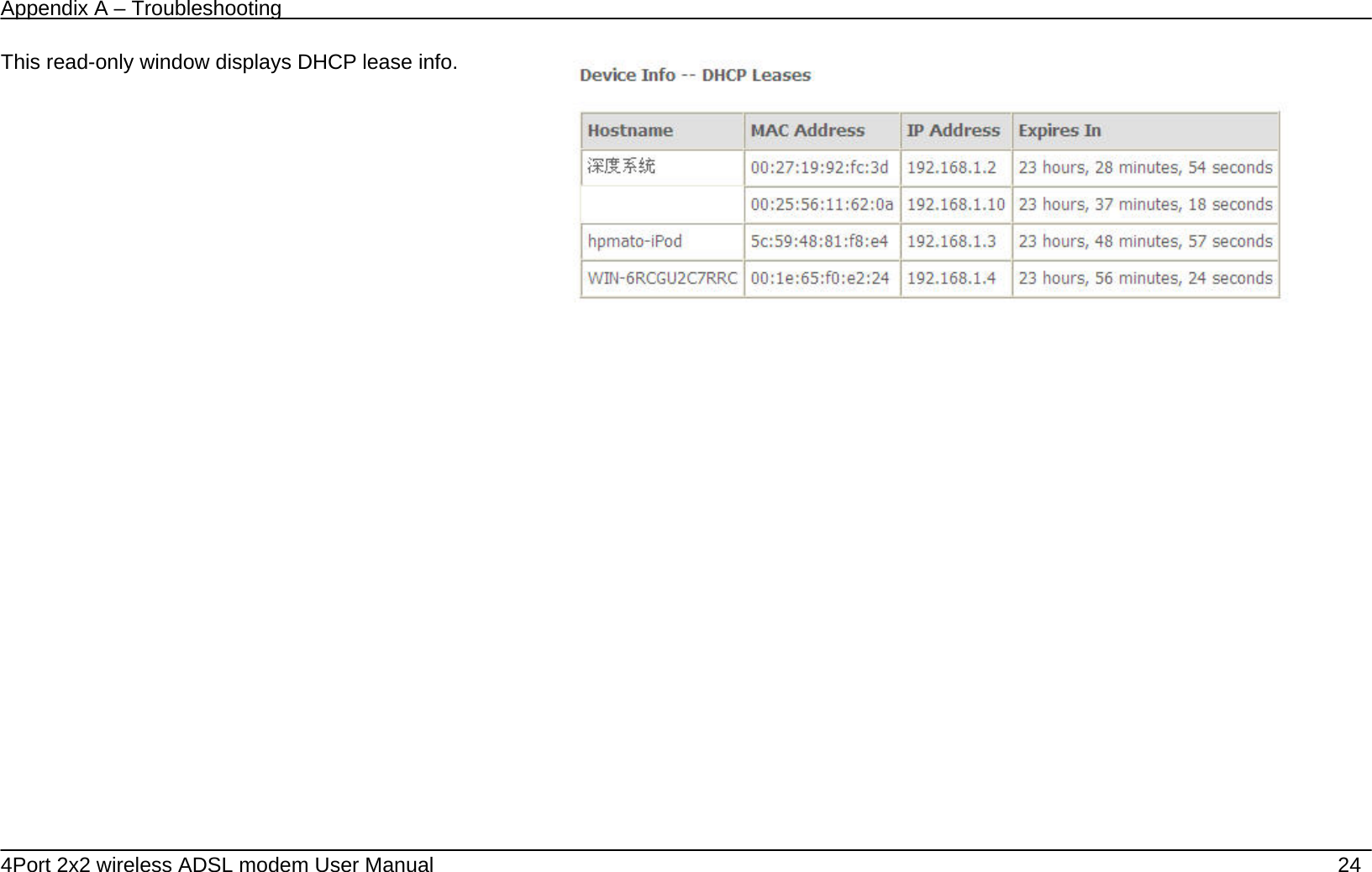
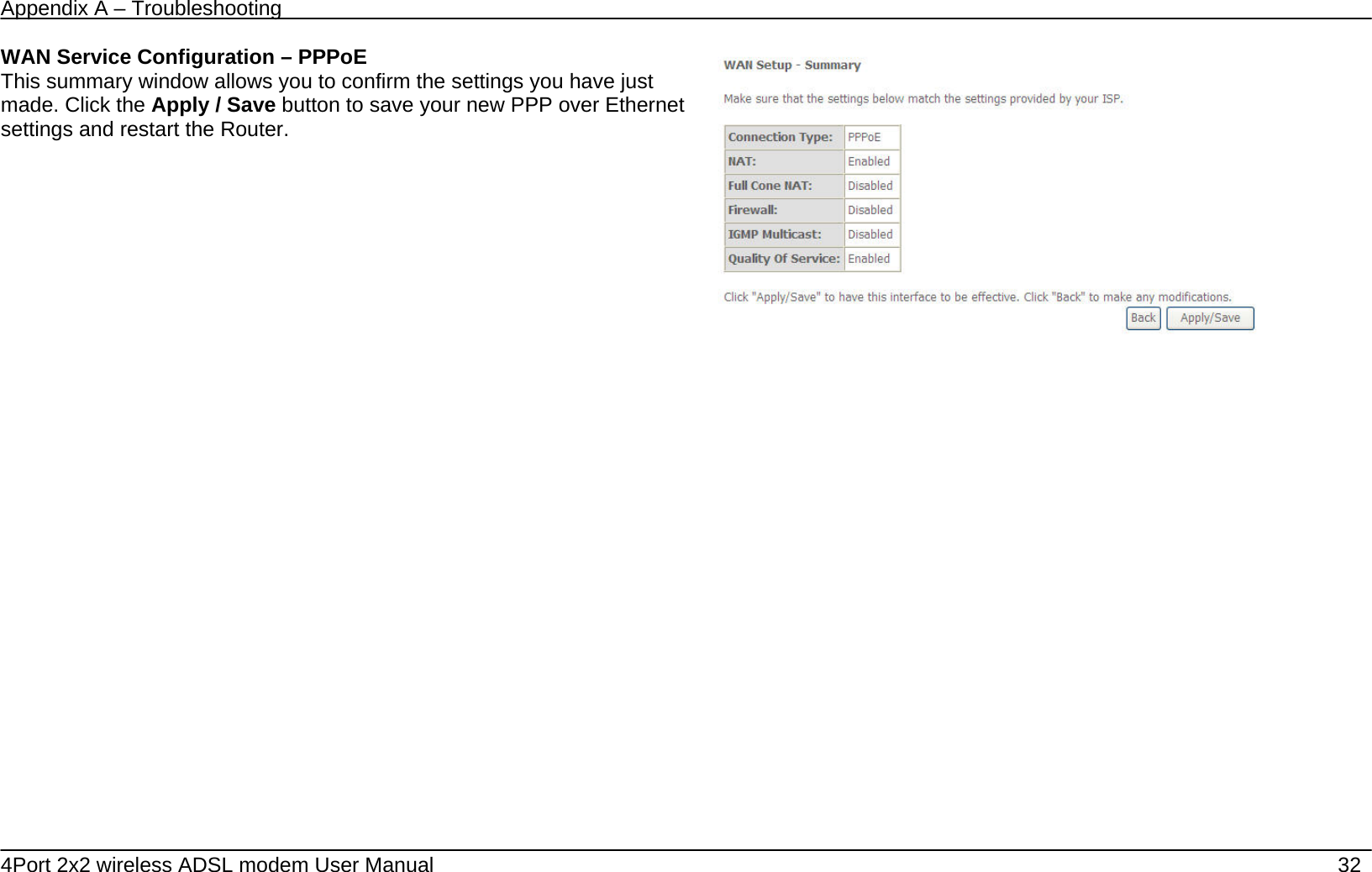
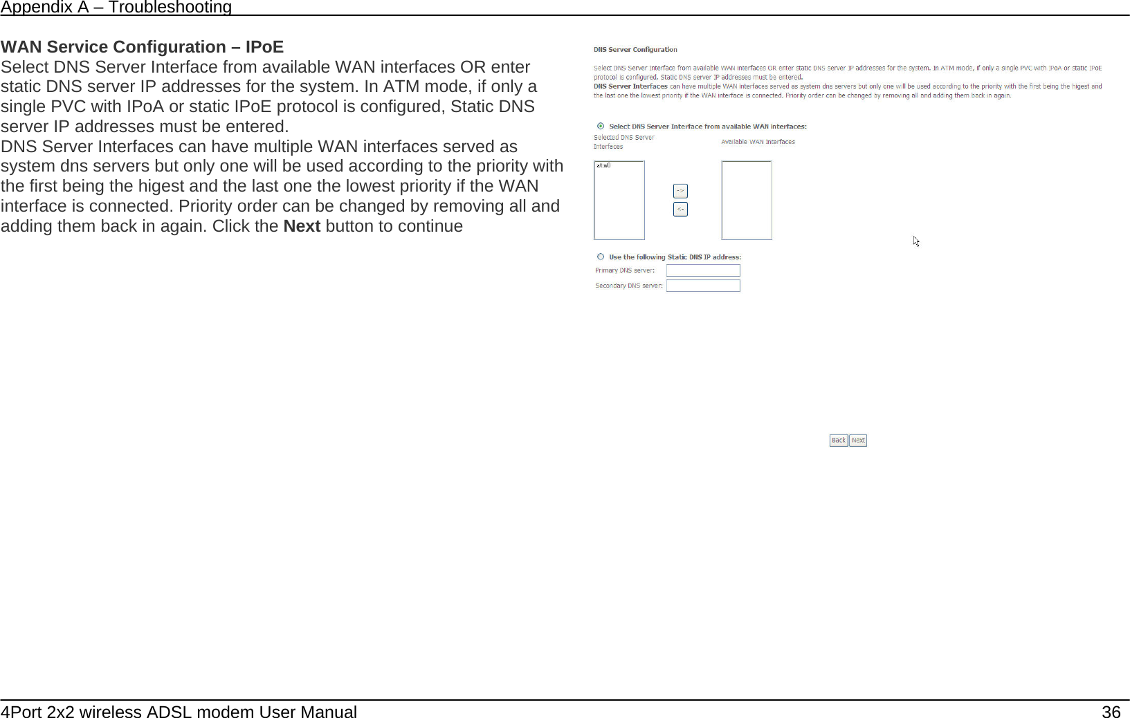
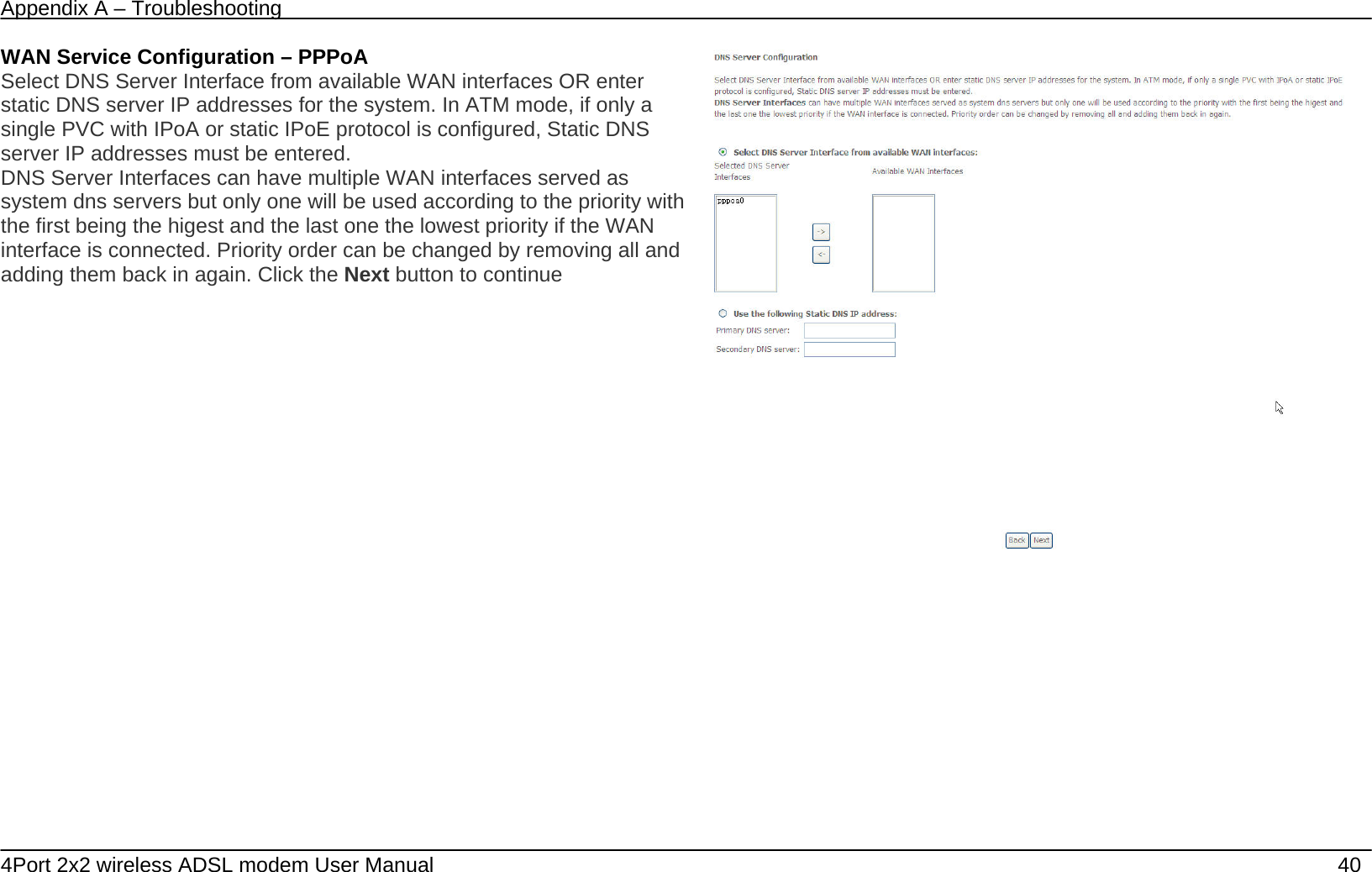
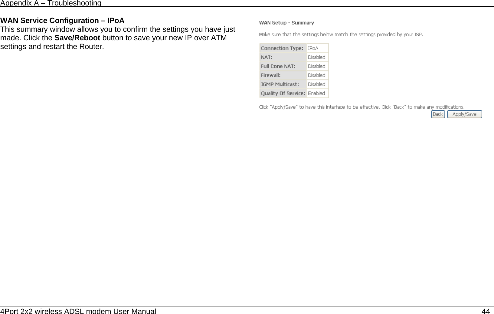
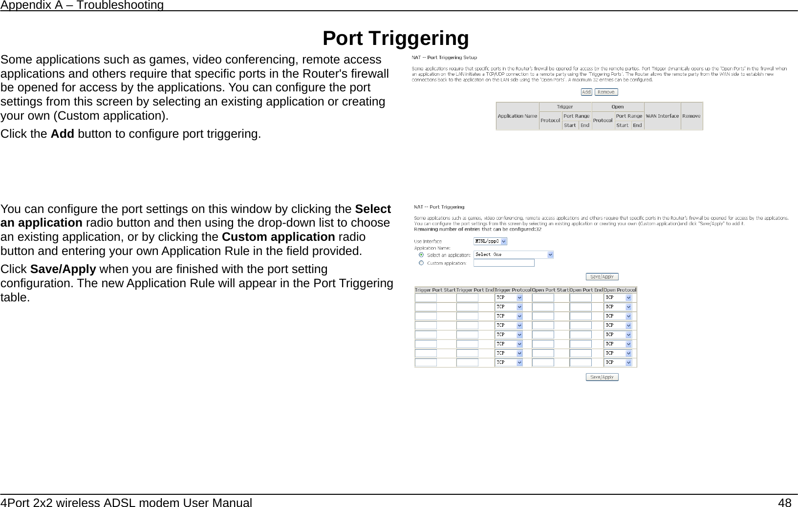
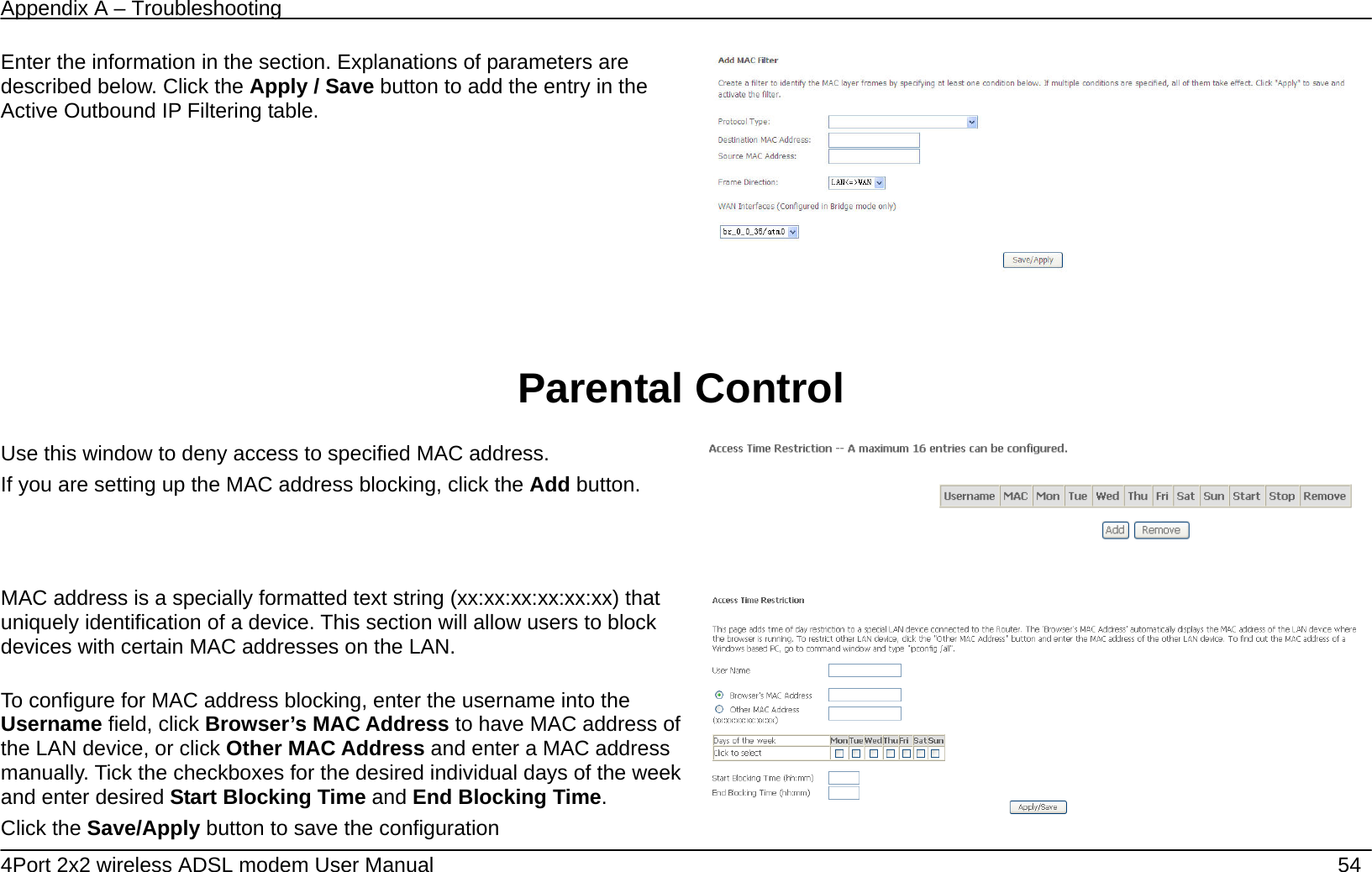
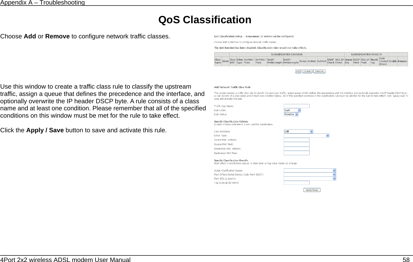
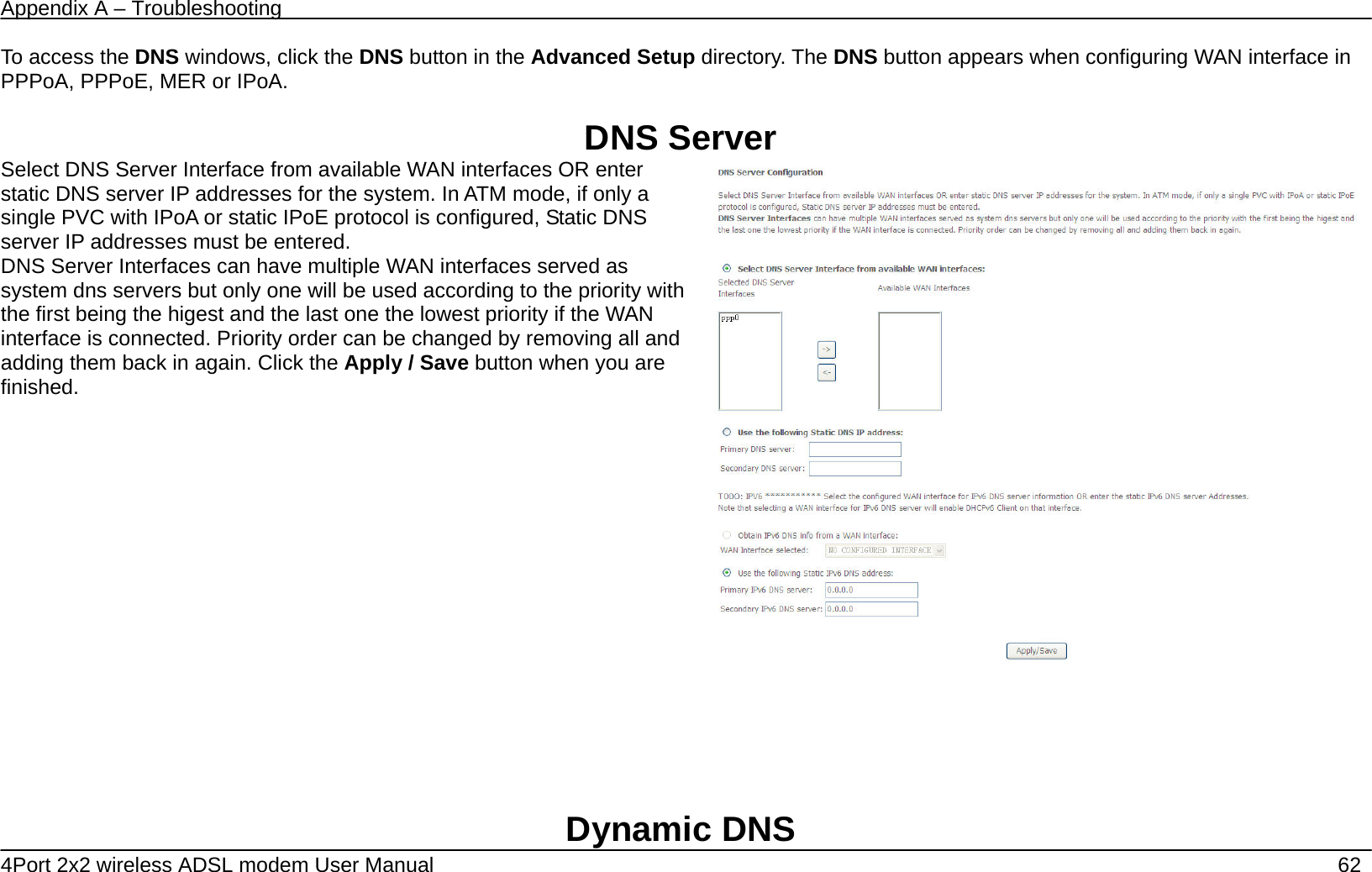
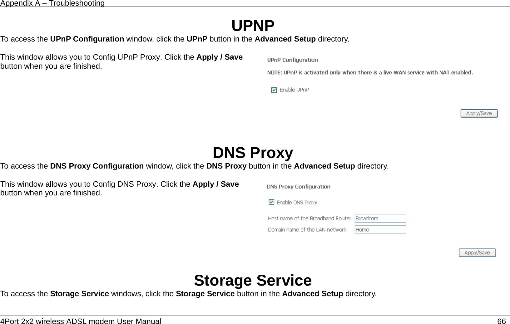
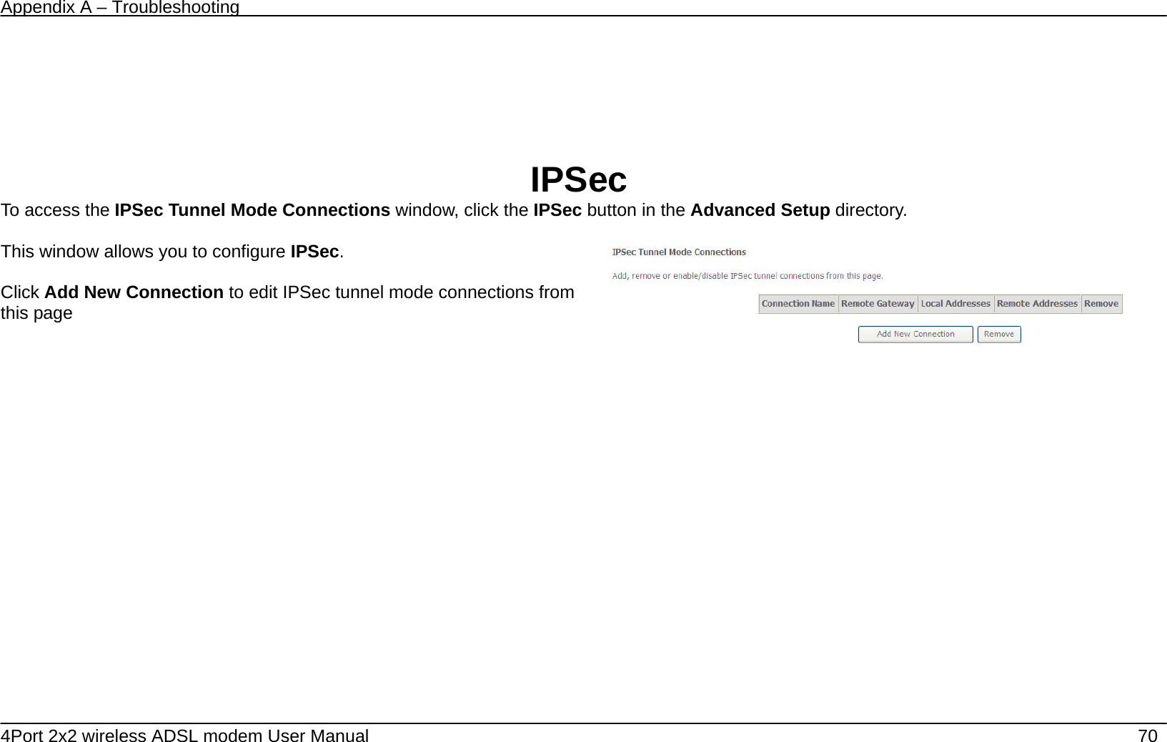
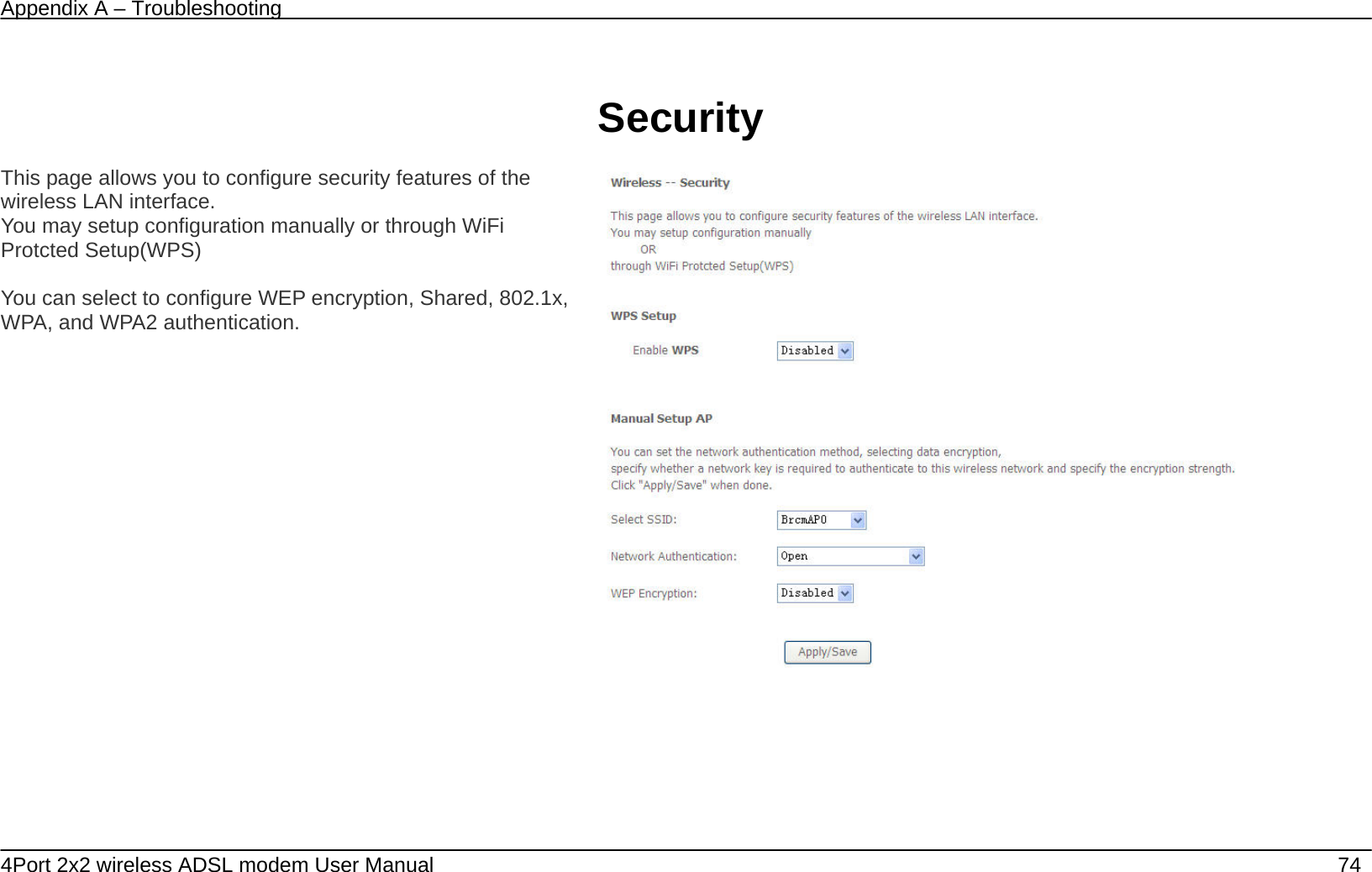
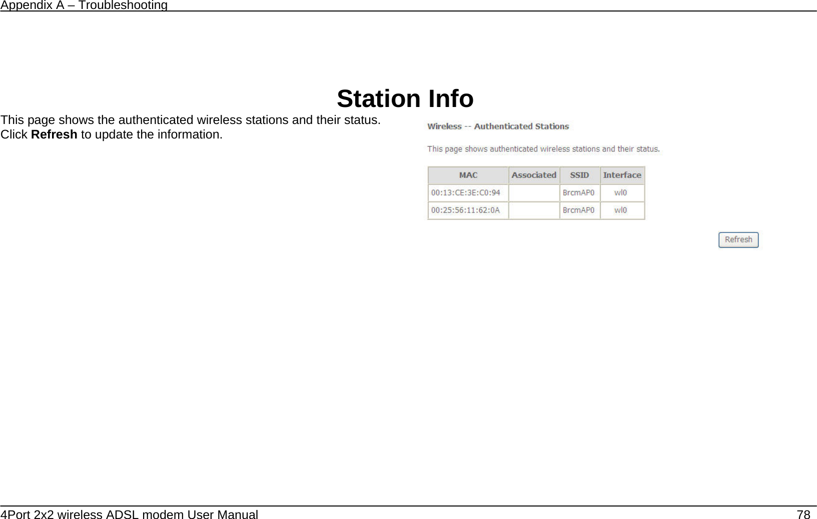
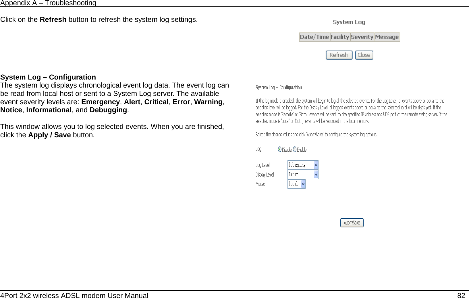
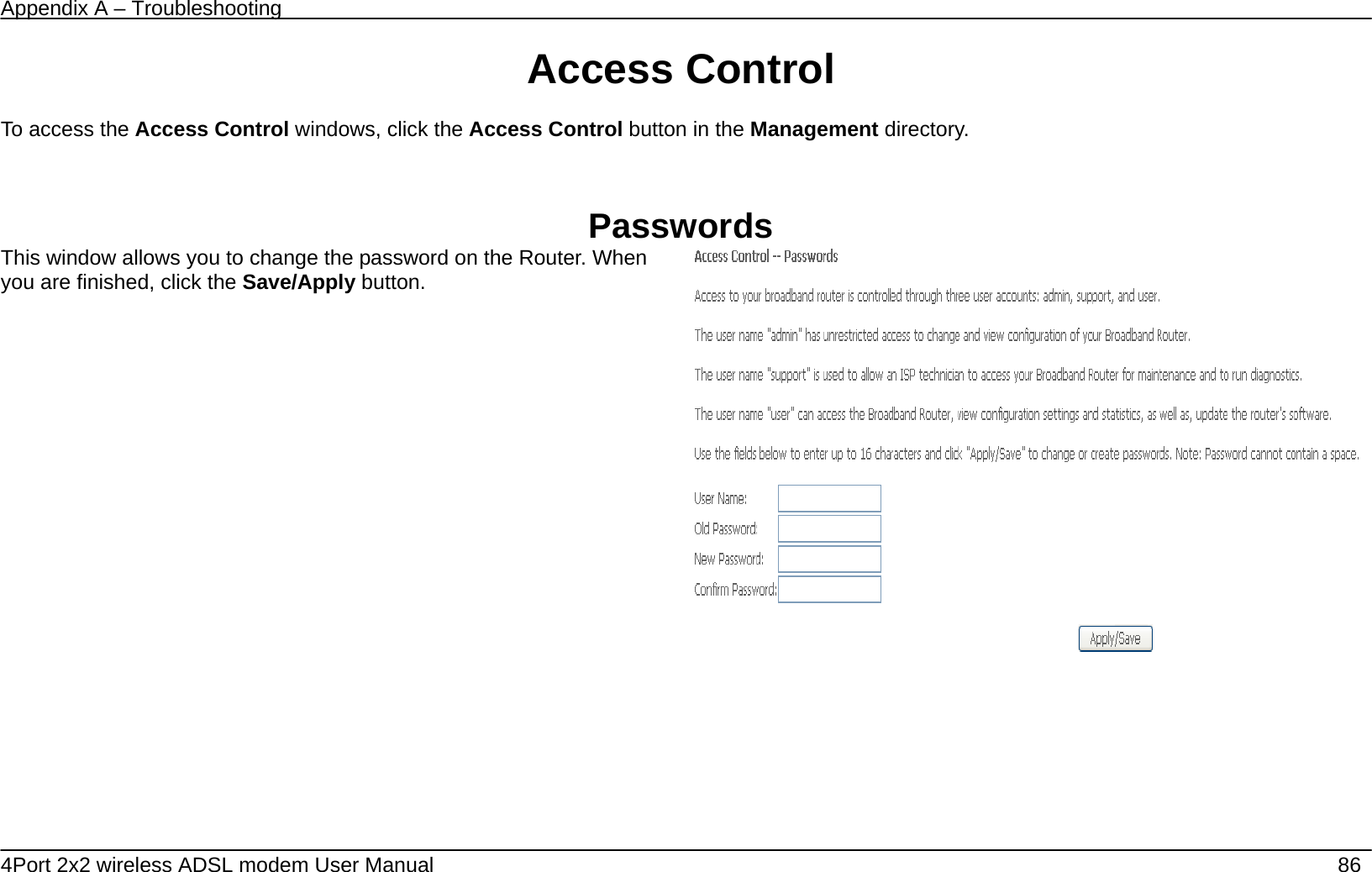
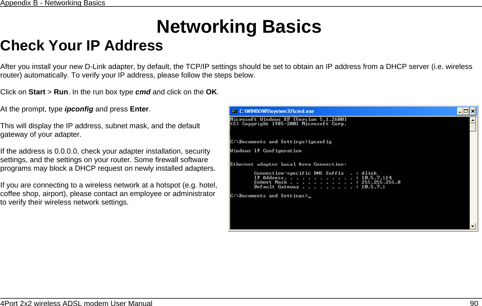
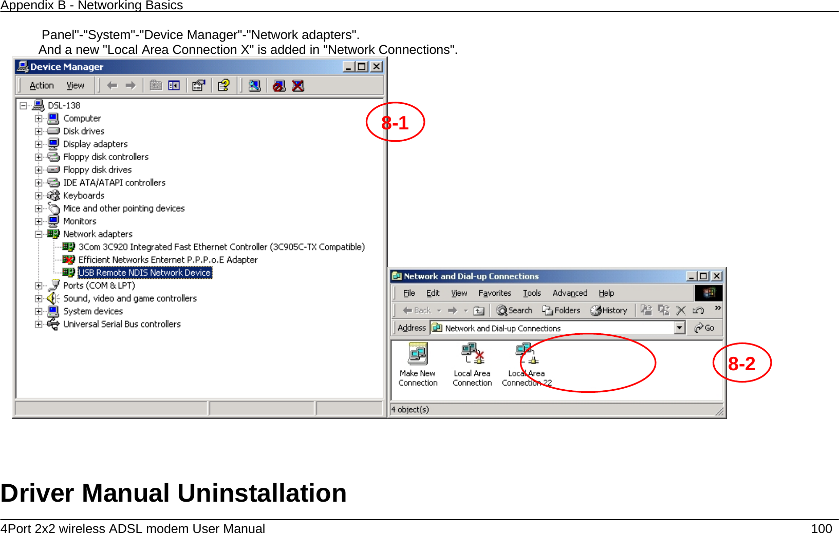
![Appendix A – Troubleshooting 4Port 2x2 wireless ADSL modem User Manual 51 Filters Parameter Description Filter Name Enter a name for the new filter. IP Version Ipv4/Ipv6 Protocol Select the transport protocol (Any, TCP/UDP, TCP, UDP or ICMP) that will be used for the filter rule. Source IP address[/prefix length] Enter the start IP address which you are creating the filter rule. Source Port (port or port:port) The Source Port is the TCP/UDP port on either the LAN or WAN depending on if you are configuring an Outbound or Inbound Filter rule. Destination IP address[/prefix length] Enter the end IP address which you are creating the filter rule. Destination Port (port or port:port) The Destination Port is the TCP/UDP port on either the LAN or WAN depending on if you are configuring an Outbound or Inbound Filter rule. IP Filtering – Incoming This window allows you to create a filter rule of Incoming. Click change default policy to change the mode of policy. Now default policy is ACCEPT, it means all incoming IP traffic from WAN is accepted, but some IP traffic can be blocked by setting up filters. If you are setting up the incoming IP filtering, click the Add button.](https://usermanual.wiki/DareGlobal-Technologies/A4001N/User-Guide-1971182-Page-51.png)
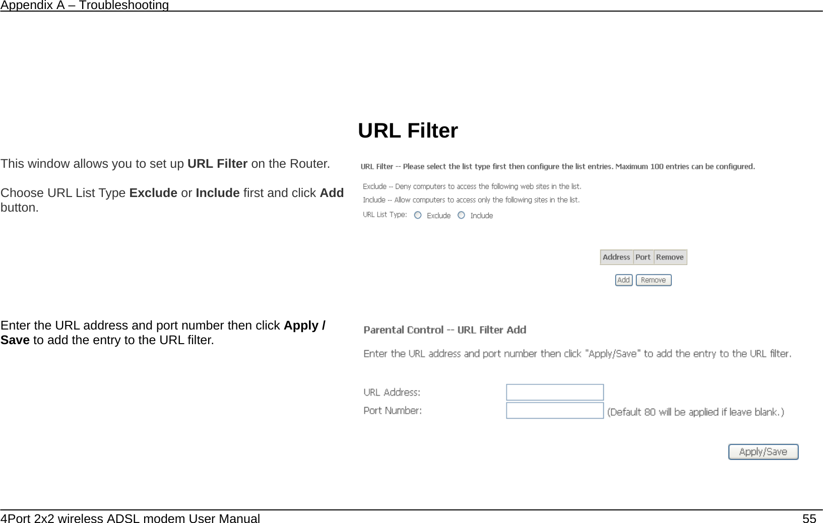
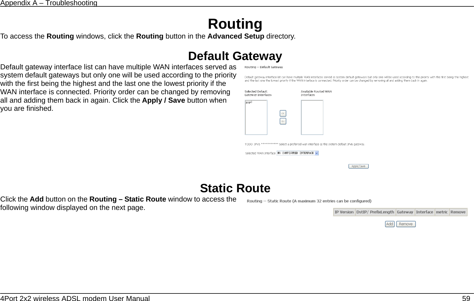
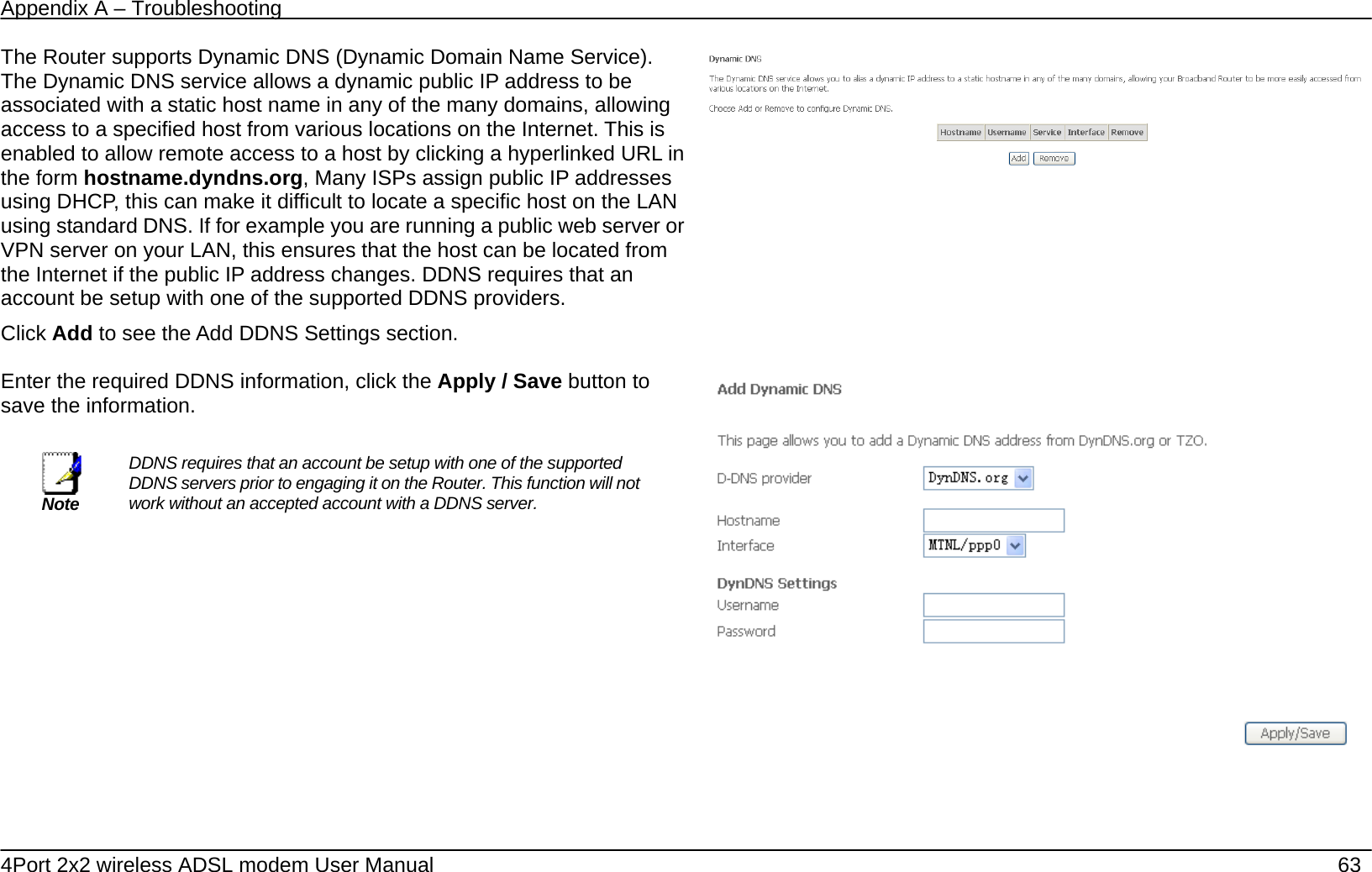
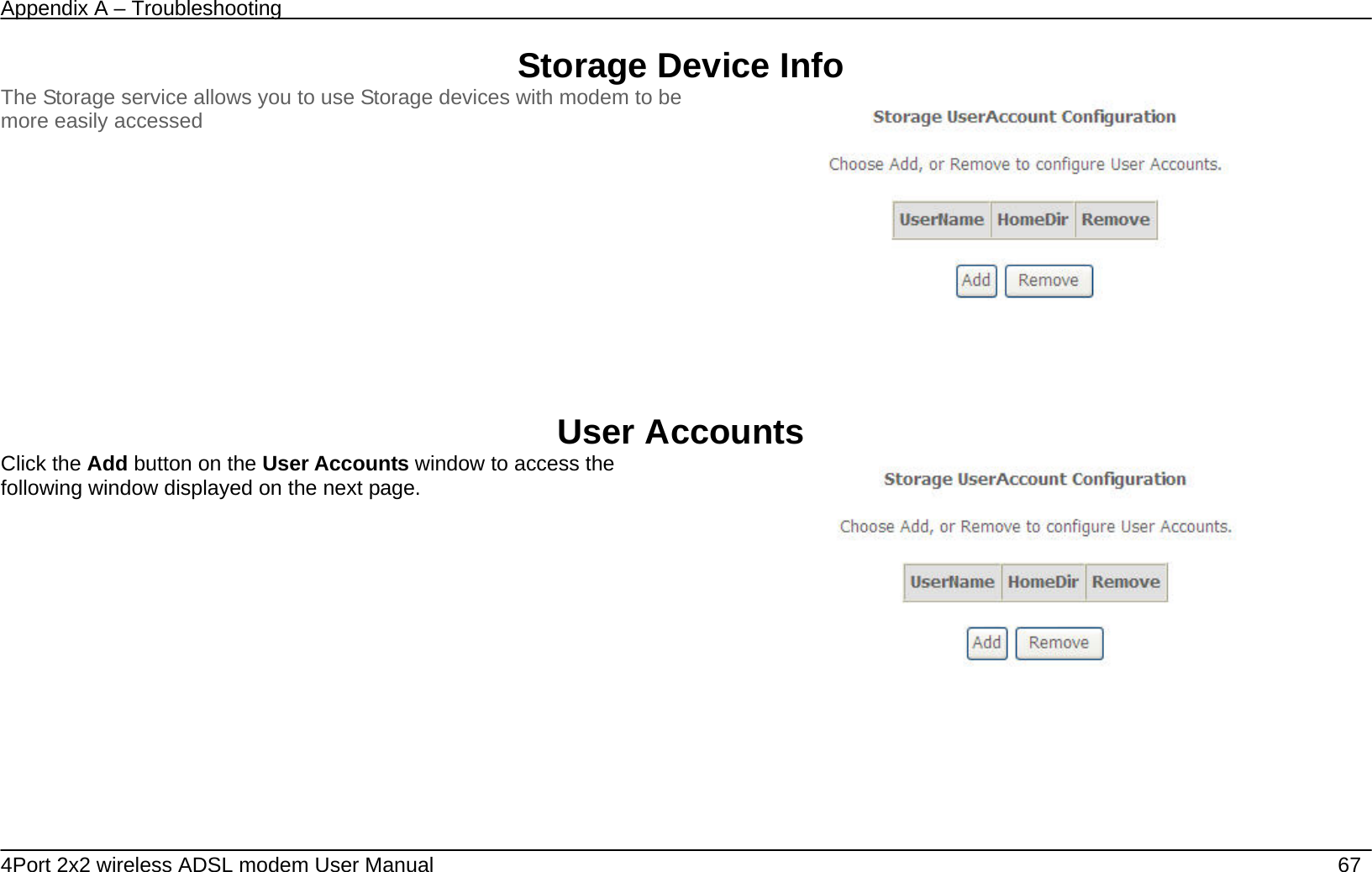
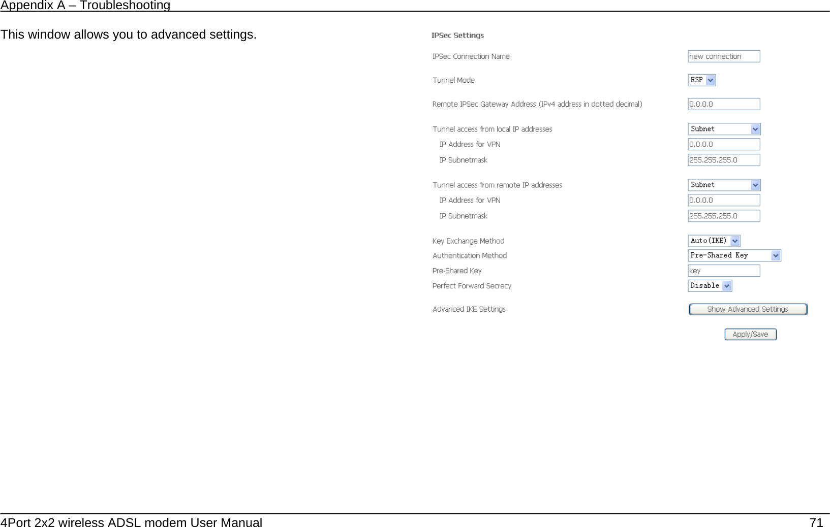
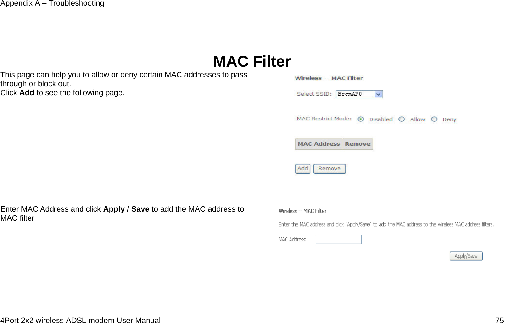
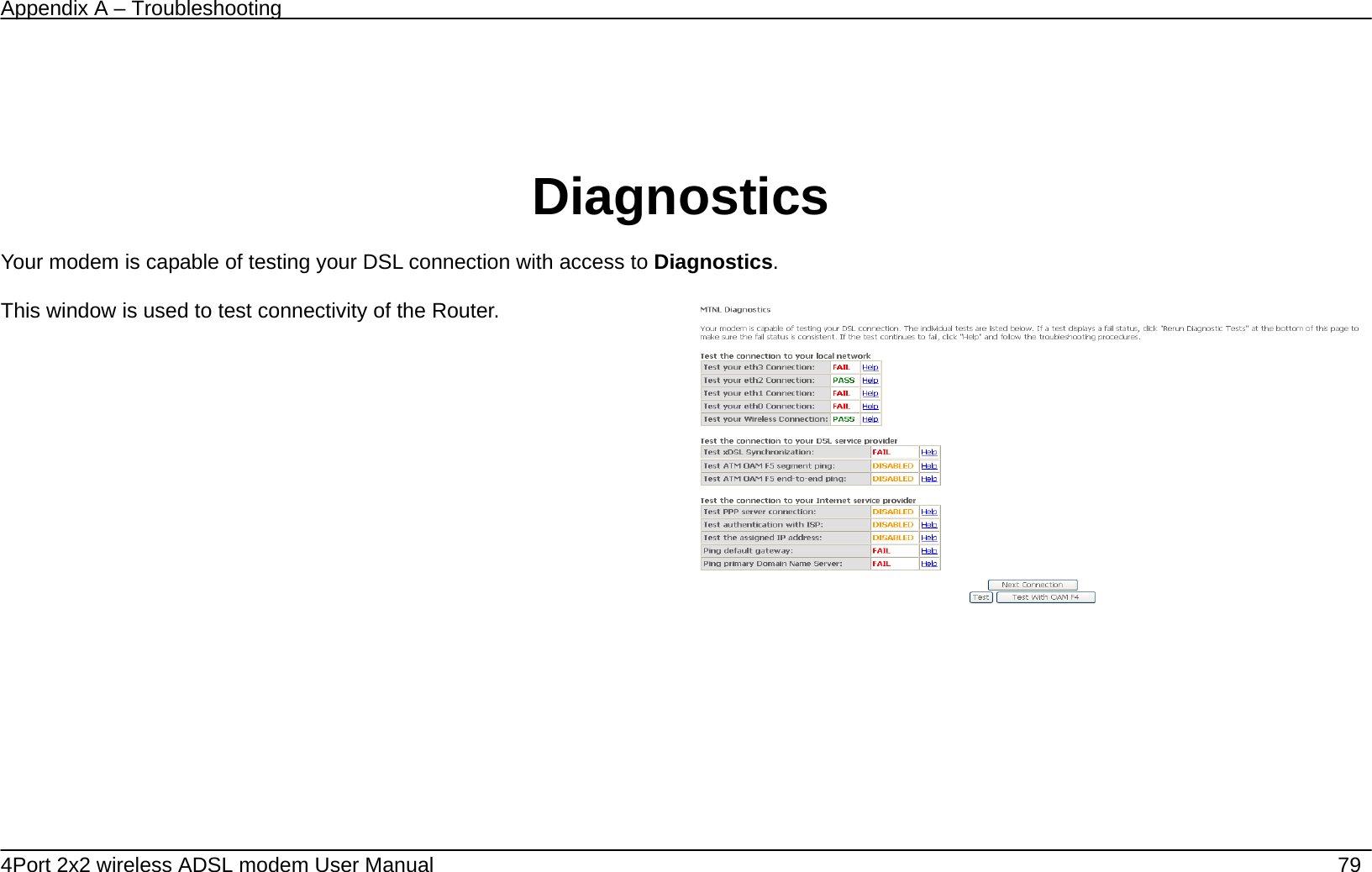
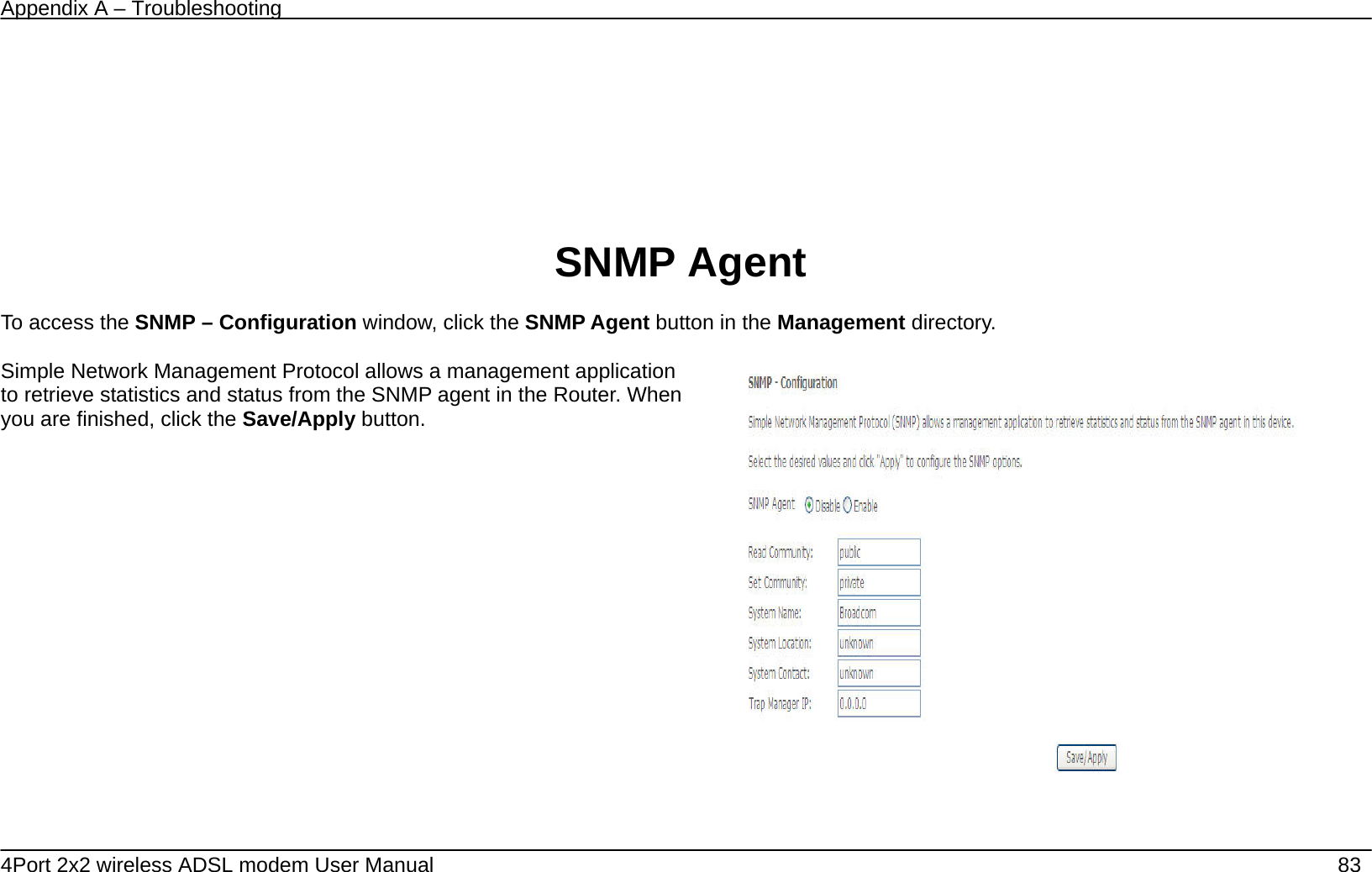
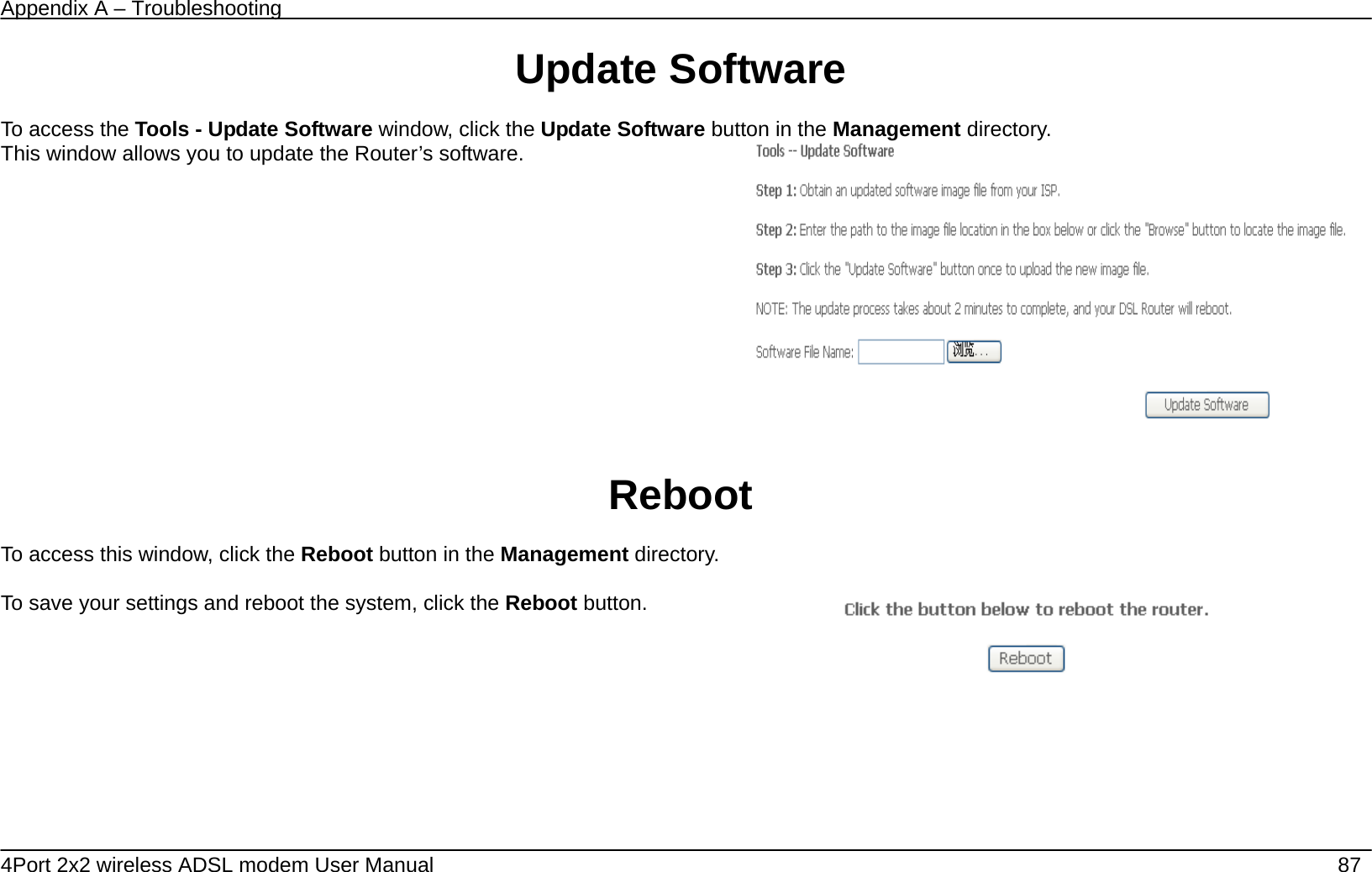
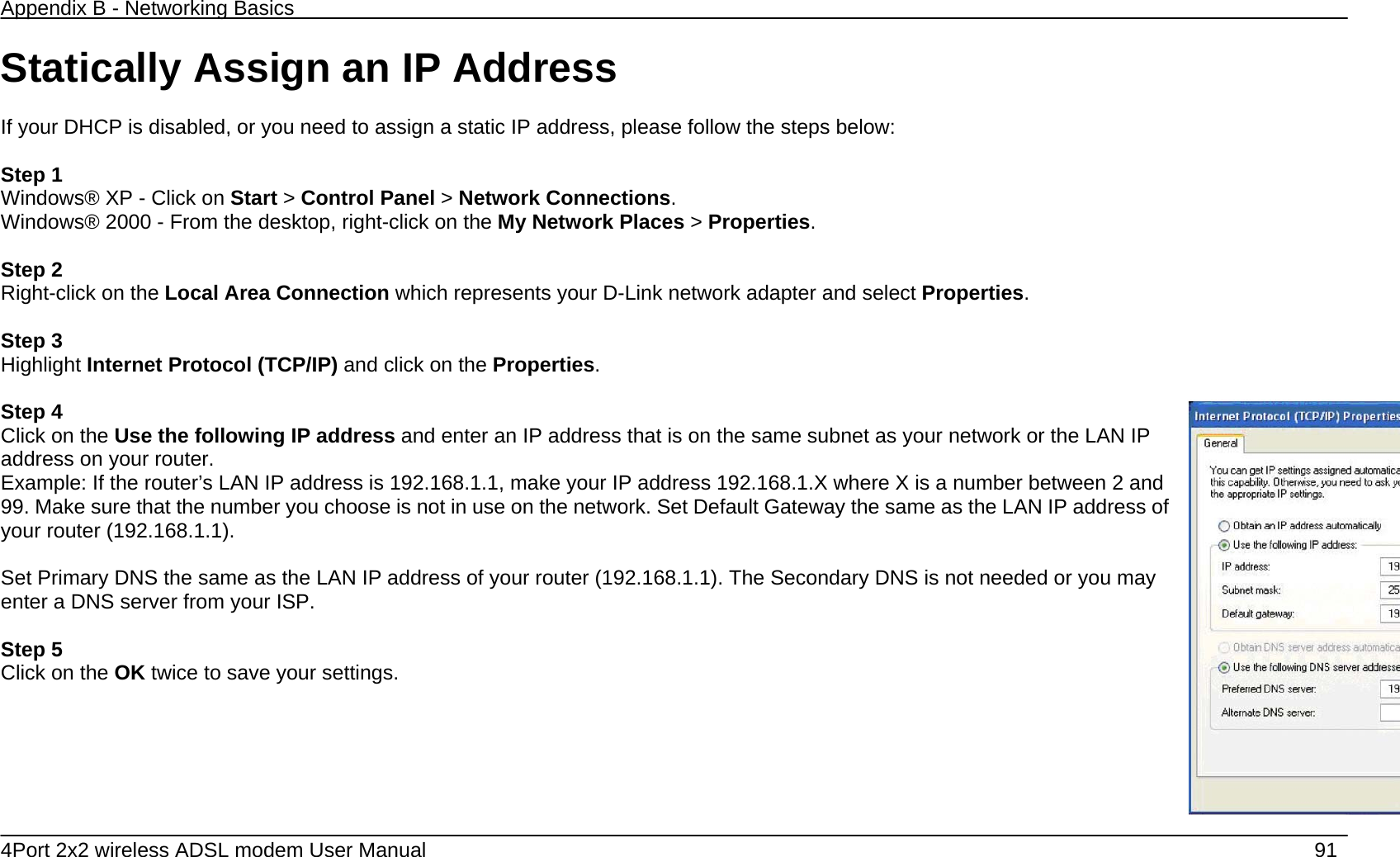
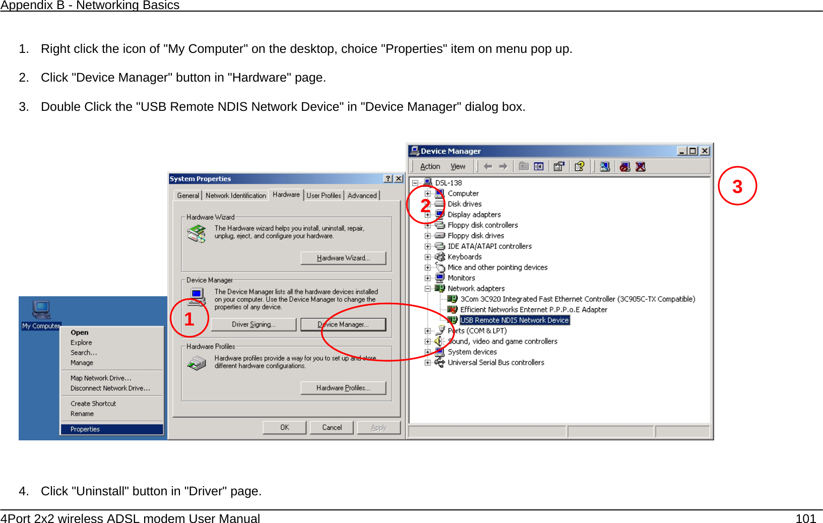
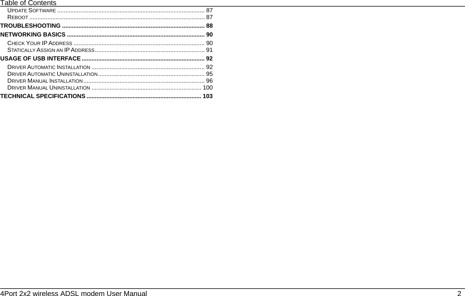
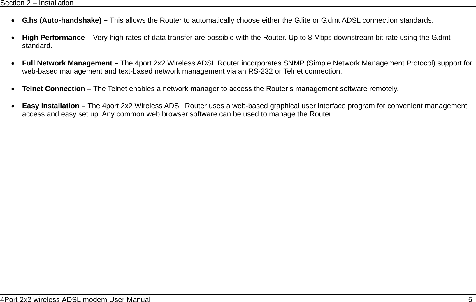
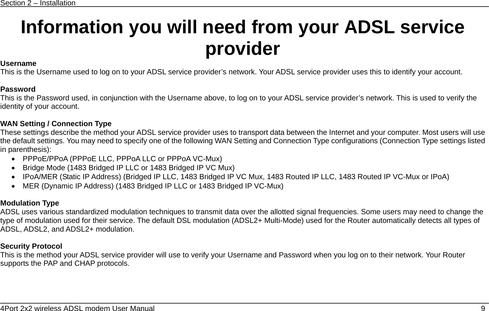
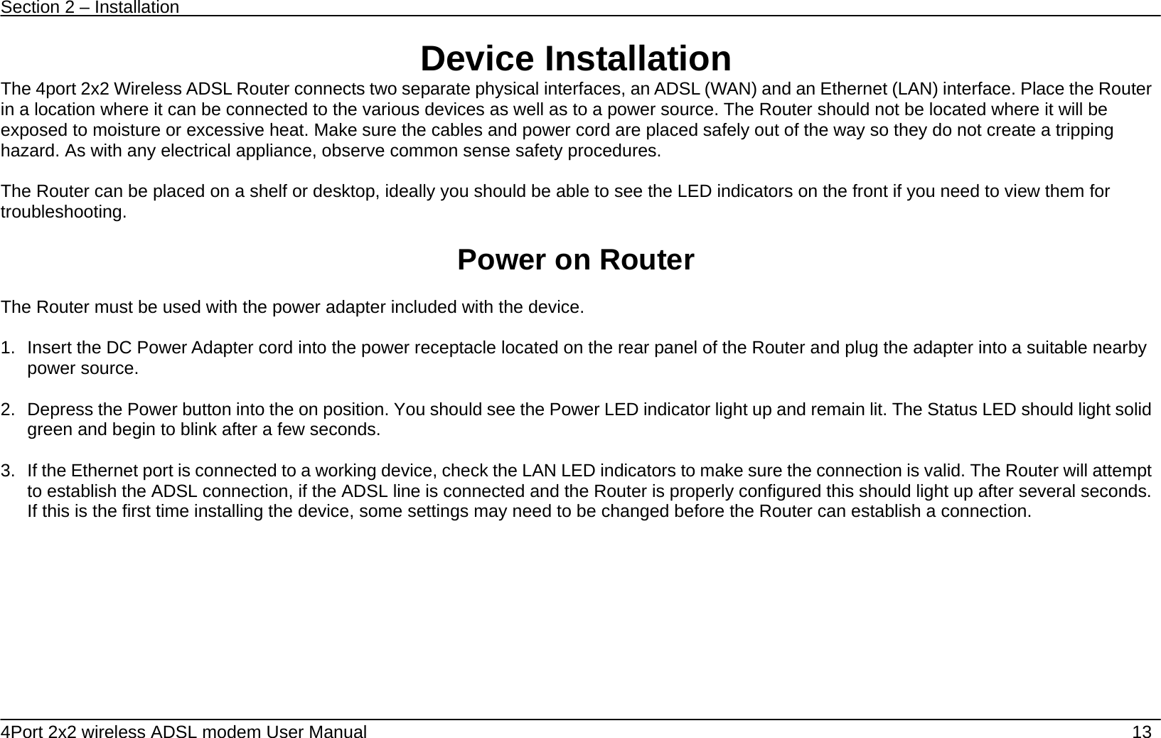
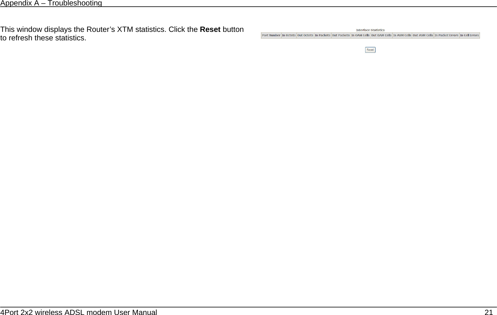
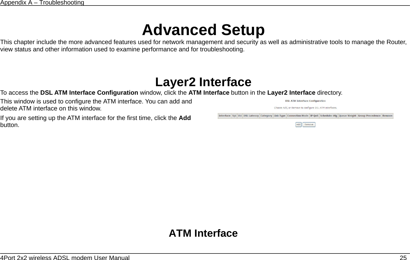
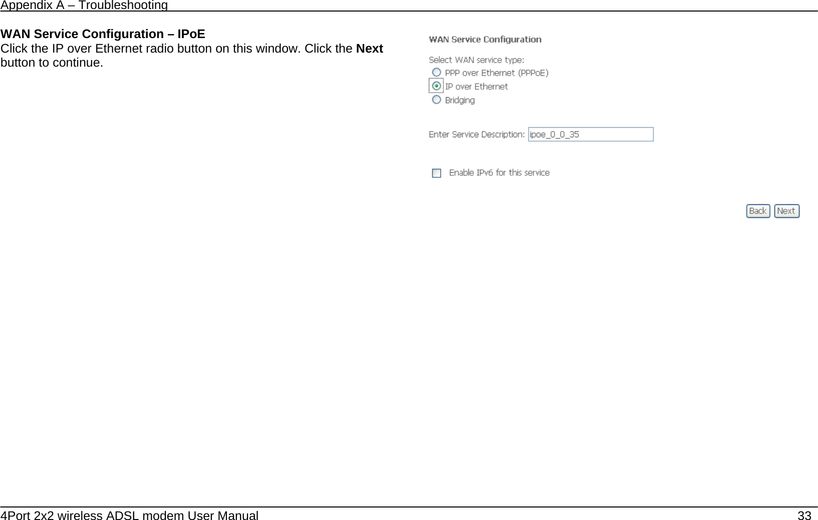
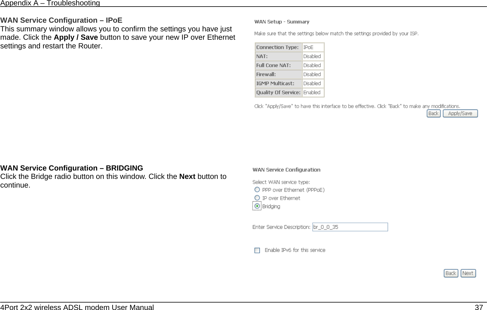
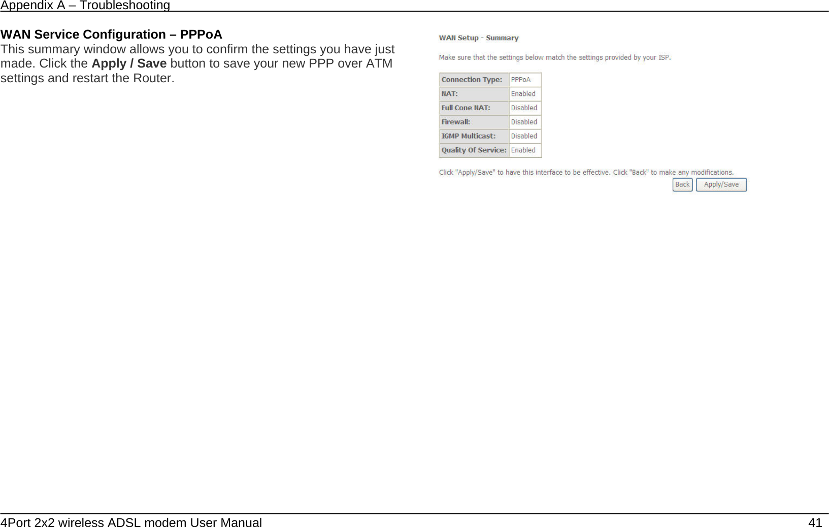
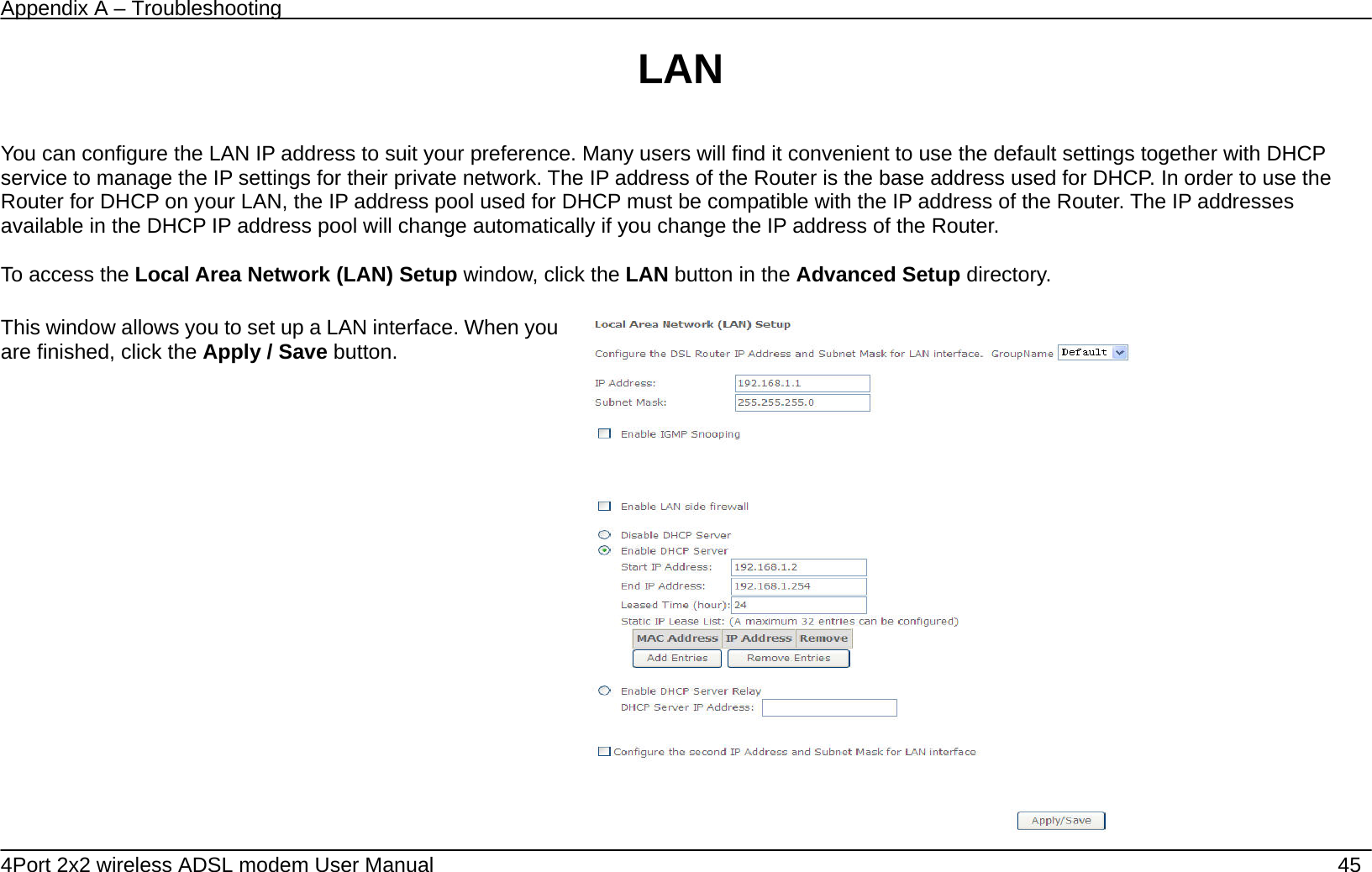
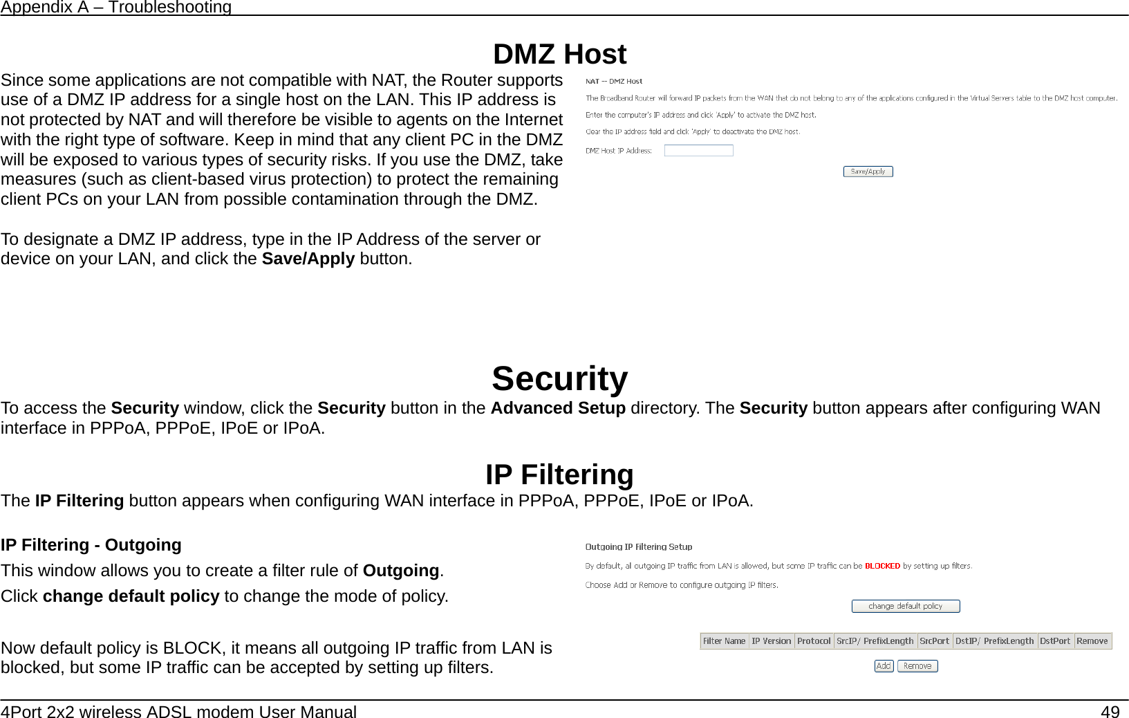
![Appendix A – Troubleshooting 4Port 2x2 wireless ADSL modem User Manual 52 Now default policy is BLOCK, it means all incoming IP traffic from WAN is blocked, but some IP traffic can be accepted by setting up filters. If you are setting up the incoming IP filtering, click the Add button. Enter the information in the section. Explanations of parameters are described below. Click the Apply / Save button to add the entry in the Active Inbound IP Filtering table. Filters Parameter Description Filter Name Enter a name for the new filter. IP Version Ipv4/Ipv6 Protocol Select the transport protocol (Any, TCP/UDP, TCP, UDP or ICMP) that will be used for the filter rule. Source IP address[/prefix length] Enter the start IP address which you are creating the filter rule. Source Port (port or port:port) The Source Port is the TCP/UDP port on either the LAN or WAN depending on if you are configuring an Outbound or Inbound Filter rule.](https://usermanual.wiki/DareGlobal-Technologies/A4001N/User-Guide-1971182-Page-52.png)
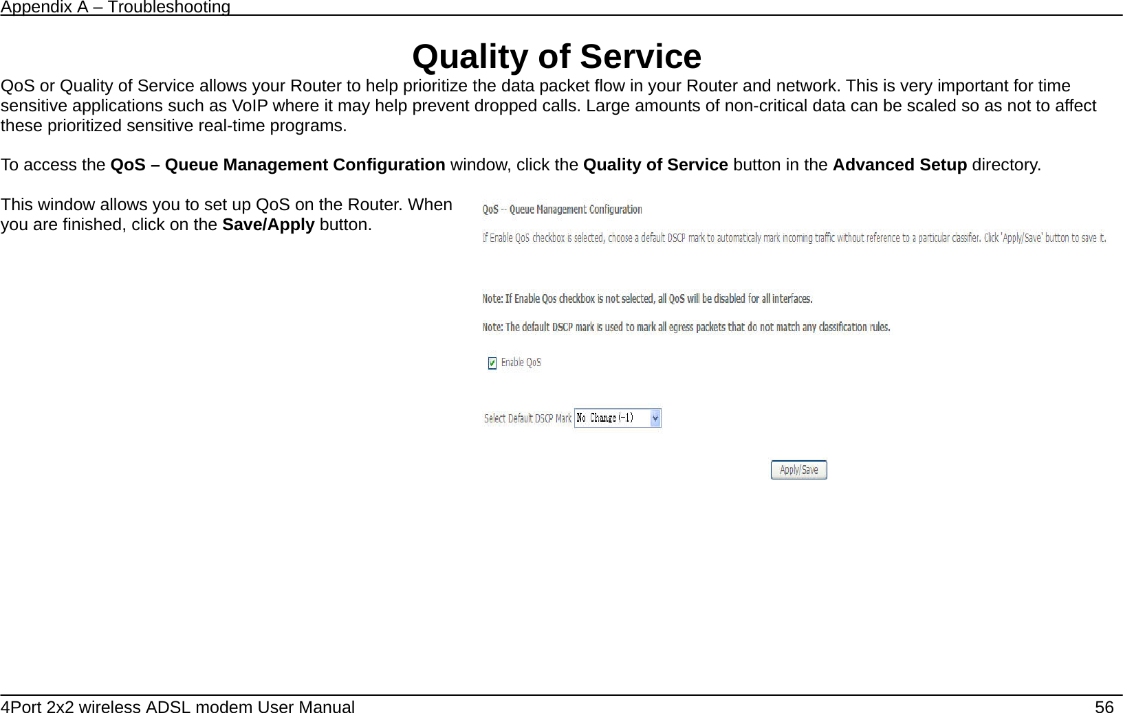
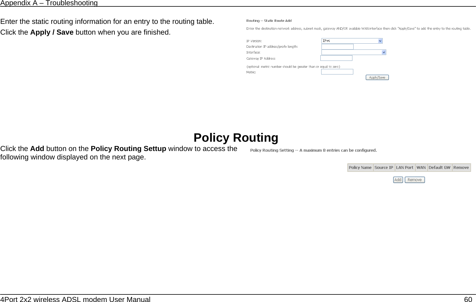
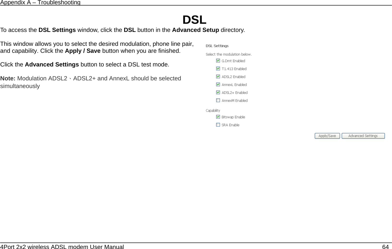
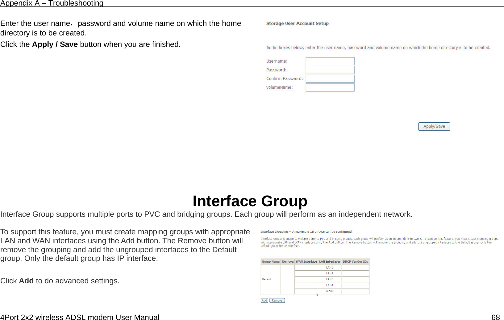
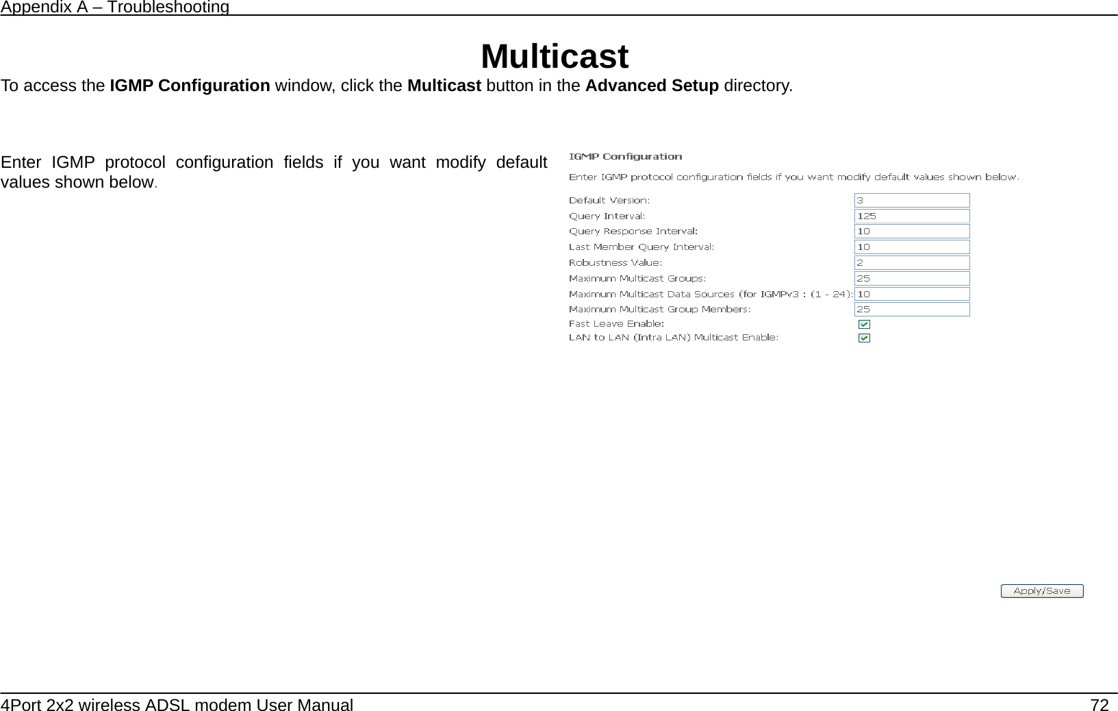
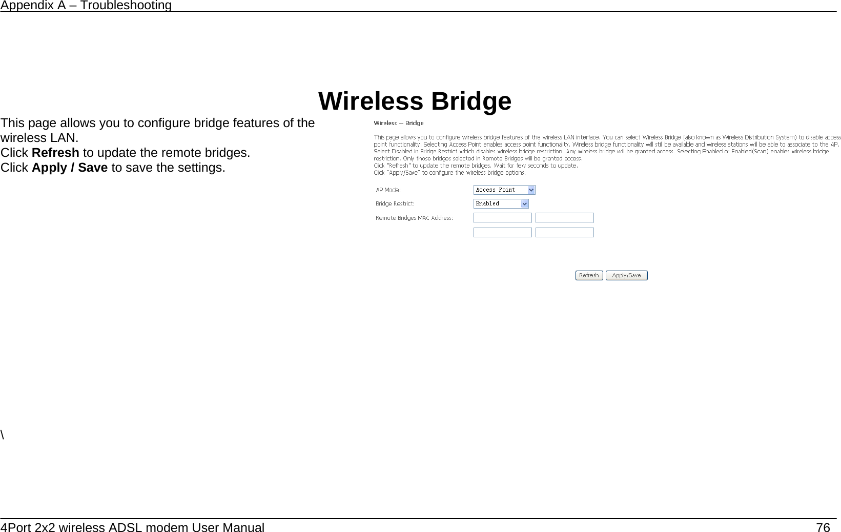
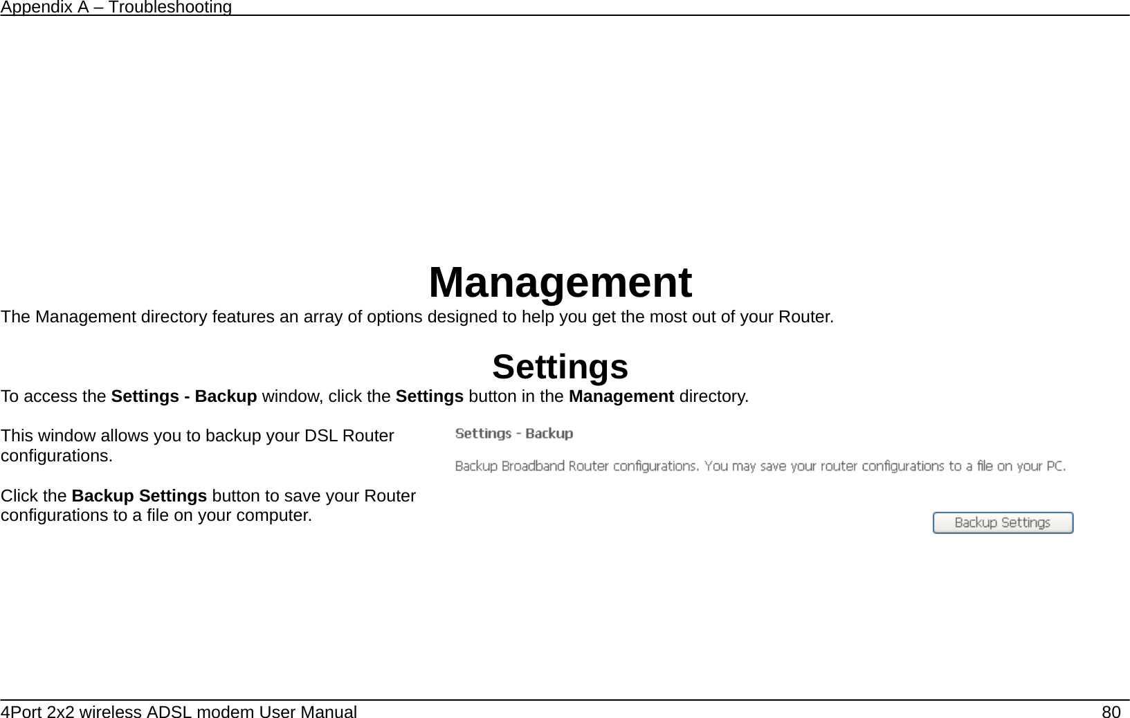
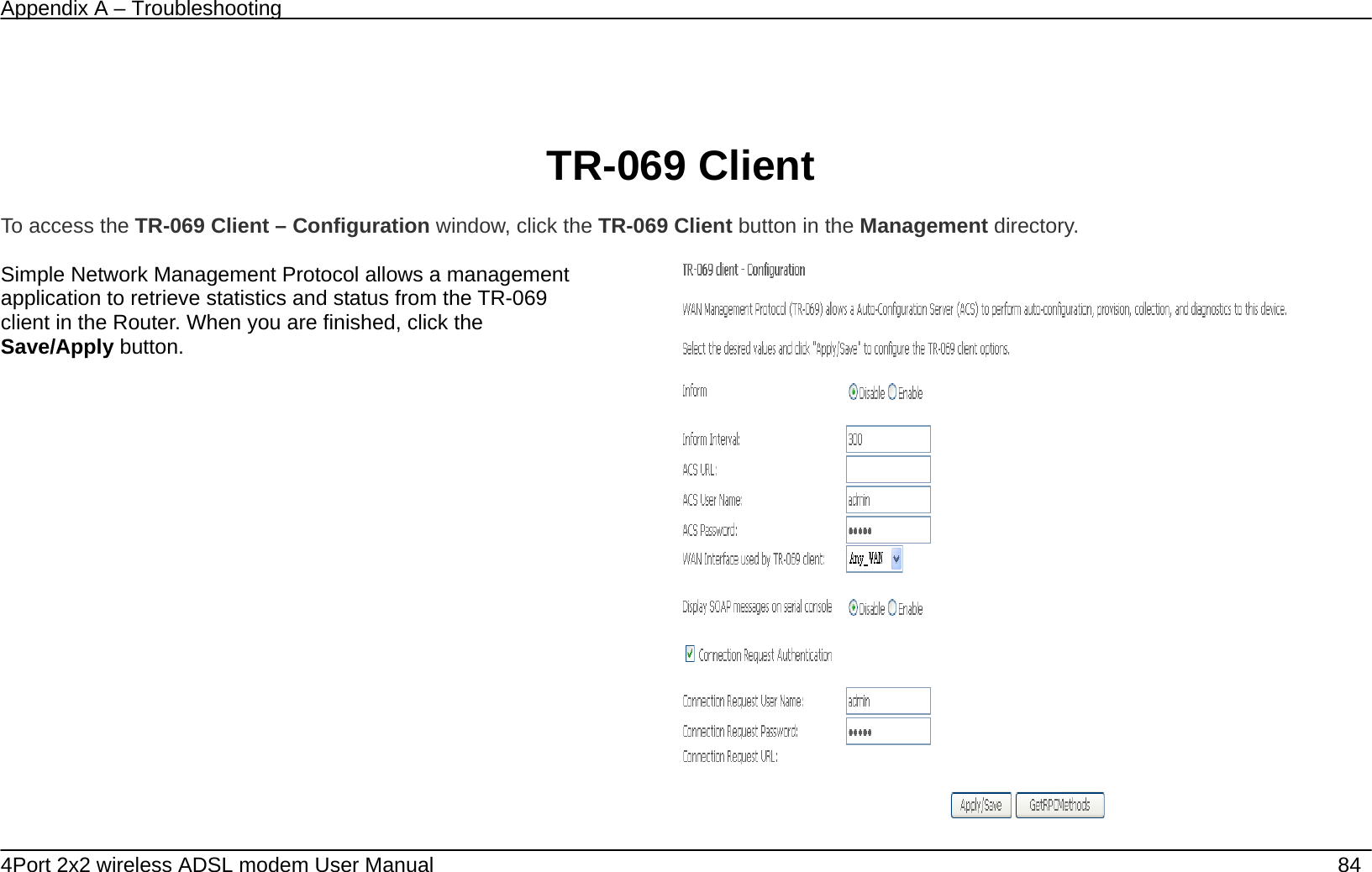
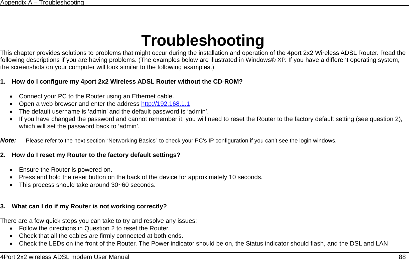
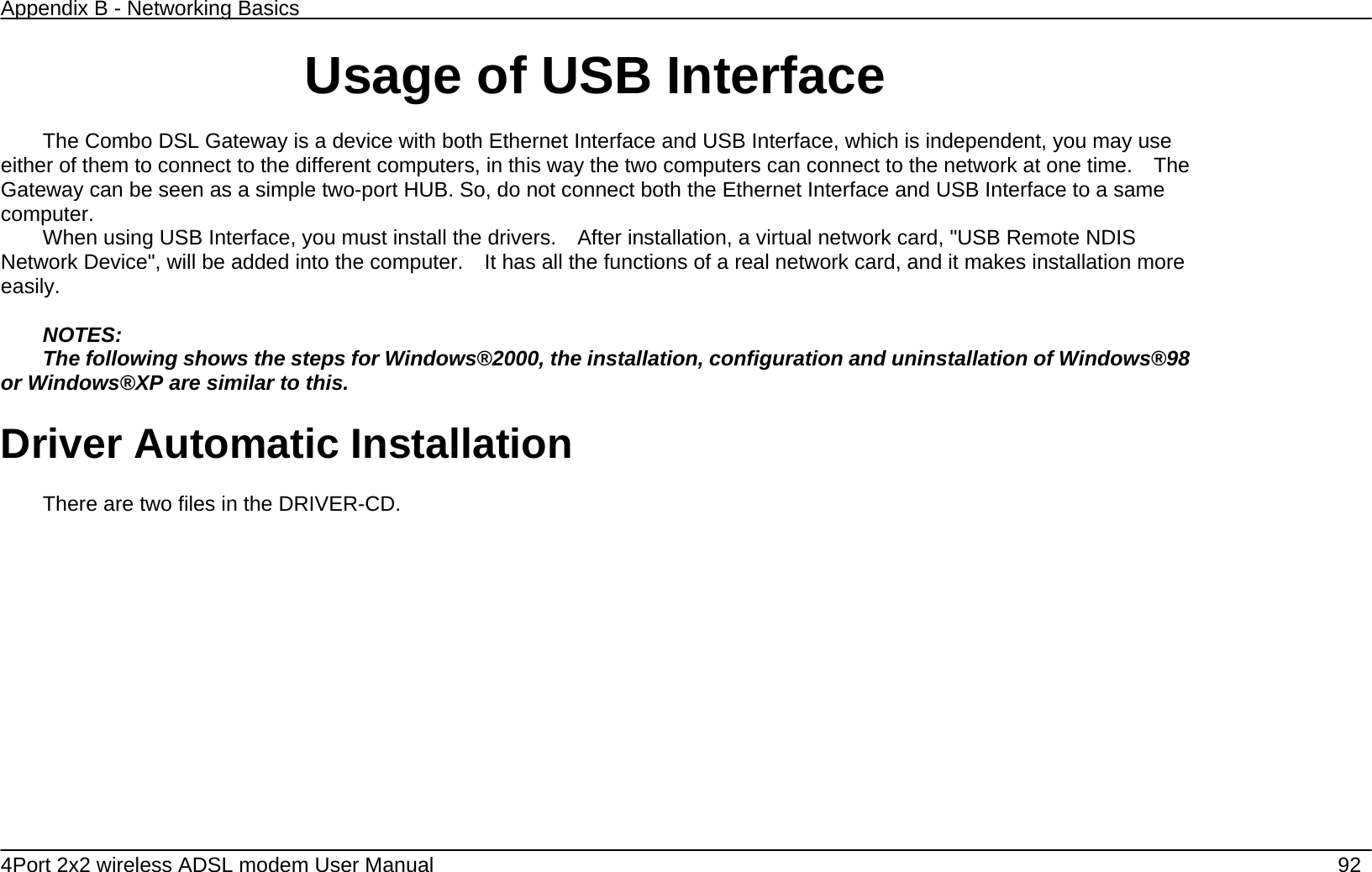
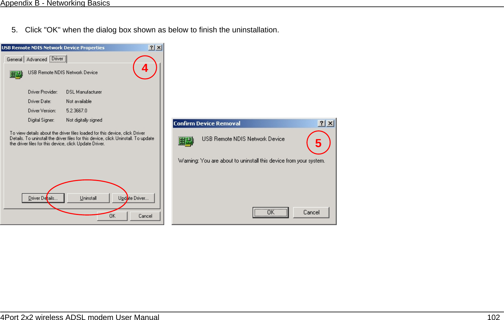
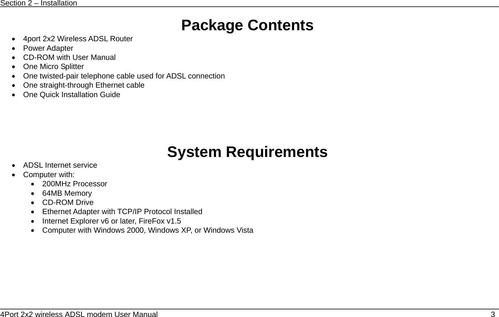
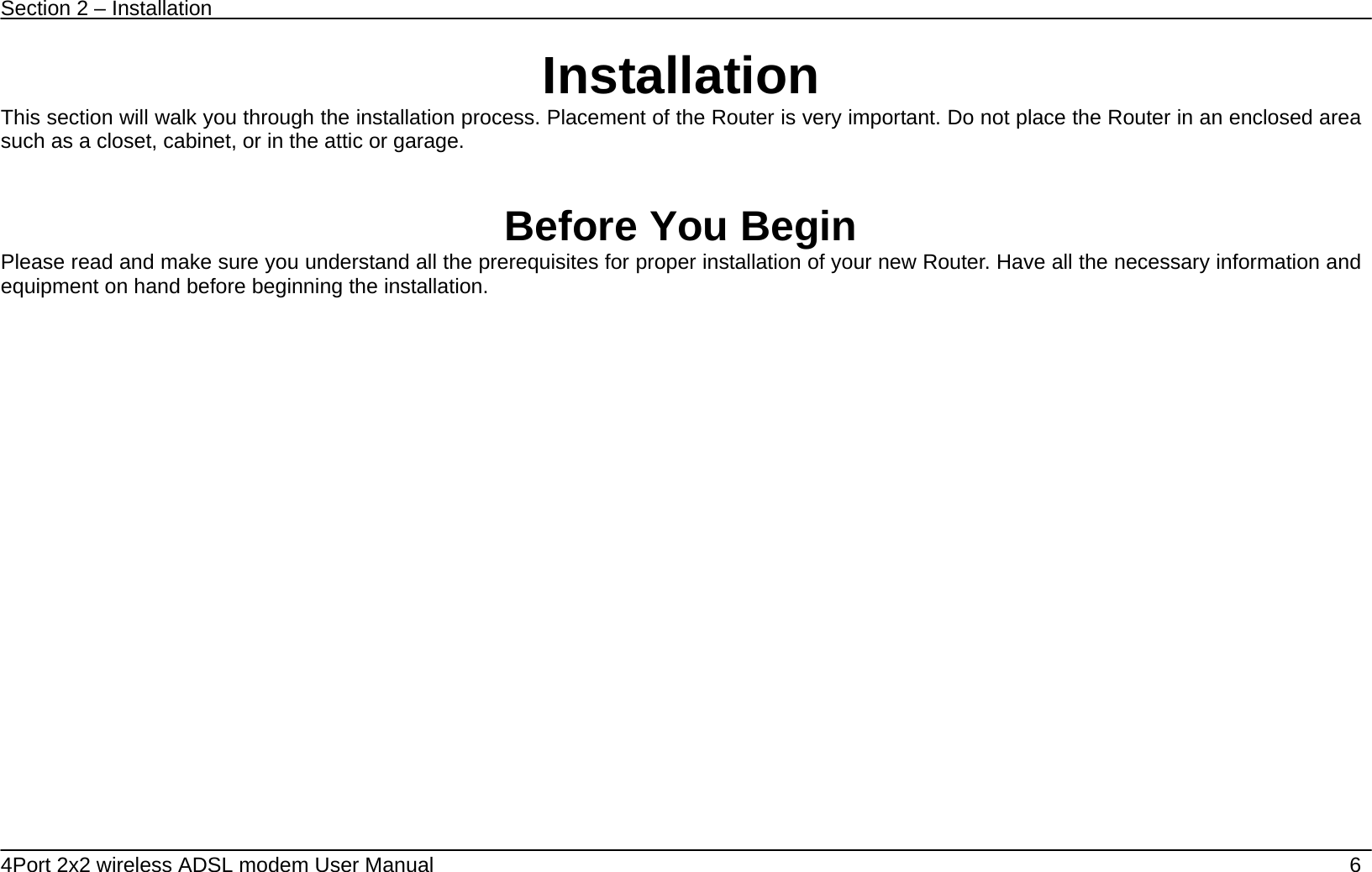
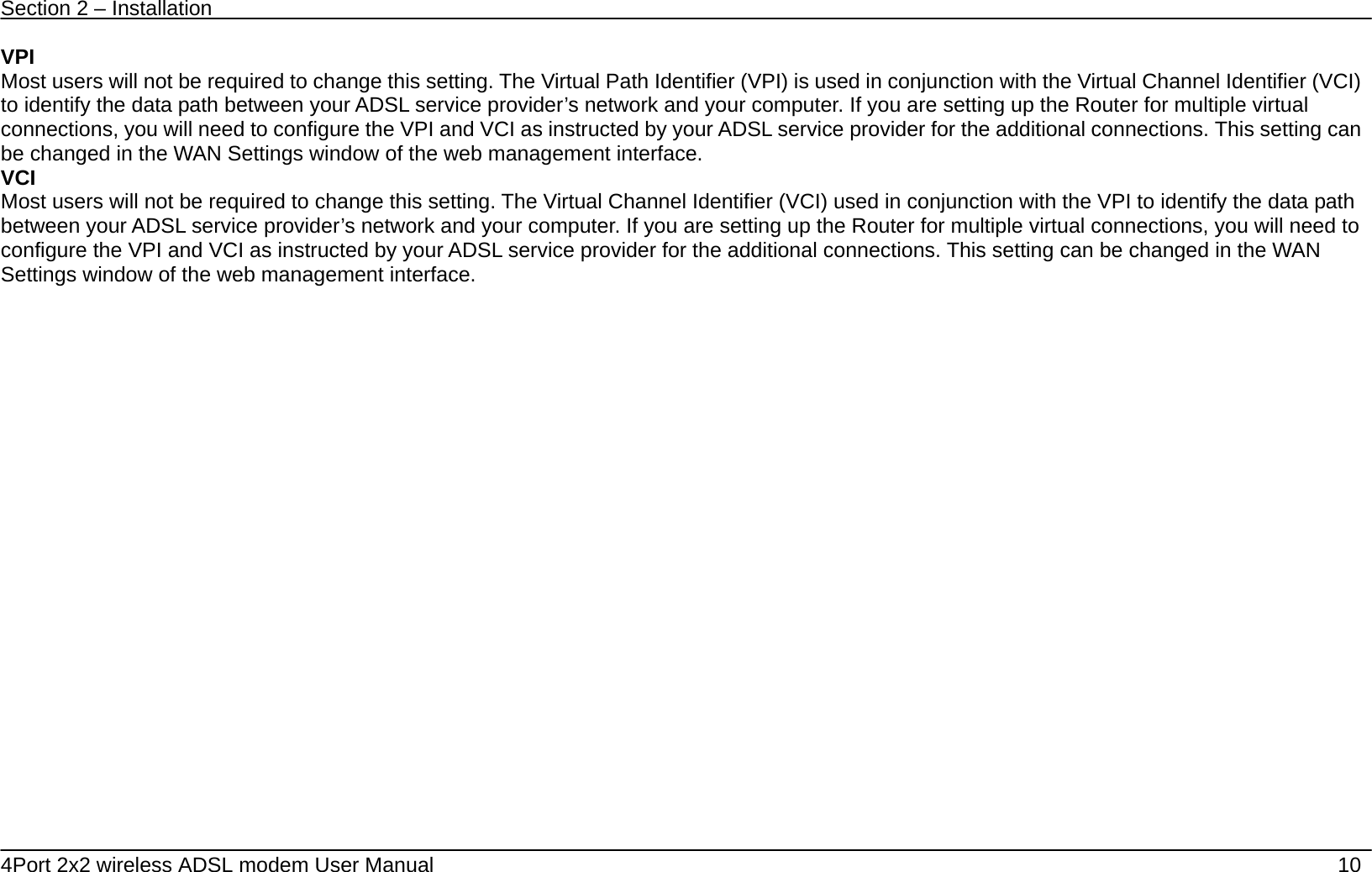
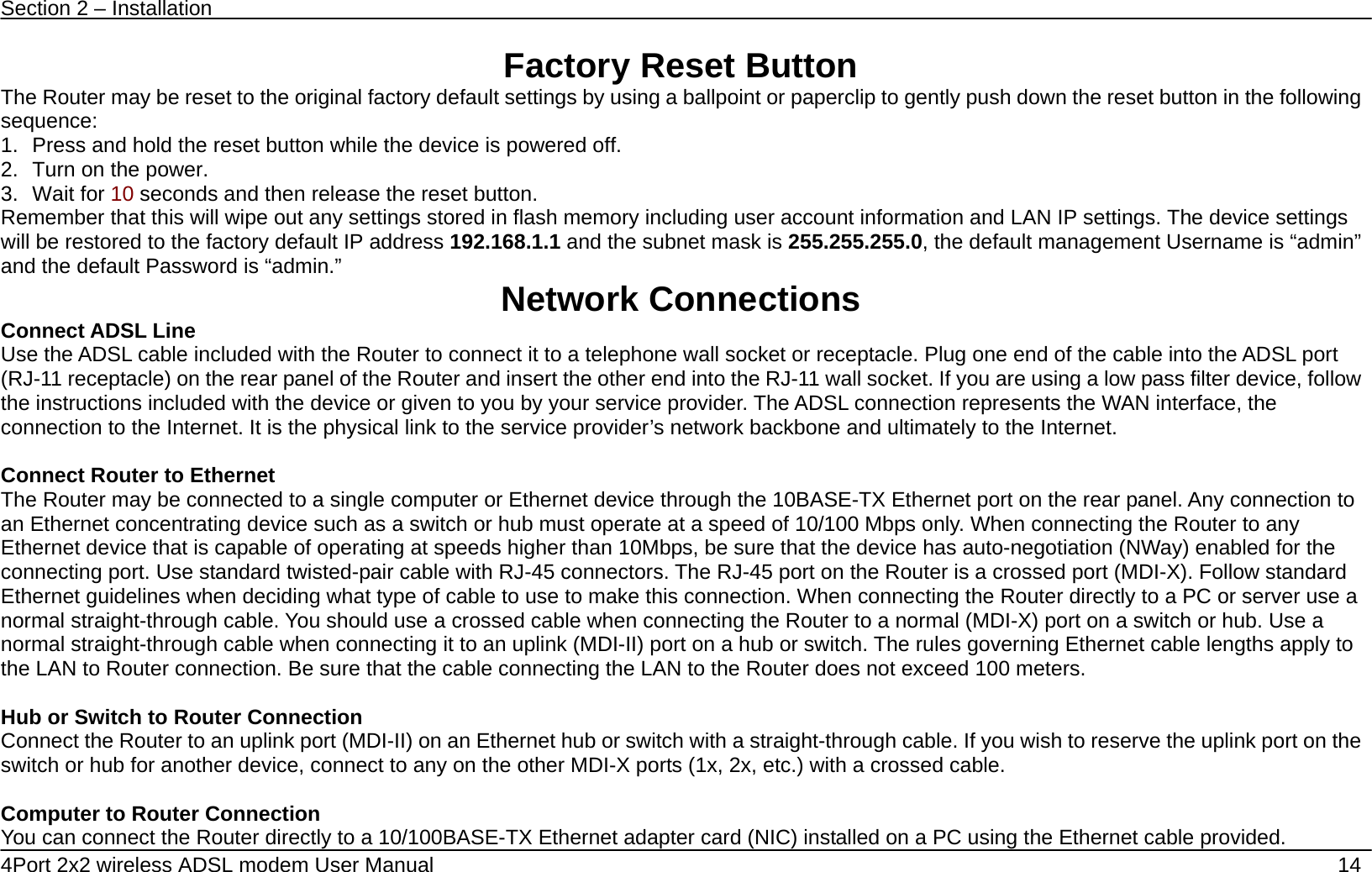
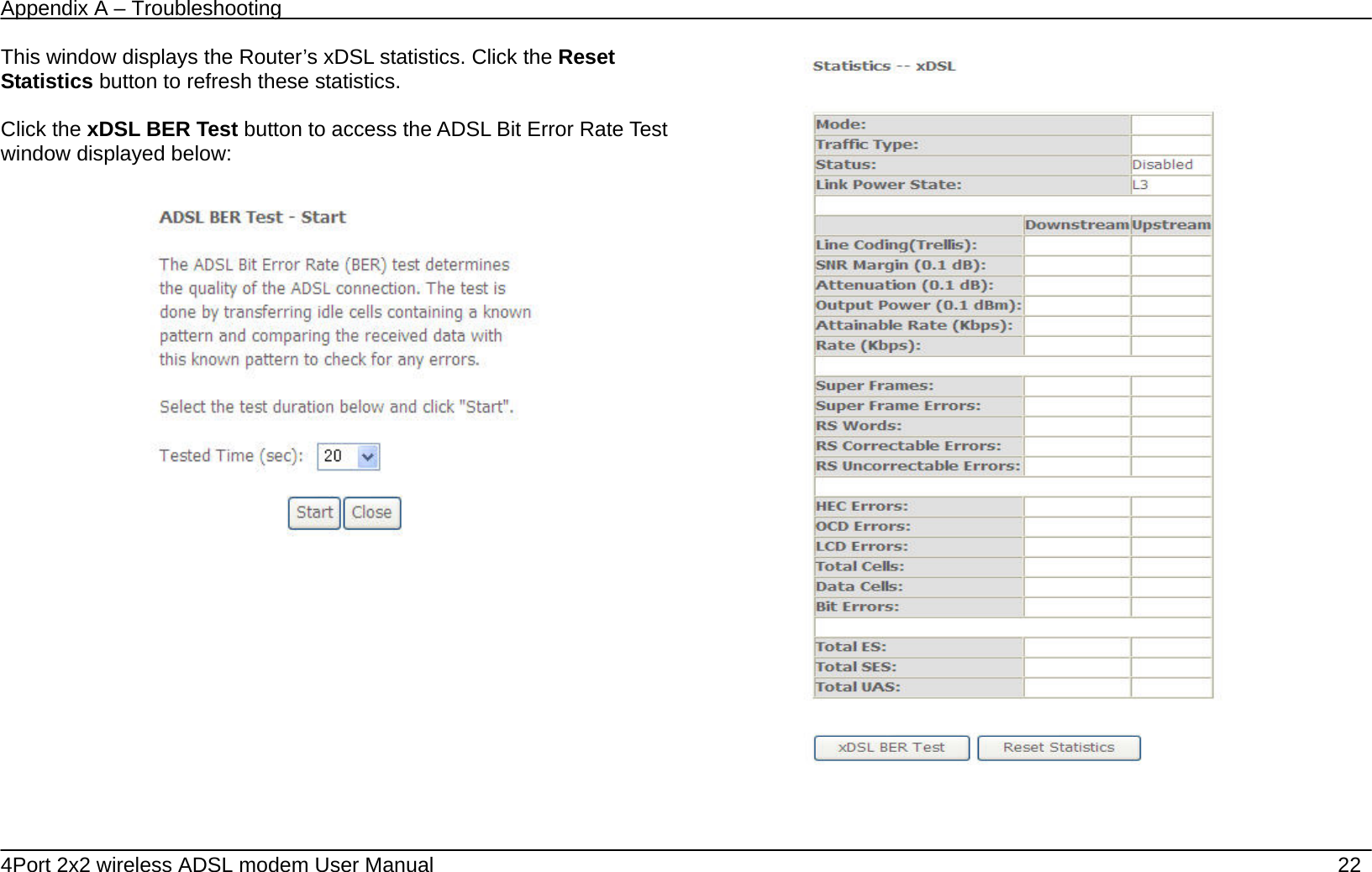
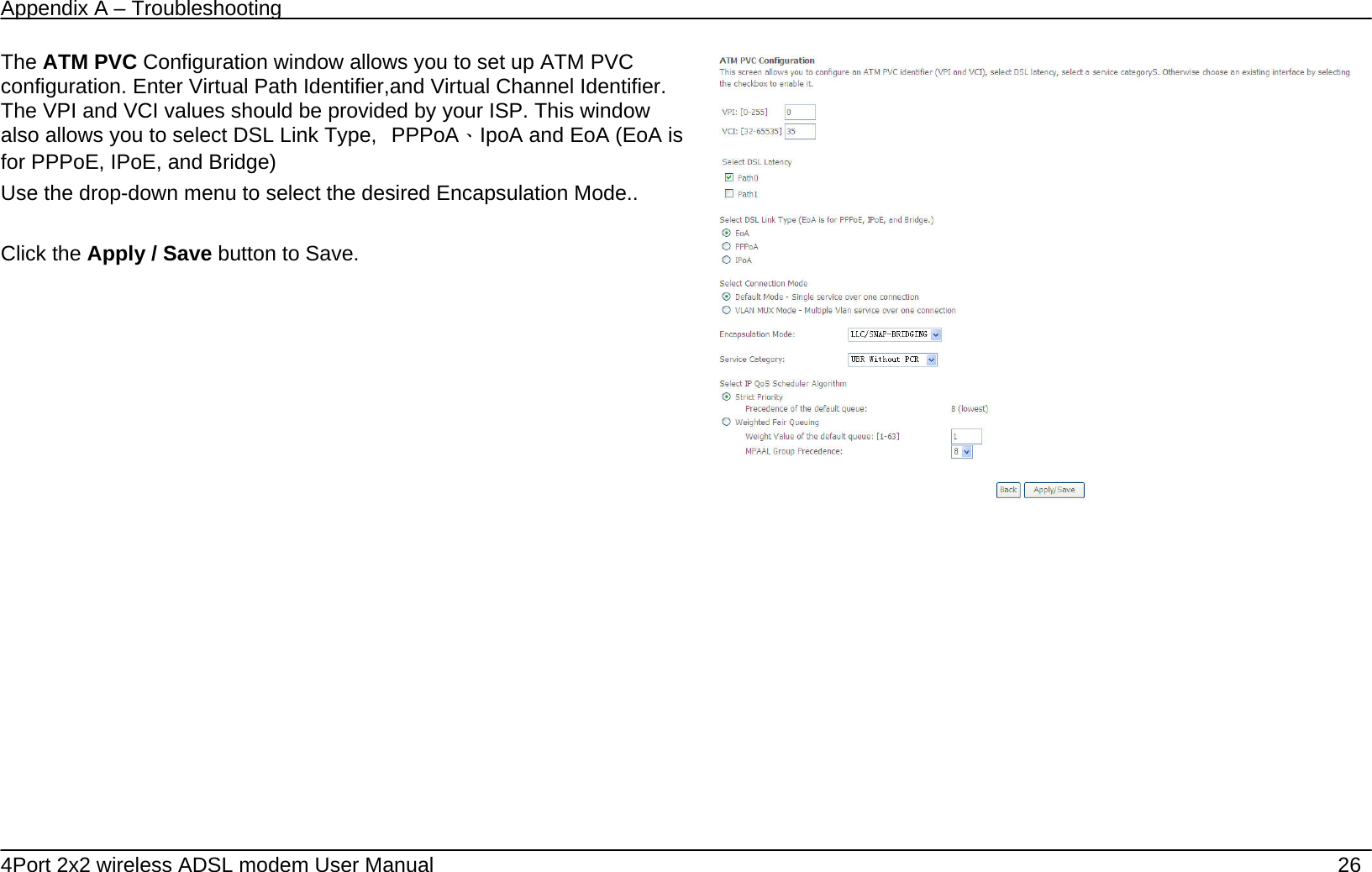
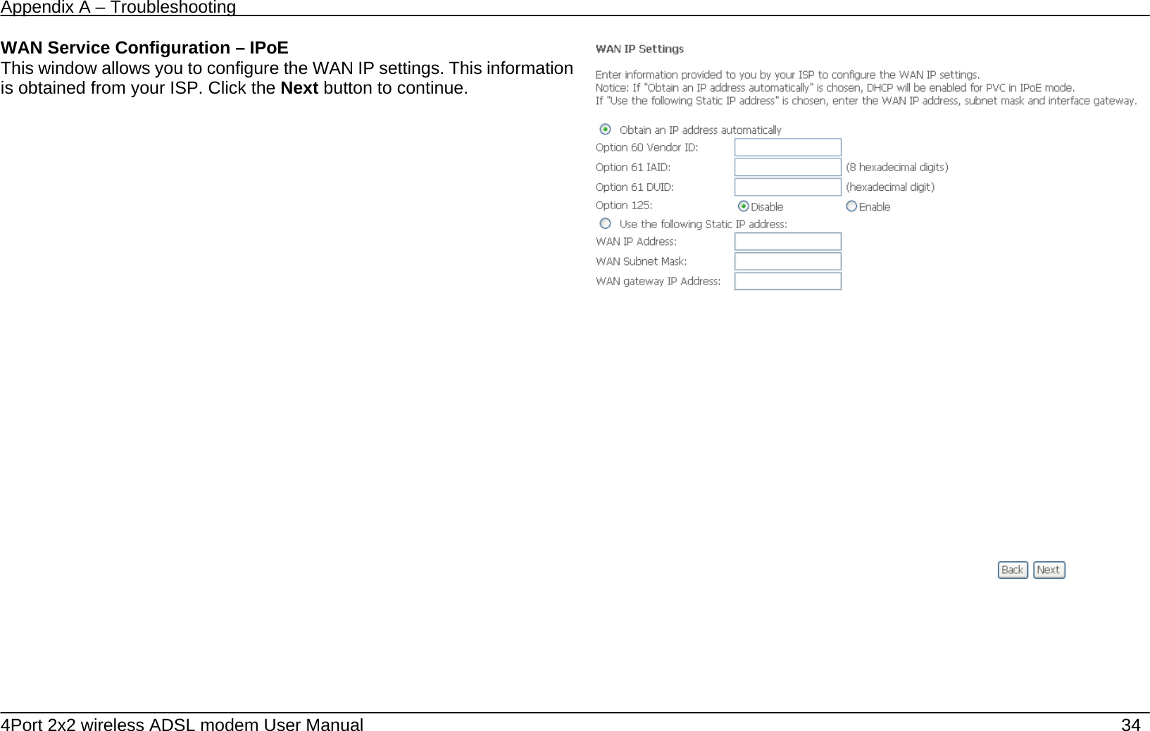
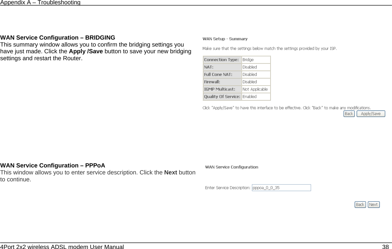
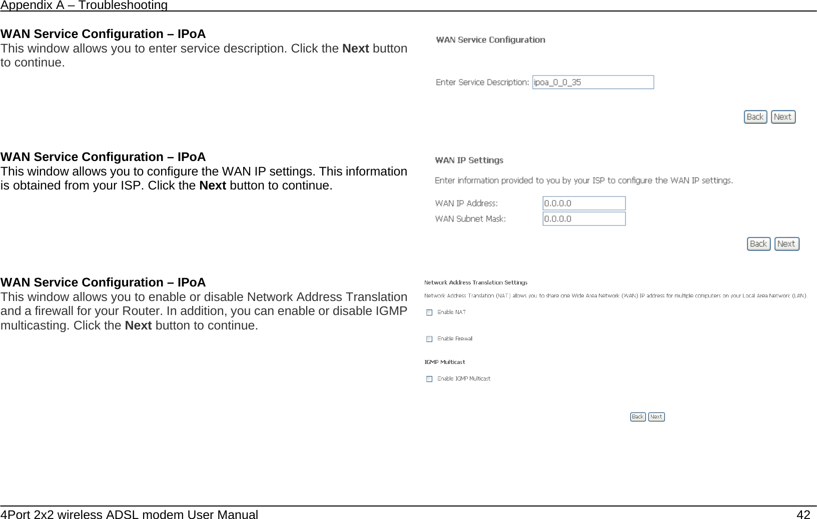
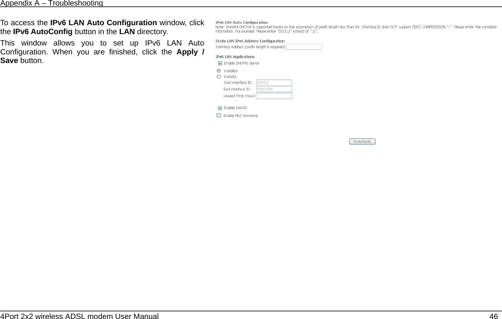
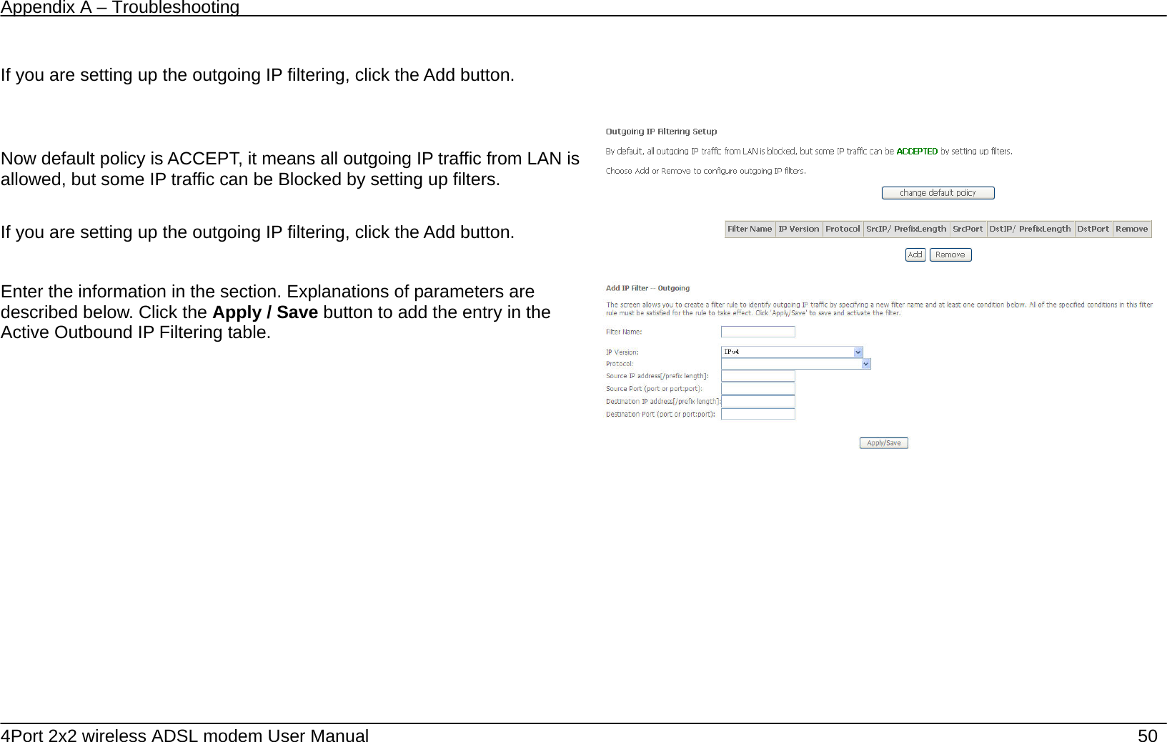
![Appendix A – Troubleshooting 4Port 2x2 wireless ADSL modem User Manual 53 Destination IP address[/prefix length] Enter the end IP address which you are creating the filter rule. Destination Port (port or port:port) The Destination Port is the TCP/UDP port on either the LAN or WAN depending on if you are configuring an Outbound or Inbound Filter rule. MAC Filtering TheMAC Filtering button appears when configuring WAN interface inBridge. MAC Filtering This window allows you to create a filter rule of MAC. Click change default policy to change the mode of policy. MAC Filtering is only effective on ATM PVCs configured in Bridge mode. FORWARDED means that all MAC layer frames will be FORWARDED except those matching with any of the specified rules in the following table. BLOCKED means that all MAC layer frames will be BLOCKED except those matching with any of the specified rules in the following table. MAC Filtering Policy For Each Interface: WARNING: Changing from one policy to another of an interface will cause all defined rules for that interface to be REMOVED AUTOMATICALLY! You will need to create new rules for the new policy. If you are setting up the MAC filtering, click the Add button. If you are setting up the MAC filtering, click the Add button.](https://usermanual.wiki/DareGlobal-Technologies/A4001N/User-Guide-1971182-Page-53.png)